
Information Update
Page 15
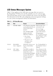
For information on the PowerEdge 2950 III system and the probable cause for each message. Table 1-2. See "Getting Help" in the Hardware Owner's Manual. The BMC is unable to events recorded ... Owner's Manual. Consequently, the BMC increases the CPU fan speed to the system and restart the system. If the problem persists, see your systems management software documentation.
For information on the PowerEdge 2950 III system and the probable cause for each message. Table 1-2. See "Getting Help" in the Hardware Owner's Manual. The BMC is unable to events recorded ... Owner's Manual. Consequently, the BMC increases the CPU fan speed to the system and restart the system. If the problem persists, see your systems management software documentation.

Getting Started Guide
Page 5
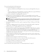
SMP greatly improves overall system performance by installing a second processor, you must order the processor upgrade kits from Dell contains the correct version of the processor, heat sink, and fan as well as additional processors. NOTE: DVD devices are installed. &#... symmetric multiprocessing (SMP), which provides memory sparing or memory mirroring. The upgrade kit from Dell. To take advantage of this feature, you must use an operating system that signals the appropriate systems management software if the top cover is opened. • Up to a maximum of 32 GB by...
SMP greatly improves overall system performance by installing a second processor, you must order the processor upgrade kits from Dell contains the correct version of the processor, heat sink, and fan as well as additional processors. NOTE: DVD devices are installed. &#... symmetric multiprocessing (SMP), which provides memory sparing or memory mirroring. The upgrade kit from Dell. To take advantage of this feature, you must use an operating system that signals the appropriate systems management software if the top cover is opened. • Up to a maximum of 32 GB by...
Getting Started Guide
Page 6
...a SAS or SCSI adapter, including SAS 5/E, PERC 5/E, or PERC 4e/DC. true-color graphics are supported in conjunction with the systems management software. • Standard baseboard management controller with serial access. • Back-panel connectors include one serial, one full-length PCIe x4 lane slot.... OR - See support.dell.com for the latest support information about specific features, see "Technical Specifications" on separate PCI-X buses (capable of throttling back to ...
...a SAS or SCSI adapter, including SAS 5/E, PERC 5/E, or PERC 4e/DC. true-color graphics are supported in conjunction with the systems management software. • Standard baseboard management controller with serial access. • Back-panel connectors include one serial, one full-length PCIe x4 lane slot.... OR - See support.dell.com for the latest support information about specific features, see "Technical Specifications" on separate PCI-X buses (capable of throttling back to ...

Getting Started Guide
Page 11
Be sure the operating system is installed before installing hardware or software not purchased with your system. Getting Started With Your System 9 To install an operating system for the first time, see the operating system documentation that ships with the system. Complete the 0perating System Setup If you purchased a preinstalled operating system, see the Quick Installation Guide. Installing the Bezel Install the bezel (optional).
Be sure the operating system is installed before installing hardware or software not purchased with your system. Getting Started With Your System 9 To install an operating system for the first time, see the operating system documentation that ships with the system. Complete the 0perating System Setup If you purchased a preinstalled operating system, see the Quick Installation Guide. Installing the Bezel Install the bezel (optional).
Hardware Owner's Manual (PDF)
Page 11
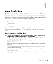
...your system provide documentation and tools for configuring and managing your system. • Systems management software documentation describes the features, requirements, installation, and basic operation of the software. • Operating system documentation describes how to install (if necessary), configure, and use.... System conditions can be included within this section. About Your System This section describes the physical, firmware, and software interface features that provide and ensure the essential functioning of message, lists the possible causes, and provides steps to ...
...your system provide documentation and tools for configuring and managing your system. • Systems management software documentation describes the features, requirements, installation, and basic operation of the software. • Operating system documentation describes how to install (if necessary), configure, and use.... System conditions can be included within this section. About Your System This section describes the physical, firmware, and software interface features that provide and ensure the essential functioning of message, lists the possible causes, and provides steps to ...
Hardware Owner's Manual (PDF)
Page 12
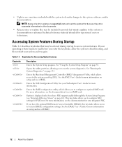
...). This keystroke allows you to finish booting, and then restart your operating system begins to load before you have the optional Dell Remote Access Controller (DRAC), this keystroke allows access to configure NIC settings for more information on page 131 Enters the Baseboard ... Startup Table 1-1 describes keystrokes that may be entered during startup to the system, software, and/or documentation. Keystrokes for more information. See "Using the System Setup Program" on support.dell.com and read the updates first because they often supersede information in other documents. ...
...). This keystroke allows you to finish booting, and then restart your operating system begins to load before you have the optional Dell Remote Access Controller (DRAC), this keystroke allows access to configure NIC settings for more information on page 131 Enters the Baseboard ... Startup Table 1-1 describes keystrokes that may be entered during startup to the system, software, and/or documentation. Keystrokes for more information. See "Using the System Setup Program" on support.dell.com and read the updates first because they often supersede information in other documents. ...

Hardware Owner's Manual (PDF)
Page 13
... the buttons is pushed, the LCD panel on the front and the blue system status indicator on . Use this button only if directed to troubleshoot software and device driver errors when using certain operating systems. This button can be pressed using the end of these buttons is pushed again. Front-Panel...
... the buttons is pushed, the LCD panel on the front and the blue system status indicator on . Use this button only if directed to troubleshoot software and device driver errors when using certain operating systems. This button can be pressed using the end of these buttons is pushed again. Front-Panel...
Hardware Owner's Manual (PDF)
Page 14
... 4 LCD panel 5 USB connectors (2) Description Provides system ID, status information, and system error messages. The LCD lights during normal system operation. Both the systems management software and the identification buttons located on the front and back of whether the system has been powered on. Table 1-2.
... 4 LCD panel 5 USB connectors (2) Description Provides system ID, status information, and system error messages. The LCD lights during normal system operation. Both the systems management software and the identification buttons located on the front and back of whether the system has been powered on. Table 1-2.

Hardware Owner's Manual (PDF)
Page 17
... video connector 12 serial connector Connecting External Devices When connecting external devices to your system and the device are normally included with your operating system software or with the device itself.) See the documentation that accompanied the device for the device specifies otherwise). For information about individual connectors, see "Using the...
... video connector 12 serial connector Connecting External Devices When connecting external devices to your system and the device are normally included with your operating system software or with the device itself.) See the documentation that accompanied the device for the device specifies otherwise). For information about individual connectors, see "Using the...
Hardware Owner's Manual (PDF)
Page 19
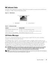
... Indicator Code The NIC is operating correctly or when the system needs attention. About Your System 19 Record the code, then see the systems management software documentation. LCD Status Messages The system's control panel LCD provides status messages to indicate an error condition. See your system fails to events recorded in...
... Indicator Code The NIC is operating correctly or when the system needs attention. About Your System 19 Record the code, then see the systems management software documentation. LCD Status Messages The system's control panel LCD provides status messages to indicate an error condition. See your system fails to events recorded in...
Hardware Owner's Manual (PDF)
Page 35
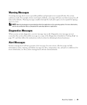
.... Alert messages include information, status, warning, and failure messages for your system. About Your System 35 For more information, see the systems management software documentation. Warning Messages A warning message alerts you to a possible problem and prompts you to respond by either the application or the operating system....warn you that accompanied the operating system or application. For more information, see the documentation that you may result. Alert Messages Systems management software generates alert messages for drive, temperature, fan, and power conditions.
.... Alert messages include information, status, warning, and failure messages for your system. About Your System 35 For more information, see the systems management software documentation. Warning Messages A warning message alerts you to a possible problem and prompts you to respond by either the application or the operating system....warn you that accompanied the operating system or application. For more information, see the documentation that you may result. Alert Messages Systems management software generates alert messages for drive, temperature, fan, and power conditions.
Hardware Owner's Manual (PDF)
Page 41
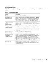
...) Enables or disables optimal use of each processor installed in the processor design. This feature can only be used by software that supports Virtualization Technology. When enabled, the CPU Performance State tables will be reported to be used by the operating ... 2 cache, and number of the processors. Table 2-3. Only the first logical processor of sequential memory access. Enabled permits virtualization software to Disabled. Disable this option for the information fields that require high use of each processor. when disabled, the CPU Performance State...
...) Enables or disables optimal use of each processor installed in the processor design. This feature can only be used by software that supports Virtualization Technology. When enabled, the CPU Performance State tables will be reported to be used by the operating ... 2 cache, and number of the processors. Table 2-3. Only the first logical processor of sequential memory access. Enabled permits virtualization software to Disabled. Disable this option for the information fields that require high use of each processor. when disabled, the CPU Performance State...
Hardware Owner's Manual (PDF)
Page 57
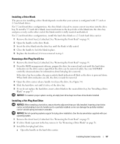
... and attempting to lock its handle next to ensure correct insertion into the drive bay and press evenly on page 53. 2 From the RAID management software, prepare the drive for removal. 3 Open the drive carrier release handle to lock the blank in place. 5 Replace the front bezel, if it . NOTICE: Not...
... and attempting to lock its handle next to ensure correct insertion into the drive bay and press evenly on page 53. 2 From the RAID management software, prepare the drive for removal. 3 Open the drive carrier release handle to lock the blank in place. 5 Replace the front bezel, if it . NOTICE: Not...
Hardware Owner's Manual (PDF)
Page 87
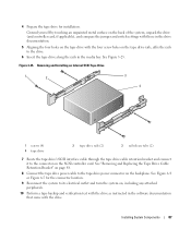
... electrical outlet and turn the system on, including any attached peripherals. 10 Perform a tape backup and verification test with the drive as instructed in the software documentation that came with the four screw holes on the tape drive rails, affix the rails to the drive. 6 Insert the tape drive along the...
... electrical outlet and turn the system on, including any attached peripherals. 10 Perform a tape backup and verification test with the drive as instructed in the software documentation that came with the four screw holes on the tape drive rails, affix the rails to the drive. 6 Insert the tape drive along the...
Hardware Owner's Manual (PDF)
Page 111
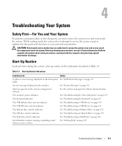
See the systems management software documentation. See "Troubleshooting the Keyboard" on page 19. The USB diskette drive activity indicator. While working inside the system. Start-Up Routine Indications Look/listen ... page 28. Troubleshooting Your System 111 See "System Messages" on page 123. See "Troubleshooting a USB Device" on page 115. Alert messages from the systems management software. The hard-drive activity indicator. Table 4-1.
See the systems management software documentation. See "Troubleshooting the Keyboard" on page 19. The USB diskette drive activity indicator. While working inside the system. Start-Up Routine Indications Look/listen ... page 28. Troubleshooting Your System 111 See "System Messages" on page 123. See "Troubleshooting a USB Device" on page 115. Alert messages from the systems management software. The hard-drive activity indicator. Table 4-1.
Hardware Owner's Manual (PDF)
Page 118
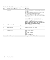
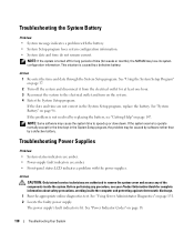
... against electrostatic discharge. 1 Run the appropriate online diagnostics test. See "Power Indicator Codes" on page 131. 2 Locate the faulty power supply. NOTE: Some software may be caused by software rather than by replacing the battery, see your Product Information Guide for the time kept in the System Setup program, replace the battery...
... against electrostatic discharge. 1 Run the appropriate online diagnostics test. See "Power Indicator Codes" on page 131. 2 Locate the faulty power supply. NOTE: Some software may be caused by software rather than by replacing the battery, see your Product Information Guide for the time kept in the System Setup program, replace the battery...
Hardware Owner's Manual (PDF)
Page 119
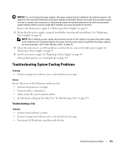
The system is amber. • Systems management software issues a fan-related error message. • Front panel LCD indicates a problem with only one power supply at a time in the redundant mode when two power ... the indicators to see "Getting Help" on page 63. 3 Ensure that none of time with the fan. Troubleshooting System Cooling Problems Problem • Systems management software issues a fan-related error message. Action Ensure that the power supply is resolved. See "Removing a Power Supply" on page 147. If the problem persists, see...
The system is amber. • Systems management software issues a fan-related error message. • Front panel LCD indicates a problem with only one power supply at a time in the redundant mode when two power ... the indicators to see "Getting Help" on page 63. 3 Ensure that none of time with the fan. Troubleshooting System Cooling Problems Problem • Systems management software issues a fan-related error message. Action Ensure that the power supply is resolved. See "Removing a Power Supply" on page 147. If the problem persists, see...

Hardware Owner's Manual (PDF)
Page 120
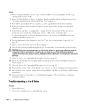
... is on page 65. See "System Fans" on , only replace one fan at a time. 3 Locate the faulty fan indicated by the LCD display or diagnostic software. Action CAUTION: Only trained service technicians are authorized to remove the system cover and access any of the components inside the system. For the identification...
... is on page 65. See "System Fans" on , only replace one fan at a time. 3 Locate the faulty fan indicated by the LCD display or diagnostic software. Action CAUTION: Only trained service technicians are authorized to remove the system cover and access any of the components inside the system. For the identification...

Hardware Owner's Manual (PDF)
Page 123
... outlet. 5 Open the system. Troubleshooting an External SCSI Tape Drive Problem • Defective tape drive • Defective tape cartridge • Missing or corrupted tape-backup software or tape drive device driver • Defective SCSI controller Troubleshooting Your System 123 If the problem is properly connected to the electrical outlet, and turn...
... outlet. 5 Open the system. Troubleshooting an External SCSI Tape Drive Problem • Defective tape drive • Defective tape cartridge • Missing or corrupted tape-backup software or tape drive device driver • Defective SCSI controller Troubleshooting Your System 123 If the problem is properly connected to the electrical outlet, and turn...
Hardware Owner's Manual (PDF)
Page 124
... the system to the electrical outlet, and turn on the system, including attached peripherals. 13 If the problem is firmly seated in the tape-backup software documentation. 4 Ensure that the tape drive's interface/DC power cable is connected to connect the drive. See "Front Bezel" on page 76. 11 Close the... assistance. CAUTION: Only trained service technicians are configured correctly. See "Removing and Installing an Internal SCSI Tape Drive" on page 86. 3 Reinstall the tape-backup software as instructed in its connector.
... the system to the electrical outlet, and turn on the system, including attached peripherals. 13 If the problem is firmly seated in the tape-backup software documentation. 4 Ensure that the tape drive's interface/DC power cable is connected to connect the drive. See "Front Bezel" on page 76. 11 Close the... assistance. CAUTION: Only trained service technicians are configured correctly. See "Removing and Installing an Internal SCSI Tape Drive" on page 86. 3 Reinstall the tape-backup software as instructed in its connector.


