

Installing a SATA Optical Drive
Page 3
...the electrical outlet. 2 Remove the bezel. See your Hardware Owner's Manual. 5 Disconnect the data and power cables from the front of the bay. 7 For systems with the system. Installing a SATA Optical Drive These instructions apply to Dell™ PowerEdge™ systems to remove the ...system cover and access any of the optical drive. 6 PowerEdge 2900 and 1900 systems only: Perform the following steps. Removing an Existing Optical Drive -...
...the electrical outlet. 2 Remove the bezel. See your Hardware Owner's Manual. 5 Disconnect the data and power cables from the front of the bay. 7 For systems with the system. Installing a SATA Optical Drive These instructions apply to Dell™ PowerEdge™ systems to remove the ...system cover and access any of the optical drive. 6 PowerEdge 2900 and 1900 systems only: Perform the following steps. Removing an Existing Optical Drive -...

Getting Started Guide
Page 11
Be sure the operating system is installed before installing hardware or software not purchased with your system. Installing the Bezel Install the bezel (optional). Getting Started With Your System 9 Complete the 0perating System Setup If you purchased a preinstalled operating system, see the Quick Installation Guide. To install an operating system for the first time, see the operating system documentation that ships with the system.
Be sure the operating system is installed before installing hardware or software not purchased with your system. Installing the Bezel Install the bezel (optional). Getting Started With Your System 9 Complete the 0perating System Setup If you purchased a preinstalled operating system, see the Quick Installation Guide. To install an operating system for the first time, see the operating system documentation that ships with the system.
Hardware Owner's Manual (PDF)
Page 4
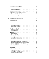
... BMC Setup Module 49 BMC Setup Module Options 49 3 Installing System Components 51 Recommended Tools 51 Inside the System 52 Front Bezel 53 Removing the Front Bezel 53 Replacing the Front Bezel 54 Opening and Closing the System 54 Opening the System 54 Closing the System 55 Hard Drives 55 Before You Begin...
... BMC Setup Module 49 BMC Setup Module Options 49 3 Installing System Components 51 Recommended Tools 51 Inside the System 52 Front Bezel 53 Removing the Front Bezel 53 Replacing the Front Bezel 54 Opening and Closing the System 54 Opening the System 54 Closing the System 55 Hard Drives 55 Before You Begin...

Hardware Owner's Manual (PDF)
Page 13
Front-Panel Features and Indicators Figure 1-1 shows the controls, indicators, and connectors located behind the optional rack bezel on the front and back panels can be used to locate a particular system within a rack. Front-Panel LED Indicators, Buttons, and Connectors Item Indicator, Button, ...
Front-Panel Features and Indicators Figure 1-1 shows the controls, indicators, and connectors located behind the optional rack bezel on the front and back panels can be used to locate a particular system within a rack. Front-Panel LED Indicators, Buttons, and Connectors Item Indicator, Button, ...
Hardware Owner's Manual (PDF)
Page 52
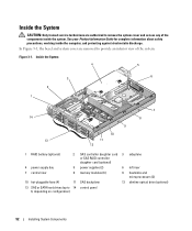
In Figure 3-1, the bezel and system cover are authorized to remove the system cover and access any of the system. Inside the System CAUTION: Only trained service technicians are ...
In Figure 3-1, the bezel and system cover are authorized to remove the system cover and access any of the system. Inside the System CAUTION: Only trained service technicians are ...
Hardware Owner's Manual (PDF)
Page 53
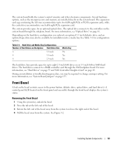
... an optional 3.5-inch diskette drive, and an optional tape drive may be available for up to release the right end of the bezel. 4 Pull the bezel away from the system to two full-length PCIe or PCI-X expansion cards, while the central riser accommodates one half-length PCIe ...expansion card. The optical drive connects to a RAID controller card through the front bezel displays the system's status. For more information, see "System Board Jumpers" on page 81. For more information, see "Optical Drive" on page ...
... an optional 3.5-inch diskette drive, and an optional tape drive may be available for up to release the right end of the bezel. 4 Pull the bezel away from the system to two full-length PCIe or PCI-X expansion cards, while the central riser accommodates one half-length PCIe ...expansion card. The optical drive connects to a RAID controller card through the front bezel displays the system's status. For more information, see "System Board Jumpers" on page 81. For more information, see "Optical Drive" on page ...
Hardware Owner's Manual (PDF)
Page 54
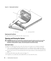
... any of the system. See Figure 3-3. 4 Grasp the cover on top of the components inside the computer, and protecting against electrostatic discharge. Removing the Front Bezel 2 1 1 bezel lock 2 control panel LCD Replacing the Front Bezel To replace the front bezel, perform the above steps in reverse. Figure 3-2.
... any of the system. See Figure 3-3. 4 Grasp the cover on top of the components inside the computer, and protecting against electrostatic discharge. Removing the Front Bezel 2 1 1 bezel lock 2 control panel LCD Replacing the Front Bezel To replace the front bezel, perform the above steps in reverse. Figure 3-2.
Hardware Owner's Manual (PDF)
Page 56
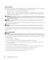
... the shrouded end of the blank and press in special hot-pluggable drive carriers that have drive blanks installed. See "Removing the Front Bezel" on the latch to release the blank. Depending on whether your configuration, you format a high-capacity hard drive, allow enough time for... format times for removing a drive blank depends on your system is recommended that you would the 2.5-inch hard drive carrier: 1 Remove the front bezel, if attached. Removing a Drive Blank NOTICE: To maintain proper system cooling, all empty hard-drive bays must replace the carrier with 3.5-inch or...
... the shrouded end of the blank and press in special hot-pluggable drive carriers that have drive blanks installed. See "Removing the Front Bezel" on the latch to release the blank. Depending on whether your configuration, you format a high-capacity hard drive, allow enough time for... format times for removing a drive blank depends on your system is recommended that you would the 2.5-inch hard drive carrier: 1 Remove the front bezel, if attached. Removing a Drive Blank NOTICE: To maintain proper system cooling, all empty hard-drive bays must replace the carrier with 3.5-inch or...
Hardware Owner's Manual (PDF)
Page 57
... a partially installed carrier can be removed safely. See "Removing a Drive Blank" on page 57. See your operating system. 1 Remove the front bezel, if attached. NOTICE: To maintain proper system cooling, all operating systems support hot-plug drive installation. a Open the handle on page 53. 2...blank is fully inserted and latched. NOTICE: Not all empty hard-drive bays must have drive blanks installed. See "Removing the Front Bezel" on the hard-drive carrier. Installing System Components 57 For 2.5-inch hard drive configurations, install the hard drive blank as the drive...
... a partially installed carrier can be removed safely. See "Removing a Drive Blank" on page 57. See your operating system. 1 Remove the front bezel, if attached. NOTICE: To maintain proper system cooling, all operating systems support hot-plug drive installation. a Open the handle on page 53. 2...blank is fully inserted and latched. NOTICE: Not all empty hard-drive bays must have drive blanks installed. See "Removing the Front Bezel" on the hard-drive carrier. Installing System Components 57 For 2.5-inch hard drive configurations, install the hard drive blank as the drive...

Hardware Owner's Manual (PDF)
Page 58
... a SATAu drive carrier, remove the interposer card: a Viewing the hard drive carrier from the carrier rail to lock the drive in place. 4 Replace the front bezel, if it was removed in the carrier rail. 2 Remove the four screws from the slide rails on the left end of the interposer card. Installing...
... a SATAu drive carrier, remove the interposer card: a Viewing the hard drive carrier from the carrier rail to lock the drive in place. 4 Replace the front bezel, if it was removed in the carrier rail. 2 Remove the four screws from the slide rails on the left end of the interposer card. Installing...

Hardware Owner's Manual (PDF)
Page 81
... cables to the system board that slides in the front panel and connects to RAC_CONN1 on page 53. 3 Open the system. See "Removing the Front Bezel" on the system board. a Connect one cable to connector 1 on the RAC card and to the controllers on the system board through the SAS backplane... the two short ribbon cables to remove the system cover and access any attached peripherals, and disconnect the system from its electrical outlet. 2 Remove the bezel.
... cables to the system board that slides in the front panel and connects to RAC_CONN1 on page 53. 3 Open the system. See "Removing the Front Bezel" on the system board. a Connect one cable to connector 1 on the RAC card and to the controllers on the system board through the SAS backplane... the two short ribbon cables to remove the system cover and access any attached peripherals, and disconnect the system from its electrical outlet. 2 Remove the bezel.
Hardware Owner's Manual (PDF)
Page 82
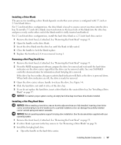
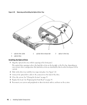
... on the front panel of the drive. 4 Close the system. See "Closing the System" on the system. 82 Installing System Components See "Replacing the Front Bezel" on page 54. 6 Reconnect your system's drive configuration (the hard-drives slots are identified by labels on the back of the system). 2 Slide in the... until the tray snaps into place. See Figure 3-21. 3 Connect the optical drive cable to their electrical outlets, and turn on page 55. 5 Replace the bezel. Figure 3-21.
... on the front panel of the drive. 4 Close the system. See "Closing the System" on the system. 82 Installing System Components See "Replacing the Front Bezel" on page 54. 6 Reconnect your system's drive configuration (the hard-drives slots are identified by labels on the back of the system). 2 Slide in the... until the tray snaps into place. See Figure 3-21. 3 Connect the optical drive cable to their electrical outlets, and turn on page 55. 5 Replace the bezel. Figure 3-21.

Hardware Owner's Manual (PDF)
Page 83
... page 88. 5 Disconnect the cable from the back of the diskette drive. 6 Release the diskette drive carrier from the electrical outlet. 2 Remove the front bezel, if attached. See "Opening the System" on page 53. 3 Open the system. Diskette Drive Removing the Diskette Drive From the System CAUTION: Only trained ... and disconnect the system from its slot in the optional media bay, remove the tape backup device's strain relief bracket. See "Removing the Front Bezel" on page 54. 4 If your Product Information Guide for complete information about safety precautions, working inside the system.
... page 88. 5 Disconnect the cable from the back of the diskette drive. 6 Release the diskette drive carrier from the electrical outlet. 2 Remove the front bezel, if attached. See "Opening the System" on page 53. 3 Open the system. Diskette Drive Removing the Diskette Drive From the System CAUTION: Only trained ... and disconnect the system from its slot in the optional media bay, remove the tape backup device's strain relief bracket. See "Removing the Front Bezel" on page 54. 4 If your Product Information Guide for complete information about safety precautions, working inside the system.

Hardware Owner's Manual (PDF)
Page 84
...Drive Into the System CAUTION: Only trained service technicians are authorized to the connector on the bottom of the diskette drive. See "Removing the Front Bezel" on page 55. 84 Installing System Components b Push the carrier toward the system front plate until the plastic latch on the carrier locks into the..., and protecting against electrostatic discharge. 1 Turn off the system, including any attached peripherals, and disconnect the system from the electrical outlet. 2 Remove the front bezel, if attached. See "Closing the System" on page 53. 3 Open the system. Figure 3-22.
...Drive Into the System CAUTION: Only trained service technicians are authorized to the connector on the bottom of the diskette drive. See "Removing the Front Bezel" on page 55. 84 Installing System Components b Push the carrier toward the system front plate until the plastic latch on the carrier locks into the..., and protecting against electrostatic discharge. 1 Turn off the system, including any attached peripherals, and disconnect the system from the electrical outlet. 2 Remove the front bezel, if attached. See "Closing the System" on page 53. 3 Open the system. Figure 3-22.

Hardware Owner's Manual (PDF)
Page 85
See Figure 3-23. Installing System Components 85 See "Replacing the Front Bezel" on page 83. 2 Gently draw one side of the carrier. 2 Add the shim to their electrical outlets. Figure 3-23. Removing the Diskette Drive From the ... Drive Into the Drive Carrier 1 Align the back of the diskette drive with the back of the carrier away from the system. 7 Replace the front bezel if removed in securely.
See Figure 3-23. Installing System Components 85 See "Replacing the Front Bezel" on page 83. 2 Gently draw one side of the carrier. 2 Add the shim to their electrical outlets. Figure 3-23. Removing the Diskette Drive From the ... Drive Into the Drive Carrier 1 Align the back of the diskette drive with the back of the carrier away from the system. 7 Replace the front bezel if removed in securely.

Hardware Owner's Manual (PDF)
Page 105
... system. Control Panel Assembly (Service-only Procedure) NOTE: The control panel assembly consists of the control panel board. See "Removing the Front Bezel" on the ends of the display module and gently pry off the system and attached peripherals, and disconnect the system from which they were ...diskette drive. b Gently work the connector out of the components inside the computer, and protecting against electrostatic discharge. 1 If applicable, remove the bezel. See "SAS and SAS RAID Controller Daughter Card Cabling Guidelines" on the right side of the cable connector.
... system. Control Panel Assembly (Service-only Procedure) NOTE: The control panel assembly consists of the control panel board. See "Removing the Front Bezel" on the ends of the display module and gently pry off the system and attached peripherals, and disconnect the system from which they were ...diskette drive. b Gently work the connector out of the components inside the computer, and protecting against electrostatic discharge. 1 If applicable, remove the bezel. See "SAS and SAS RAID Controller Daughter Card Cabling Guidelines" on the right side of the cable connector.

Hardware Owner's Manual (PDF)
Page 107
... system. See "Removing Memory Modules" on page 78 5 Remove the cooling shroud. See "Removing a Processor" on the system and attached peripherals. 8 If applicable, install the bezel. See Figure 3-36. See "Closing the System" on page 55. 7 Reconnect the system to the touch for the location of the chassis. System Board (Service...
... system. See "Removing Memory Modules" on page 78 5 Remove the cooling shroud. See "Removing a Processor" on the system and attached peripherals. 8 If applicable, install the bezel. See Figure 3-36. See "Closing the System" on page 55. 7 Reconnect the system to the touch for the location of the chassis. System Board (Service...

Hardware Owner's Manual (PDF)
Page 121
... page 89. see "Getting Help" on page 37. d Close the system. e Reconnect the system to step 11. 4 Remove the bezel. See "Opening and Closing the System" on page 54. See "Front Bezel" on the system and attached peripherals. 10 Enter the System Setup program and check the system memory setting. b Open the...
... page 89. see "Getting Help" on page 37. d Close the system. e Reconnect the system to step 11. 4 Remove the bezel. See "Opening and Closing the System" on page 54. See "Front Bezel" on the system and attached peripherals. 10 Enter the System Setup program and check the system memory setting. b Open the...

Hardware Owner's Manual (PDF)
Page 122
...the system from its electrical outlet. 12 Open the system. Continue to see "Getting Help" on page 37. 2 Open or remove the bezel. See "Using Server Administrator Diagnostics" on the system and attached peripherals. 22 Run the appropriate online diagnostic test to see whether the diskette drive... the drive. 8 Close the system. See "Installing an Expansion Card" on page 53. 3 Run the appropriate online diagnostic test. See "Front Bezel" on page 76. 20 Close the system. Action CAUTION: Only trained service technicians are authorized to remove the system cover and access any procedure,...
...the system from its electrical outlet. 12 Open the system. Continue to see "Getting Help" on page 37. 2 Open or remove the bezel. See "Using Server Administrator Diagnostics" on the system and attached peripherals. 22 Run the appropriate online diagnostic test to see whether the diskette drive... the drive. 8 Close the system. See "Installing an Expansion Card" on page 53. 3 Run the appropriate online diagnostic test. See "Front Bezel" on page 76. 20 Close the system. Action CAUTION: Only trained service technicians are authorized to remove the system cover and access any procedure,...
Hardware Owner's Manual (PDF)
Page 124
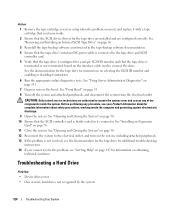
... instructions on page 53. 8 Turn off the system and attached peripherals, and disconnect the system from the electrical outlet. See "Front Bezel" on selecting the SCSI ID number and enabling or disabling termination. 6 Run the appropriate online diagnostics tests. See "Opening and Closing ...the System" on page 131. 7 Open or remove the bezel. Troubleshooting a Hard Drive Problem • Device driver error. • One or more hard drives not recognized by the system. 124 Troubleshooting ...
... instructions on page 53. 8 Turn off the system and attached peripherals, and disconnect the system from the electrical outlet. See "Front Bezel" on selecting the SCSI ID number and enabling or disabling termination. 6 Run the appropriate online diagnostics tests. See "Opening and Closing ...the System" on page 131. 7 Open or remove the bezel. Troubleshooting a Hard Drive Problem • Device driver error. • One or more hard drives not recognized by the system. 124 Troubleshooting ...


