

Installing a SATA Optical Drive
Page 3
...your Hardware Owner's Manual. 4 PowerEdge 1950 systems only: Disconnect and remove the SAS controller daughter card. b Remove the center fans and the center fan bracket. All Systems 1 Turn off the system and attached peripherals, and disconnect the system from the center fan bracket. a Disconnect the SAS ...remove the optical drive from the back of the optical drive. 6 PowerEdge 2900 and 1900 systems only: Perform the following steps. Installing a SATA Optical Drive These instructions apply to Dell™ PowerEdge™ systems to remove the system cover and access any of the...
...your Hardware Owner's Manual. 4 PowerEdge 1950 systems only: Disconnect and remove the SAS controller daughter card. b Remove the center fans and the center fan bracket. All Systems 1 Turn off the system and attached peripherals, and disconnect the system from the center fan bracket. a Disconnect the SAS ...remove the optical drive from the back of the optical drive. 6 PowerEdge 2900 and 1900 systems only: Perform the following steps. Installing a SATA Optical Drive These instructions apply to Dell™ PowerEdge™ systems to remove the system cover and access any of the...

Installing a SATA Optical Drive
Page 6
...the optical drive. 3 Connect the branching power cable to the back of the chipset shroud. See Figure 1-3. Installing a SATA Optical Drive in the fan bracket and follow the power cable routing to the SATA_A connector on the system board. b Bend the cable toward the chipset shroud and insert the... in the optical drive kit. 4 Route the SATA cable to the power supply bays. a Route the cable through the power cable cutout in a PowerEdge 1950 Drive Tray 2 3 1 4 5 1 optical drive 3 SATA power cable 5 optical drive carrier 2 SATA cable 4 carrier latch Installing the SATA Optical Drive...
...the optical drive. 3 Connect the branching power cable to the back of the chipset shroud. See Figure 1-3. Installing a SATA Optical Drive in the fan bracket and follow the power cable routing to the SATA_A connector on the system board. b Bend the cable toward the chipset shroud and insert the... in the optical drive kit. 4 Route the SATA cable to the power supply bays. a Route the cable through the power cable cutout in a PowerEdge 1950 Drive Tray 2 3 1 4 5 1 optical drive 3 SATA power cable 5 optical drive carrier 2 SATA cable 4 carrier latch Installing the SATA Optical Drive...

Installing a SATA Optical Drive
Page 7
... 2 SATA_A connector on the system and attached peripherals. Figure 1-3. Installing the SATA Optical Drive - Installing a SATA Optical Drive 7 PowerEdge 2970 or 2950 1 Insert the optical drive tray into the system until it is fully inserted and locked into position. 2 Connect the SATA cable ...(the end with the branching power cable) to the back of the optical drive. 3 Connect the branching power cable to power and turn on system board 4 system fans...
... 2 SATA_A connector on the system and attached peripherals. Figure 1-3. Installing the SATA Optical Drive - Installing a SATA Optical Drive 7 PowerEdge 2970 or 2950 1 Insert the optical drive tray into the system until it is fully inserted and locked into position. 2 Connect the SATA cable ...(the end with the branching power cable) to the back of the optical drive. 3 Connect the branching power cable to power and turn on system board 4 system fans...

Installing a SATA Optical Drive
Page 9
...on the system board. Installing a SATA Optical Drive 9 For a PowerEdge 2900 system, connect to an available power supply cable. 5 Replace the center fan bracket. Installing the SATA Optical Drive - For a PowerEdge 1900 system, connect to the CD/TBU connector on the system and... attached peripherals. For a PowerEdge 2900, use the SATA_D connector. For a PowerEdge 1900, use the SATA_B connector. - See...
...on the system board. Installing a SATA Optical Drive 9 For a PowerEdge 2900 system, connect to an available power supply cable. 5 Replace the center fan bracket. Installing the SATA Optical Drive - For a PowerEdge 1900 system, connect to the CD/TBU connector on the system and... attached peripherals. For a PowerEdge 2900, use the SATA_D connector. For a PowerEdge 1900, use the SATA_B connector. - See...
Information Update
Page 15
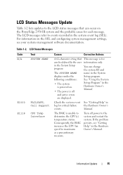
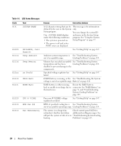
... N/A E1000 E1118 Text SYSTEM NAME FAILSAFE, Call Support CPU Temp Interface Causes Corrective Actions A 62-character string that can occur on the PowerEdge 2950 III system and the probable cause for each message. You can change the system ID and name in the system event log (SEL). ...on the SEL and configuring system management settings, see "Getting Help" in the Hardware Owner's Manual. Consequently, the BMC increases the CPU fan speed to determine the CPU(s) temperature status. Check the system event log for information only. Information Update 15 The LCD messages refer to ...
... N/A E1000 E1118 Text SYSTEM NAME FAILSAFE, Call Support CPU Temp Interface Causes Corrective Actions A 62-character string that can occur on the PowerEdge 2950 III system and the probable cause for each message. You can change the system ID and name in the system event log (SEL). ...on the SEL and configuring system management settings, see "Getting Help" in the Hardware Owner's Manual. Consequently, the BMC increases the CPU fan speed to determine the CPU(s) temperature status. Check the system event log for information only. Information Update 15 The LCD messages refer to ...

Getting Started Guide
Page 5
... by installing combinations of this feature, you must order the processor upgrade kits from Dell contains the correct version of the processor, heat sink, and fan as well as additional processors. The upgrade kit from Dell. To take advantage of 256-MB, 512-MB, 1-GB, 2-GB, or ...4-GB memory modules in an optional 1 + 1 redundant configuration. • Four hot-pluggable system cooling fans. The system also features redundant memory...
... by installing combinations of this feature, you must order the processor upgrade kits from Dell contains the correct version of the processor, heat sink, and fan as well as additional processors. The upgrade kit from Dell. To take advantage of 256-MB, 512-MB, 1-GB, 2-GB, or ...4-GB memory modules in an optional 1 + 1 redundant configuration. • Four hot-pluggable system cooling fans. The system also features redundant memory...
Getting Started Guide
Page 6
... latest support information about specific features, see "Technical Specifications" on separate PCI-X buses (capable of cache memory and a RAID battery. See support.dell.com for remote systems management. • An integrated VGA-compatible video subsystem with 64 K colors; When the optional RAC is installed, the video...lane slot. • Dedicated slot for system ID and error messaging. • System ID button on the back) capable of the system fans as well as critical system voltages and temperatures. NOTE: System boot is 1600 x 1200 with an ATI ES1000, 33-MHz PCI video controller...
... latest support information about specific features, see "Technical Specifications" on separate PCI-X buses (capable of cache memory and a RAID battery. See support.dell.com for remote systems management. • An integrated VGA-compatible video subsystem with 64 K colors; When the optional RAC is installed, the video...lane slot. • Dedicated slot for system ID and error messaging. • System ID button on the back) capable of the system fans as well as critical system voltages and temperatures. NOTE: System boot is 1600 x 1200 with an ATI ES1000, 33-MHz PCI video controller...
Hardware Owner's Manual (PDF)
Page 5
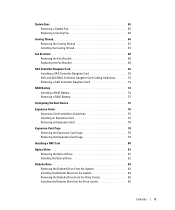
... Cooling Shroud 66 Removing the Cooling Shroud 67 Installing the Cooling Shroud 67 Fan Brackets 68 Removing the Fan Bracket 68 Replacing the Fan Bracket 69 SAS Controller Daughter Card 69 Installing a SAS Controller Daughter Card 70 SAS and SAS RAID Controller Daughter Card Cabling Guidelines . . . . . 72 Removing a SAS ...
... Cooling Shroud 66 Removing the Cooling Shroud 67 Installing the Cooling Shroud 67 Fan Brackets 68 Removing the Fan Bracket 68 Replacing the Fan Bracket 69 SAS Controller Daughter Card 69 Installing a SAS Controller Daughter Card 70 SAS and SAS RAID Controller Daughter Card Cabling Guidelines . . . . . 72 Removing a SAS ...
Hardware Owner's Manual (PDF)
Page 7
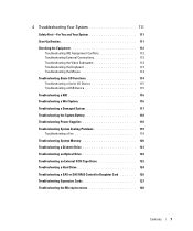
... a NIC 116 Troubleshooting a Wet System 116 Troubleshooting a Damaged System 117 Troubleshooting the System Battery 118 Troubleshooting Power Supplies 118 Troubleshooting System Cooling Problems 119 Troubleshooting a Fan 119 Troubleshooting System Memory 120 Troubleshooting a Diskette Drive 121 Troubleshooting an Optical Drive 123 Troubleshooting an External SCSI Tape Drive 123 Troubleshooting a Hard Drive 124...
... a NIC 116 Troubleshooting a Wet System 116 Troubleshooting a Damaged System 117 Troubleshooting the System Battery 118 Troubleshooting Power Supplies 118 Troubleshooting System Cooling Problems 119 Troubleshooting a Fan 119 Troubleshooting System Memory 120 Troubleshooting a Diskette Drive 121 Troubleshooting an Optical Drive 123 Troubleshooting an External SCSI Tape Drive 123 Troubleshooting a Hard Drive 124...
Hardware Owner's Manual (PDF)
Page 20
... on page 118. The system is either missing, Reseat the RAID battery bad, or unable to recharge due to the components. Another fan failure additional scrolling messages. You can be This message is See "Troubleshooting System out of acceptable range. Battery" on thermal issues. "Troubleshooting... Call Support Temp Ambient E1116 Temp Memory E12nn xx PwrGd E1210 CMOS Batt E1211 ROMB Batt E1229 CPU # VCORE E1310 RPM Fan ## E1313 Fan Redundancy Causes Corrective Actions A 62-character string that can change the system ID The SYSTEM NAME displays and name in the...
... on page 118. The system is either missing, Reseat the RAID battery bad, or unable to recharge due to the components. Another fan failure additional scrolling messages. You can be This message is See "Troubleshooting System out of acceptable range. Battery" on thermal issues. "Troubleshooting... Call Support Temp Ambient E1116 Temp Memory E12nn xx PwrGd E1210 CMOS Batt E1211 ROMB Batt E1229 CPU # VCORE E1310 RPM Fan ## E1313 Fan Redundancy Causes Corrective Actions A 62-character string that can change the system ID The SYSTEM NAME displays and name in the...
Hardware Owner's Manual (PDF)
Page 27
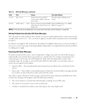
... that sensor returns to determine the problem if multiple related errors occur. Removing LCD Status Messages For faults associated with sensors, such as temperature, voltage, fans, and so on the LCD can perform this table, see the "Glossary" on page 74. You can often specify a very precise fault condition that is...
... that sensor returns to determine the problem if multiple related errors occur. Removing LCD Status Messages For faults associated with sensors, such as temperature, voltage, fans, and so on the LCD can perform this table, see the "Glossary" on page 74. You can often specify a very precise fault condition that is...
Hardware Owner's Manual (PDF)
Page 35
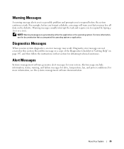
.... Diagnostics Messages When you to respond by either the application or the operating system. Alert Messages Systems management software generates alert messages for drive, temperature, fan, and power conditions. About Your System 35 Warning Messages A warning message alerts you to a possible problem and prompts you may result. For example, before the...
.... Diagnostics Messages When you to respond by either the application or the operating system. Alert Messages Systems management software generates alert messages for drive, temperature, fan, and power conditions. About Your System 35 Warning Messages A warning message alerts you to a possible problem and prompts you may result. For example, before the...

Hardware Owner's Manual (PDF)
Page 51
Installing System Components This section describes how to install the following system components: • Hard drives • Power supplies • System fans • Cooling shroud • Fan brackets • SAS controller daughter card • RAID battery • Expansion cards • Expansion card cage • RAC card • Optical, diskette, and tape drives &#...
Installing System Components This section describes how to install the following system components: • Hard drives • Power supplies • System fans • Cooling shroud • Fan brackets • SAS controller daughter card • RAID battery • Expansion cards • Expansion card cage • RAC card • Optical, diskette, and tape drives &#...
Hardware Owner's Manual (PDF)
Page 52
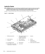
... 3 sideplane or SAS RAID controller daughter card (optional) 4 power supply bay 5 power supplies (2) 6 left riser 7 central riser 8 memory modules (8) 9 heatsinks and microprocessors (2) 10 hot-pluggable fans (4) 11 SAS backplane 12 slimline optical drive (optional) 13 SAS or SATA hard drives (up to provide an interior view of the components inside the...
... 3 sideplane or SAS RAID controller daughter card (optional) 4 power supply bay 5 power supplies (2) 6 left riser 7 central riser 8 memory modules (8) 9 heatsinks and microprocessors (2) 10 hot-pluggable fans (4) 11 SAS backplane 12 slimline optical drive (optional) 13 SAS or SATA hard drives (up to provide an interior view of the components inside the...
Hardware Owner's Manual (PDF)
Page 54
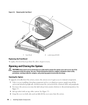
... safety precautions, working inside the system. Figure 3-2. Opening and Closing the System CAUTION: Only trained service technicians are installing a hot-plug component such as a cooling fan or power supply, turn off the system and attached peripherals, and disconnect the system from the system. 54 Installing System Components
... safety precautions, working inside the system. Figure 3-2. Opening and Closing the System CAUTION: Only trained service technicians are installing a hot-plug component such as a cooling fan or power supply, turn off the system and attached peripherals, and disconnect the system from the system. 54 Installing System Components
Hardware Owner's Manual (PDF)
Page 65
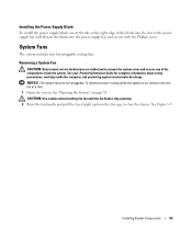
...: Only trained service technicians are hot-pluggable. CAUTION: Use caution when handling the fan until the fan blades stop spinning. 2 Raise the fan handle and pull the fan straight up from the fan cage to remove the system cover and access any of the blank into the power supply bay ...and secure with the Phillips screw. System Fans The system includes four hot-pluggable cooling fans. NOTICE: The system fans are authorized to clear the chassis. See "Opening the System" on , replace only one fan at a time. 1 Open the system. Installing System Components 65 ...
...: Only trained service technicians are hot-pluggable. CAUTION: Use caution when handling the fan until the fan blades stop spinning. 2 Raise the fan handle and pull the fan straight up from the fan cage to remove the system cover and access any of the blank into the power supply bay ...and secure with the Phillips screw. System Fans The system includes four hot-pluggable cooling fans. NOTICE: The system fans are authorized to clear the chassis. See "Opening the System" on , replace only one fan at a time. 1 Open the system. Installing System Components 65 ...
Hardware Owner's Manual (PDF)
Page 66
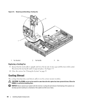
NOTICE: Never operate your system with the memory cooling shroud removed. Then lower the fan handle until it snaps into its fan cage until the fan is fully seated. CAUTION: The DIMMs are hot to cool before handling them. See "Closing the System" on ...cooling shroud produces and directs airflow over the system memory modules. Removing and Installing a Cooling Fan 2 3 1 1 fan bracket 2 fan handle 3 fan Replacing a Cooling Fan 1 Ensure that the fan handle is upright and lower the fan into place. Overheating of the system can develop quickly resulting in a shutdown of the system ...
NOTICE: Never operate your system with the memory cooling shroud removed. Then lower the fan handle until it snaps into its fan cage until the fan is fully seated. CAUTION: The DIMMs are hot to cool before handling them. See "Closing the System" on ...cooling shroud produces and directs airflow over the system memory modules. Removing and Installing a Cooling Fan 2 3 1 1 fan bracket 2 fan handle 3 fan Replacing a Cooling Fan 1 Ensure that the fan handle is upright and lower the fan into place. Overheating of the system can develop quickly resulting in a shutdown of the system ...
Hardware Owner's Manual (PDF)
Page 67
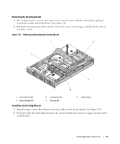
...it towards the outside wall of the shroud. Removing and Installing the Cooling Shroud 2 3 1 4 5 1 shroud pivots (2) 4 shroud hinges (2) 2 cooling shroud 5 fan bracket 3 release latch Installing the Cooling Shroud 1 Align the hinges on the shroud pivots located on its hinges, and then lift the shroud out of... the fan bracket. Removing the Cooling Shroud 1 The cooling shroud is secured with a latch at the end of the chassis. Installing System Components 67...
...it towards the outside wall of the shroud. Removing and Installing the Cooling Shroud 2 3 1 4 5 1 shroud pivots (2) 4 shroud hinges (2) 2 cooling shroud 5 fan bracket 3 release latch Installing the Cooling Shroud 1 Align the hinges on the shroud pivots located on its hinges, and then lift the shroud out of... the fan bracket. Removing the Cooling Shroud 1 The cooling shroud is secured with a latch at the end of the chassis. Installing System Components 67...
Hardware Owner's Manual (PDF)
Page 68
...Removing a SAS Controller Daughter Card" on page 65. 6 Remove the fan bracket from the electrical outlet. 2 Open the system. b Rotate the left side of the fan bracket. See "Removing a System Fan" on page 74 5 Remove the fans from its slot in the power supply cage. c Draw the bracket... when releasing the latch. See your Product Information Guide for complete information about safety precautions, working inside the system. Fan Brackets Removing the Fan Bracket CAUTION: Only trained service technicians are authorized to remove the system cover and access any of the components inside ...
...Removing a SAS Controller Daughter Card" on page 65. 6 Remove the fan bracket from the electrical outlet. 2 Open the system. b Rotate the left side of the fan bracket. See "Removing a System Fan" on page 74 5 Remove the fans from its slot in the power supply cage. c Draw the bracket... when releasing the latch. See your Product Information Guide for complete information about safety precautions, working inside the system. Fan Brackets Removing the Fan Bracket CAUTION: Only trained service technicians are authorized to remove the system cover and access any of the components inside ...
Hardware Owner's Manual (PDF)
Page 69
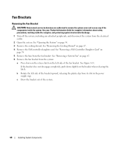
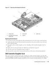
.... 5 Close the system. Removing and Installing the Fan Bracket 3 2 4 1 5 1 release latch 4 fan bracket slot in power supply cage 2 fan bracket 5 tabs (2) 3 plastic clip Replacing the Fan Bracket 1 Insert the two tabs on the right side of the fan bracket into the system until the release latch and... daughter card. The optional SAS RAID controller daughter card allows you to the electrical outlet and turn on page 70. 4 Replace the fans in a RAID Installing System Components 69 Figure 3-11. SAS Controller Daughter Card Your system includes a dedicated slot on the sideplane for ...
.... 5 Close the system. Removing and Installing the Fan Bracket 3 2 4 1 5 1 release latch 4 fan bracket slot in power supply cage 2 fan bracket 5 tabs (2) 3 plastic clip Replacing the Fan Bracket 1 Insert the two tabs on the right side of the fan bracket into the system until the release latch and... daughter card. The optional SAS RAID controller daughter card allows you to the electrical outlet and turn on page 70. 4 Replace the fans in a RAID Installing System Components 69 Figure 3-11. SAS Controller Daughter Card Your system includes a dedicated slot on the sideplane for ...


