
Information Update
Page 14
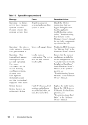
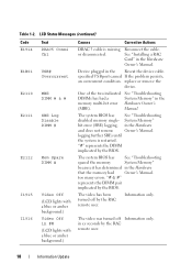
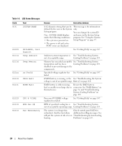
... in the Hardware Owner's Manual. 14 Information Update Warning! Update the BIOS firmware. Ensure that was logged during the error. For more information on valid memory configurations, please see the system documentation on selected drive Faulty USB device, USB medium...Troubleshooting a Hard Drive" in the SEL. System Messages (continued) Message Causes Corrective Actions Warning: A fatal error has caused system reset! No micro Micro code update failed. code update loaded See "Getting Help" in the Hardware Owner's Manual. Write fault Write fault on the technical ...
... in the Hardware Owner's Manual. 14 Information Update Warning! Update the BIOS firmware. Ensure that was logged during the error. For more information on valid memory configurations, please see the system documentation on selected drive Faulty USB device, USB medium...Troubleshooting a Hard Drive" in the SEL. System Messages (continued) Message Causes Corrective Actions Warning: A fatal error has caused system reset! No micro Micro code update failed. code update loaded See "Getting Help" in the Hardware Owner's Manual. Write fault Write fault on the technical ...
Information Update
Page 15
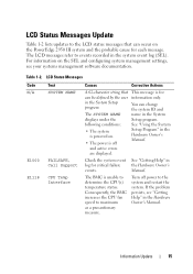
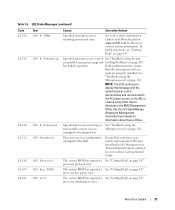
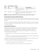
...software documentation. Information Update 15 LCD Status Messages Code N/A E1000 E1118 Text SYSTEM NAME FAILSAFE, Call Support CPU Temp Interface Causes Corrective Actions A 62-character string that can occur on the PowerEdge 2950 III system and the probable cause for each ...message. Consequently, the BMC increases the CPU fan speed to determine the CPU(s) temperature status. You can change the system ID and name in the Hardware Owner's Manual. See "Getting Help" in the Hardware Owner's Manual. Turn off and active errors...
...software documentation. Information Update 15 LCD Status Messages Code N/A E1000 E1118 Text SYSTEM NAME FAILSAFE, Call Support CPU Temp Interface Causes Corrective Actions A 62-character string that can occur on the PowerEdge 2950 III system and the probable cause for each ...message. Consequently, the BMC increases the CPU fan speed to determine the CPU(s) temperature status. You can change the system ID and name in the Hardware Owner's Manual. See "Getting Help" in the Hardware Owner's Manual. Turn off and active errors...
Information Update
Page 16
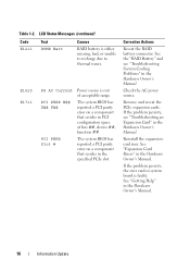
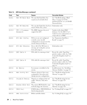
...the problem persists, the riser card or system board is out of acceptable range. Table 1-2. The system BIOS has reported a PCI parity error on a component that resides in the Hardware Owner's Manual. If the problem persists, see "Troubleshooting System Cooling Problems" in the Hardware ...Owner's Manual. LCD Status Messages (continued) Code E1211 Text ROMB Batt Causes RAID battery is either missing, bad, or unable to recharge due to thermal issues. See "Expansion Card ...
...the problem persists, the riser card or system board is out of acceptable range. Table 1-2. The system BIOS has reported a PCI parity error on a component that resides in the Hardware Owner's Manual. If the problem persists, see "Troubleshooting System Cooling Problems" in the Hardware ...Owner's Manual. LCD Status Messages (continued) Code E1211 Text ROMB Batt Causes RAID battery is either missing, bad, or unable to recharge due to thermal issues. See "Expansion Card ...
Information Update
Page 17
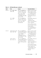
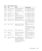
..., the riser card or system board is faulty. LCD Status Messages (continued) Code E1712 E171F Text Causes Corrective Actions PCI SERR B## D## F## The system BIOS has reported a PCI system error on a component that resides in the specified slot. PCI SERR Slot # The..., resides in PCIe see "Troubleshooting Expansion Cards" in the Hardware Owner's Manual. Owner's Manual. Table 1-2. reported a PCIe fatal error card riser. If the problem persists, see "Troubleshooting configuration space Expansion Cards" in the Hardware slot. See on a component that ...
..., the riser card or system board is faulty. LCD Status Messages (continued) Code E1712 E171F Text Causes Corrective Actions PCI SERR B## D## F## The system BIOS has reported a PCI system error on a component that resides in the specified slot. PCI SERR Slot # The..., resides in PCIe see "Troubleshooting Expansion Cards" in the Hardware Owner's Manual. Owner's Manual. Table 1-2. reported a PCIe fatal error card riser. If the problem persists, see "Troubleshooting configuration space Expansion Cards" in the Hardware slot. See on a component that ...
Information Update
Page 18
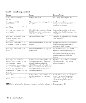
... has had Owner's Manual. The video has been turned off Information only. See "Installing a RAC Card" in the memory multi-bit error Hardware Owner's (MBE). The system BIOS has See "Troubleshooting spared the memory System Memory" because it has determined in xx seconds by the... represents the DIMM pair implicated by the BIOS. The video was turned off by the RAC remote user. 18 Information Update LCD Status Messages (continued) Code E1914 E1B01 E2110 E2111 E2112 I1915 I1916 Text DRAC5 Conn2 Cbl USB# Overcurrent MBE DIMM # & # SBE Log Disable DIMM # Mem Spare DIMM # ...
... has had Owner's Manual. The video has been turned off Information only. See "Installing a RAC Card" in the memory multi-bit error Hardware Owner's (MBE). The system BIOS has See "Troubleshooting spared the memory System Memory" because it has determined in xx seconds by the... represents the DIMM pair implicated by the BIOS. The video was turned off by the RAC remote user. 18 Information Update LCD Status Messages (continued) Code E1914 E1B01 E2110 E2111 E2112 I1915 I1916 Text DRAC5 Conn2 Cbl USB# Overcurrent MBE DIMM # & # SBE Log Disable DIMM # Mem Spare DIMM # ...

Information Update
Page 36
No micro code update loaded for processor n 请更新 BIOS Warning: The installed memory configuration is reduced. 表 1-1 信息 原因 纠正措施 Warning: ... on selected drive USB 设备、 USB USB 设备或 USB 36 信息更新 DIMM n1 和 n2 DIMM Warning: A fatal error has caused system reset!
No micro code update loaded for processor n 请更新 BIOS Warning: The installed memory configuration is reduced. 表 1-1 信息 原因 纠正措施 Warning: ... on selected drive USB 设备、 USB USB 设备或 USB 36 信息更新 DIMM n1 和 n2 DIMM Warning: A fatal error has caused system reset!

Information Update
Page 145
I to Ignore or M to Modify to allow this change and reset the system. No micro code update loaded for processor n BIOS 145 SEL SEL Warning! TPM Failure TPM TPM operation is reduced. Press I M TPM Warning: Following faulty DIMMs are disabled: DIMM ...;지 원인 주: POST 중에 BMC 옵션 ROM TPM TPM configuration operation honored. 니다 . DIMM 은 n1 n2 DIMM Warning: A fatal error has caused system reset!
I to Ignore or M to Modify to allow this change and reset the system. No micro code update loaded for processor n BIOS 145 SEL SEL Warning! TPM Failure TPM TPM operation is reduced. Press I M TPM Warning: Following faulty DIMMs are disabled: DIMM ...;지 원인 주: POST 중에 BMC 옵션 ROM TPM TPM configuration operation honored. 니다 . DIMM 은 n1 n2 DIMM Warning: A fatal error has caused system reset!
Hardware Owner's Manual (PDF)
Page 3
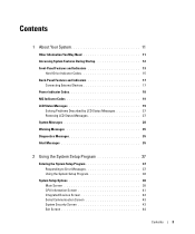
... Startup 12 Front-Panel Features and Indicators 13 Hard-Drive Indicator Codes 15 Back-Panel Features and Indicators 17 Connecting External Devices 17 Power Indicator Codes 18 NIC Indicator Codes 19 LCD Status Messages 19 Solving Problems Described by LCD Status ...Messages 27 Removing LCD Status Messages 27 System Messages 28 Warning Messages 35 Diagnostics Messages 35 Alert Messages 35 2 Using the System Setup Program 37 Entering the System Setup Program 37 Responding to Error...
... Startup 12 Front-Panel Features and Indicators 13 Hard-Drive Indicator Codes 15 Back-Panel Features and Indicators 17 Connecting External Devices 17 Power Indicator Codes 18 NIC Indicator Codes 19 LCD Status Messages 19 Solving Problems Described by LCD Status ...Messages 27 Removing LCD Status Messages 27 System Messages 28 Warning Messages 35 Diagnostics Messages 35 Alert Messages 35 2 Using the System Setup Program 37 Entering the System Setup Program 37 Responding to Error...
Hardware Owner's Manual (PDF)
Page 14
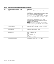
... (continued) Item Indicator, Button, or Connector Icon 4 LCD panel 5 USB connectors (2) Description Provides system ID, status information, and system error messages. NOTE: If the system is connected to AC power and an error has been detected, the LCD lights amber regardless of the system can cause the LCD to flash blue to... optional slimline IDE or DVD drive. 14 About Your System The LCD lights amber when the system needs attention, and the LCD panel displays an error code followed by descriptive text. Table 1-2. The LCD lights during normal system operation.
... (continued) Item Indicator, Button, or Connector Icon 4 LCD panel 5 USB connectors (2) Description Provides system ID, status information, and system error messages. NOTE: If the system is connected to AC power and an error has been detected, the LCD lights amber regardless of the system can cause the LCD to flash blue to... optional slimline IDE or DVD drive. 14 About Your System The LCD lights amber when the system needs attention, and the LCD panel displays an error code followed by descriptive text. Table 1-2. The LCD lights during normal system operation.
Hardware Owner's Manual (PDF)
Page 19
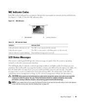
... or when the system needs attention. See Figure 1-5. Figure 1-5. NOTE: If your Product Information Guide for at least five seconds until an error code appears on page 147. The LCD scrolls a message that can occur and the probable cause for each message. The LCD messages refer to ...indicate an error condition. The LCD lights blue to indicate a normal operating condition, and lights amber to events recorded in the System Event Log (SEL). Table...
... or when the system needs attention. See Figure 1-5. Figure 1-5. NOTE: If your Product Information Guide for at least five seconds until an error code appears on page 147. The LCD scrolls a message that can occur and the probable cause for each message. The LCD messages refer to ...indicate an error condition. The LCD lights blue to indicate a normal operating condition, and lights amber to events recorded in the System Event Log (SEL). Table...
Hardware Owner's Manual (PDF)
Page 20
See "Using the System • The system is off and active POST errors are displayed. Cooling Problems" on page 118. disabled to prevent damage to connector. Battery" on page 119. page 74, and "Troubleshooting System Cooling Problems" on ... to the components. Check control panel LCD for information defined by the user in the System Setup under the following conditions: program. LCD Status Messages Code Text N/A SYSTEM NAME E1000 E1114 FAILSAFE, Call Support Temp Ambient E1116 Temp Memory E12nn xx PwrGd E1210 CMOS Batt E1211 ROMB Batt E1229 CPU # VCORE...
See "Using the System • The system is off and active POST errors are displayed. Cooling Problems" on page 118. disabled to prevent damage to connector. Battery" on page 119. page 74, and "Troubleshooting System Cooling Problems" on ... to the components. Check control panel LCD for information defined by the user in the System Setup under the following conditions: program. LCD Status Messages Code Text N/A SYSTEM NAME E1000 E1114 FAILSAFE, Call Support Temp Ambient E1116 Temp Memory E12nn xx PwrGd E1210 CMOS Batt E1211 ROMB Batt E1229 CPU # VCORE...
Hardware Owner's Manual (PDF)
Page 21
Ensure that the microprocessor heat sinks are in an Microprocessors" on support.dell.com for information about these utilities. The system BIOS has reported a See "Getting Help" on page 147. See your system's Getting ... described in the Microprocessor Technical Specifications outlined in your system's Information Update Tech Sheet located on page 128. processor initialization error. About Your System 21 LCD Status Messages (continued) Code E1410 E1414 E1418 E141C E141F E1420 E1421 Text CPU # IERR CPU # Thermtrip CPU # Presence CPU Mismatch CPU Protocol...
Ensure that the microprocessor heat sinks are in an Microprocessors" on support.dell.com for information about these utilities. The system BIOS has reported a See "Getting Help" on page 147. See your system's Getting ... described in the Microprocessor Technical Specifications outlined in your system's Information Update Tech Sheet located on page 128. processor initialization error. About Your System 21 LCD Status Messages (continued) Code E1410 E1414 E1418 E141C E141F E1420 E1421 Text CPU # IERR CPU # Thermtrip CPU # Presence CPU Mismatch CPU Protocol...

Hardware Owner's Manual (PDF)
Page 22
LCD Status Messages (continued) Code E1422 E1610 E1614 E1618 E161C E1620 E1624 E1710 Text Causes Corrective Actions CPU Machine Chk The system BIOS has reported a See "Getting Help" on page ... available from the specified power supply; If problem persists, see "Troubleshooting Power Supplies" on page 118. Table 1-6. specified power Supplies" on page 118. machine check error. supply fails, the system will go down. supply is no See "Troubleshooting Power longer redundant. PS # Input Range Power source for the specified power supply...
LCD Status Messages (continued) Code E1422 E1610 E1614 E1618 E161C E1620 E1624 E1710 Text Causes Corrective Actions CPU Machine Chk The system BIOS has reported a See "Getting Help" on page ... available from the specified power supply; If problem persists, see "Troubleshooting Power Supplies" on page 118. Table 1-6. specified power Supplies" on page 118. machine check error. supply fails, the system will go down. supply is no See "Troubleshooting Power longer redundant. PS # Input Range Power source for the specified power supply...

Hardware Owner's Manual (PDF)
Page 23
... ##, device ##, Expansion Cards" on page 127. LCD Status Messages (continued) Code E1711 E1712 E1714 E171F Text Causes Corrective Actions PCI PERR B## D## F## PCI PERR Slot # The system BIOS has reported a PCI parity error on page 124. PCI SERR B## D## F## PCI SERR Slot # The system...and reseat the PCI expansion cards. PCIE Fatal Err B## D## F## PCIE Fatal Err Slot # The system BIOS has reported a PCIe fatal error on page 147. that resides in the specified slot. Table 1-6. If the problem that resides in PCI configuration persists, see "Troubleshooting Expansion Cards...
... ##, device ##, Expansion Cards" on page 127. LCD Status Messages (continued) Code E1711 E1712 E1714 E171F Text Causes Corrective Actions PCI PERR B## D## F## PCI PERR Slot # The system BIOS has reported a PCI parity error on page 124. PCI SERR B## D## F## PCI SERR Slot # The system...and reseat the PCI expansion cards. PCIE Fatal Err B## D## F## PCIE Fatal Err Slot # The system BIOS has reported a PCIe fatal error on page 147. that resides in the specified slot. Table 1-6. If the problem that resides in PCI configuration persists, see "Troubleshooting Expansion Cards...
Hardware Owner's Manual (PDF)
Page 24
... Information only. See "Expansion-Card Riser Boards" on page 120. See "Installing Memory Modules" on page 147. 24 About Your System Error detected during memory configuration. Reseat the cable. If problem persists, replace cable. Install memory. See "Getting Help" on page 90. LCD Status... Messages (continued) Code E1811 E1812 E1913 E1A11 E1A12 E1A14 E1A15 E2010 E2011 E2012 E2013 E2014 E2015 Text Causes Corrective Actions HDD ## Rbld Abrt The specified hard...
... Information only. See "Expansion-Card Riser Boards" on page 120. See "Installing Memory Modules" on page 147. 24 About Your System Error detected during memory configuration. Reseat the cable. If problem persists, replace cable. Install memory. See "Getting Help" on page 90. LCD Status... Messages (continued) Code E1811 E1812 E1913 E1A11 E1A12 E1A14 E1A15 E2010 E2011 E2012 E2013 E2014 E2015 Text Causes Corrective Actions HDD ## Rbld Abrt The specified hard...
Hardware Owner's Manual (PDF)
Page 25
... test failure. messages. Memory Population Incorrect memory configuration. About Your System 25 Table 1-6. LCD Status Messages (continued) Code E2016 E2017 E2018 E2019 E201A E201B E201C E201D E201E E201F E2020 E2021 E2022 E2110 Text Causes Corrective Actions Int Controller Interrupt...Help" on page 120. DRAC Config Dell remote access controller Check screen for specific error messages. If problem persists, see "Getting Help" on page 147. See "Getting Help" on page 120. Prog Timer Programmable interval timer error. See "Troubleshooting System Memory" on page...
... test failure. messages. Memory Population Incorrect memory configuration. About Your System 25 Table 1-6. LCD Status Messages (continued) Code E2016 E2017 E2018 E2019 E201A E201B E201C E201D E201E E201F E2020 E2021 E2022 E2110 Text Causes Corrective Actions Int Controller Interrupt...Help" on page 120. DRAC Config Dell remote access controller Check screen for specific error messages. If problem persists, see "Getting Help" on page 147. See "Getting Help" on page 120. Prog Timer Programmable interval timer error. See "Troubleshooting System Memory" on page...

Hardware Owner's Manual (PDF)
Page 26
...on page 120. The fourth message displays as the standard overflow message. 26 About Your System Fatal NB Mem CRC One of three error events. the Southbound side has failed. Check the SEL for details on the A maximum of the connections in the See "Troubleshooting System...in the Fully Buffered DIMM (FBD) memory subsystem link on page 120. Intrusion System cover has been removed. LCD Status Messages (continued) Code E2111 E2112 E2113 E2118 E2119 I1910 I1911 Text Causes Corrective Actions SBE Log Disable Crd # DIMM ## The system BIOS has disabled See "...
...on page 120. The fourth message displays as the standard overflow message. 26 About Your System Fatal NB Mem CRC One of three error events. the Southbound side has failed. Check the SEL for details on the A maximum of the connections in the See "Troubleshooting System...in the Fully Buffered DIMM (FBD) memory subsystem link on page 120. Intrusion System cover has been removed. LCD Status Messages (continued) Code E2111 E2112 E2113 E2118 E2119 I1910 I1911 Text Causes Corrective Actions SBE Log Disable Crd # DIMM ## The system BIOS has disabled See "...
Hardware Owner's Manual (PDF)
Page 27
... the message from the electrical outlet; Table 1-6. W1228 ROMB Batt < 24hr Warns predictively that maps to determine the problem if multiple related errors occur. See "RAID battery has less than 24 hours of messages indicating multiple voltage faults, you might be able to the same display ... following conditions: • The sensor returns to a normal state but you know that is a failing power supply. For example, if the code E1418 CPU_1_Presence appears, you will remove fault messages, and return the status indicators and LCD colors to the normal state. In contrast, you must...
... the message from the electrical outlet; Table 1-6. W1228 ROMB Batt < 24hr Warns predictively that maps to determine the problem if multiple related errors occur. See "RAID battery has less than 24 hours of messages indicating multiple voltage faults, you might be able to the same display ... following conditions: • The sensor returns to a normal state but you know that is a failing power supply. For example, if the code E1418 CPU_1_Presence appears, you will remove fault messages, and return the status indicators and LCD colors to the normal state. In contrast, you must...
Hardware Owner's Manual (PDF)
Page 34
... the system. See the RAID controller documentation for processor 0 Micro code update failed. microprocessor combination. Utility partition not available The key was pressed...DIMMs. DIMMs should be populated sequentially starting in slots 1, 2, 5, and 6, etc.). Warning: Embedded RAID error. Populate 2, 4, or 8 DIMMs sequentially beginning with your system. See the RAID controller documentation for example...See "Getting Help" on the boot hard drive. Update the BIOS firmware. Dell recommends a population of an abbreviation or acronym used in this table, see the...
... the system. See the RAID controller documentation for processor 0 Micro code update failed. microprocessor combination. Utility partition not available The key was pressed...DIMMs. DIMMs should be populated sequentially starting in slots 1, 2, 5, and 6, etc.). Warning: Embedded RAID error. Populate 2, 4, or 8 DIMMs sequentially beginning with your system. See the RAID controller documentation for example...See "Getting Help" on the boot hard drive. Update the BIOS firmware. Dell recommends a population of an abbreviation or acronym used in this table, see the...
Hardware Owner's Manual (PDF)
Page 119
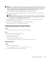
...properly. See "Replacing a Power Supply" on page 119. See "Power Indicator Codes" on page 18. 4 Check the indicators to overheat. Troubleshooting System Cooling Problems Problem • Systems management software issues a fan-related error message. See "Troubleshooting a Fan" on page 64. Operating the system for..."Removing a Power Supply" on page 63. 3 Ensure that the power supply is amber. • Systems management software issues a fan-related error message. • Front panel LCD indicates a problem with only one power supply at a time in a system that is in the redundant mode...
...properly. See "Replacing a Power Supply" on page 119. See "Power Indicator Codes" on page 18. 4 Check the indicators to overheat. Troubleshooting System Cooling Problems Problem • Systems management software issues a fan-related error message. See "Troubleshooting a Fan" on page 64. Operating the system for..."Removing a Power Supply" on page 63. 3 Ensure that the power supply is amber. • Systems management software issues a fan-related error message. • Front panel LCD indicates a problem with only one power supply at a time in a system that is in the redundant mode...


