
Information Update
Page 9
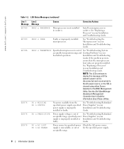
... range. See "Activating the Optional Integrated RAID Controller" in your Installation and Troubleshooting Guide. VOLT PG n System power supply is out of acceptable voltage range; faulty system board. Information Update 7 TEMP AMBIENT TEMP BMC Ambient system temperature... is out of three error messages can display sequentially on the events. See "Troubleshooting Redundant Power Supplies" in your Installation and Troubleshooting Guide. Replace the RAID battery. See "System Battery" in your Installation and Troubleshooting ...
... range. See "Activating the Optional Integrated RAID Controller" in your Installation and Troubleshooting Guide. VOLT PG n System power supply is out of acceptable voltage range; faulty system board. Information Update 7 TEMP AMBIENT TEMP BMC Ambient system temperature... is out of three error messages can display sequentially on the events. See "Troubleshooting Redundant Power Supplies" in your Installation and Troubleshooting Guide. Replace the RAID battery. See "System Battery" in your Installation and Troubleshooting ...
Information Update
Page 10
... Installation and Troubleshooting faulty. If the problem persists, ensure that the microprocessor heat sinks are properly installed. specified power supply is cleared using either Server Assistant or the BMC Management Utility. www.dell.com | support.dell.com Table 1-2. Install a microprocessor in your Installation and Troubleshooting Guide. See "Troubleshooting the Microprocessors" in socket n. See the...
... Installation and Troubleshooting faulty. If the problem persists, ensure that the microprocessor heat sinks are properly installed. specified power supply is cleared using either Server Assistant or the BMC Management Utility. www.dell.com | support.dell.com Table 1-2. Install a microprocessor in your Installation and Troubleshooting Guide. See "Troubleshooting the Microprocessors" in socket n. See the...

Information Update
Page 12
www.dell.com | support.dell.com Installing the Cable-Management Arm Although the cable-management arm can be installed on either side of the system rack, it on the left side of the system). Installing the cable-management arm on the right side (when facing the back of the rack will require you install it is recommended that you to disengage the cablemanagement arm to access the power supplies for removal or replacement. 10 Information Update
www.dell.com | support.dell.com Installing the Cable-Management Arm Although the cable-management arm can be installed on either side of the system rack, it on the left side of the system). Installing the cable-management arm on the right side (when facing the back of the rack will require you install it is recommended that you to disengage the cablemanagement arm to access the power supplies for removal or replacement. 10 Information Update

Information Update
Page 50
www.dell.com | support.dell.com 表 1-2 LCD 1 行目の 2 原因 対応処置 E0876 PS n MISSING PS n STATUS Troubleshooting Redundant Power Supplies E0876 PS n PREDICTIVE Troubleshooting Redundant Power Supplies E0876 PS n AC LOST PS n AC RANGE AC AC AC E0D76 BP DRIVE n 1x2 DRIVE FAIL n SCSI CONNECTOR RAID Troubleshooting SCSI Hard Drives」...
www.dell.com | support.dell.com 表 1-2 LCD 1 行目の 2 原因 対応処置 E0876 PS n MISSING PS n STATUS Troubleshooting Redundant Power Supplies E0876 PS n PREDICTIVE Troubleshooting Redundant Power Supplies E0876 PS n AC LOST PS n AC RANGE AC AC AC E0D76 BP DRIVE n 1x2 DRIVE FAIL n SCSI CONNECTOR RAID Troubleshooting SCSI Hard Drives」...

Rack- to-Tower Conversion Guide
Page 8
... begin installing your system in the rack, carefully read "Safety Instructions," found earlier in this kit are similar. NOTE: If your Dell system is provided to components in a rack cabinet. Use only the rack kit for your System Information document for trained service technicians ...in any system/component when servicing other systems/components in your Dell system. www.dell.com | support.dell.com Y1001bk0.book Page 6 Thursday, July 8, 2004 4:32 PM • Do not overload the power supply branch circuit that provides power to install the next system. The total rack load should...
... begin installing your system in the rack, carefully read "Safety Instructions," found earlier in this kit are similar. NOTE: If your Dell system is provided to components in a rack cabinet. Use only the rack kit for your System Information document for trained service technicians ...in any system/component when servicing other systems/components in your Dell system. www.dell.com | support.dell.com Y1001bk0.book Page 6 Thursday, July 8, 2004 4:32 PM • Do not overload the power supply branch circuit that provides power to install the next system. The total rack load should...

Rack Installation Guide
Page 8
... system that is required for each system installed in a rack. 1-6 Rack Installation Guide CAUTION: Safety Instructions (continued) • Do not overload the AC supply branch circuit that provides power to others. The RapidRails™ rack kit can be installed in either center-mount or flush-mount configuration, for your system. This guide...
... system that is required for each system installed in a rack. 1-6 Rack Installation Guide CAUTION: Safety Instructions (continued) • Do not overload the AC supply branch circuit that provides power to others. The RapidRails™ rack kit can be installed in either center-mount or flush-mount configuration, for your system. This guide...

Rack Installation Guide
Page 20
Installing the Cable-Management Arm system status indicator cable plug wire covers in open position system status indicator 7 Connect the power cords to provide strain relief for the power cables. 1-18 Rack Installation Guide Figure 1-9. NOTE: Use the strain-relief loops (if available) on the back of the power supplies to their receptacles on the back panel (see Figure 1-10).
Installing the Cable-Management Arm system status indicator cable plug wire covers in open position system status indicator 7 Connect the power cords to provide strain relief for the power cables. 1-18 Rack Installation Guide Figure 1-9. NOTE: Use the strain-relief loops (if available) on the back of the power supplies to their receptacles on the back panel (see Figure 1-10).


