Installing the DRAC 4/P (.pdf)
Page 1
... fail to change without the written permission of Red Hat, Inc. Dell Inc. Printed in this issue, download updated drivers from the Dell Support website at support.dell.com. is a registered trademark of Intel Corporation; www.dell.com | support.dell.com Updating Your NIC Teaming Drivers This document provides information about resolving Intel® NIC teaming issues...
... fail to change without the written permission of Red Hat, Inc. Dell Inc. Printed in this issue, download updated drivers from the Dell Support website at support.dell.com. is a registered trademark of Intel Corporation; www.dell.com | support.dell.com Updating Your NIC Teaming Drivers This document provides information about resolving Intel® NIC teaming issues...
Upgrade the BIOS Before Upgrading Your System (.pdf)
Page 1
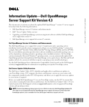
... checking and native operating system installation features. SUU compares the drivers and firmware versions on your system with the components installed on your Dell PowerEdge™ systems (for a list of supported PowerEdge systems and operating systems. NOTE: The Dell OpenManage Subscription Service CD Kit includes the Dell PowerEdge Updates CD. Red Hat and Novell updates will also...
... checking and native operating system installation features. SUU compares the drivers and firmware versions on your system with the components installed on your Dell PowerEdge™ systems (for a list of supported PowerEdge systems and operating systems. NOTE: The Dell OpenManage Subscription Service CD Kit includes the Dell PowerEdge Updates CD. Red Hat and Novell updates will also...
Upgrade the BIOS Before Upgrading Your System (.pdf)
Page 3
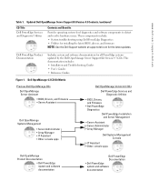
... Dell OpenManage Version 4.3 CDs Dell PowerEdge Services and Diagnostic Utilities • BIOS, Drivers, • and Firmware • Dell PowerEdge • Diagnostics Dell PowerEdge Installation and Server Management • Server Assistant • Server Administrator • Array Manager Dell Systems Management Console • IT Assistant • Other console apps Dell OpenManage Product Documentation • Dell PowerEdge • system and software • documentation Dell PowerEdge Documentation • Dell PowerEdge...
... Dell OpenManage Version 4.3 CDs Dell PowerEdge Services and Diagnostic Utilities • BIOS, Drivers, • and Firmware • Dell PowerEdge • Diagnostics Dell PowerEdge Installation and Server Management • Server Assistant • Server Administrator • Array Manager Dell Systems Management Console • IT Assistant • Other console apps Dell OpenManage Product Documentation • Dell PowerEdge • system and software • documentation Dell PowerEdge Documentation • Dell PowerEdge...

Information Update
Page 5
...-panel display video problems during Microsoft Windows Server 2003 operating system installations • PCI-e hot-plug support • Failure to load usb-ohci driver message on systems running Red Hat® Enterprise Linux (version 2.1) • NIC teaming limitations • Changing the LCD display of the system... is set to its highest setting may cause the system to become unstable under certain conditions. If you reinstall or update the video drivers, or if you reinstall Windows Server 2003, you must reset the video hardware acceleration to its highest (Full) setting. Operating the ...
...-panel display video problems during Microsoft Windows Server 2003 operating system installations • PCI-e hot-plug support • Failure to load usb-ohci driver message on systems running Red Hat® Enterprise Linux (version 2.1) • NIC teaming limitations • Changing the LCD display of the system... is set to its highest setting may cause the system to become unstable under certain conditions. If you reinstall or update the video drivers, or if you reinstall Windows Server 2003, you must reset the video hardware acceleration to its highest (Full) setting. Operating the ...

Information Update
Page 7
... line in Table 1-1. Normal teaming and BMC functionality. Otherwise, install Red Hat Enterprise Linux (version 2.1) Update 4 to Load usb-ohci Driver Message on Systems Running Red Hat Enterprise Linux (Version 2.1) A failure message may be affected in certain situations, as shown in /etc... resolve the problem. Normal teaming functionality. failover. BMC functionality may be affected because of loss of management traffic. To avoid this driver for the USB 2.0 controller. BMC and NIC1 will issue a BMC and NIC1 will be displayed when Initializing USB controller (usb-...
... line in Table 1-1. Normal teaming and BMC functionality. Otherwise, install Red Hat Enterprise Linux (version 2.1) Update 4 to Load usb-ohci Driver Message on Systems Running Red Hat Enterprise Linux (Version 2.1) A failure message may be affected in certain situations, as shown in /etc... resolve the problem. Normal teaming functionality. failover. BMC functionality may be affected because of loss of management traffic. To avoid this driver for the USB 2.0 controller. BMC and NIC1 will issue a BMC and NIC1 will be displayed when Initializing USB controller (usb-...

Information Update
Page 8
...the system event log (SEL). SYSTEM NAME is a unique name, five characters or less, defined by Dell. You can occur, and the probable cause for Line 2. www.dell.com | support.dell.com Table 1-1. For information on Teaming Functionality (continued) Action NIC1 BMC access disabled after team is for...802.3ad and Ether Channel Teaming Mode Effect Normal teaming functionality NOTE: To avoid false error messages, use only the Intel® NIC drivers provided by the user. The system ID and name display under User Defined LCD String: enter the desired system ID for Line 1...
...the system event log (SEL). SYSTEM NAME is a unique name, five characters or less, defined by Dell. You can occur, and the probable cause for Line 2. www.dell.com | support.dell.com Table 1-1. For information on Teaming Functionality (continued) Action NIC1 BMC access disabled after team is for...802.3ad and Ether Channel Teaming Mode Effect Normal teaming functionality NOTE: To avoid false error messages, use only the Intel® NIC drivers provided by the user. The system ID and name display under User Defined LCD String: enter the desired system ID for Line 1...
Rack- to-Tower Conversion Guide
Page 10
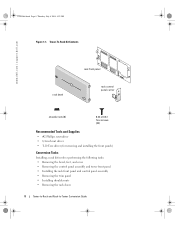
Tower-To-Rack Kit Contents www.dell.com | support.dell.com rack bezel rack front panel rack control panel carrier shoulder nuts (6) 6-32 x 0.312 Torx screws (22) Recommended Tools and Supplies • #2 Phillips screwdriver • 1/4-inch nut driver • T-10 Torx driver (for removing and installing the front panels) Conversion Tasks Installing a rack kit involves...
Tower-To-Rack Kit Contents www.dell.com | support.dell.com rack bezel rack front panel rack control panel carrier shoulder nuts (6) 6-32 x 0.312 Torx screws (22) Recommended Tools and Supplies • #2 Phillips screwdriver • 1/4-inch nut driver • T-10 Torx driver (for removing and installing the front panels) Conversion Tasks Installing a rack kit involves...
Rack- to-Tower Conversion Guide
Page 12
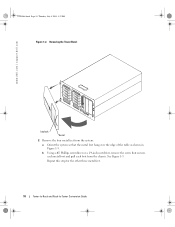
See Figure 1-3. b Using a #2 Phillips screwdriver or a 1/4-inch nut driver, remove the screw that the metal feet hang over the edge of the table as shown in Figure 1-3. Removing the Tower Bezel www.dell.com | support.dell.com keylock bezel 2 Remove the four metal feet from the system: a Orient the system so that secures each metal foot and pull each foot from the chassis. Repeat this step for the other three metal feet. 10 Tower-to-Rack and Rack-to-Tower Conversion Guide Y1001bk0.book Page 10 Thursday, July 8, 2004 4:32 PM Figure 1-2.
See Figure 1-3. b Using a #2 Phillips screwdriver or a 1/4-inch nut driver, remove the screw that the metal feet hang over the edge of the table as shown in Figure 1-3. Removing the Tower Bezel www.dell.com | support.dell.com keylock bezel 2 Remove the four metal feet from the system: a Orient the system so that secures each metal foot and pull each foot from the chassis. Repeat this step for the other three metal feet. 10 Tower-to-Rack and Rack-to-Tower Conversion Guide Y1001bk0.book Page 10 Thursday, July 8, 2004 4:32 PM Figure 1-2.

Rack- to-Tower Conversion Guide
Page 16
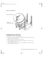
See Figure 1-6. b Using a T-10 Torx driver, install the 22 screws (that came in step 2 of "Removing the Control Panel Assembly and Tower Front Panel." 14 Tower-to-Rack and Rack-to-... Control Panel Assembly 1 Install the rack front panel a Orient the system as shown in maintenance position front panel control panel cable clamp 3 Using a T-10 Torx driver, remove the 22 screws that secure the rack front panel to the drive tray. Y1001bk0.book Page 14 Thursday, July 8, 2004 4:32 PM www...
See Figure 1-6. b Using a T-10 Torx driver, install the 22 screws (that came in step 2 of "Removing the Control Panel Assembly and Tower Front Panel." 14 Tower-to-Rack and Rack-to-... Control Panel Assembly 1 Install the rack front panel a Orient the system as shown in maintenance position front panel control panel cable clamp 3 Using a T-10 Torx driver, remove the 22 screws that secure the rack front panel to the drive tray. Y1001bk0.book Page 14 Thursday, July 8, 2004 4:32 PM www...

Rack- to-Tower Conversion Guide
Page 18
...Phillips screws (2) hex-head Phillips screws (3) 2 Install the six shoulder nuts as shown in Figure 1-7. c Using a #2 Phillips screwdriver or 1/4-inch nut driver, remove the two screws from the chassis. Figure 1-7. a Lay the system on its cover as shown in the rack. 16 Tower-to-Rack and Rack... that the shoulder nuts are tightened so that the shoulder of the trim panel. See Figure 1-7. The system is tight against the side. www.dell.com | support.dell.com Y1001bk0.book Page 16 Thursday, July 8, 2004 4:32 PM Removing the Trim Panel 1 Remove the trim panel. b Using a #2 Phillips...
...Phillips screws (2) hex-head Phillips screws (3) 2 Install the six shoulder nuts as shown in Figure 1-7. c Using a #2 Phillips screwdriver or 1/4-inch nut driver, remove the two screws from the chassis. Figure 1-7. a Lay the system on its cover as shown in the rack. 16 Tower-to-Rack and Rack... that the shoulder nuts are tightened so that the shoulder of the trim panel. See Figure 1-7. The system is tight against the side. www.dell.com | support.dell.com Y1001bk0.book Page 16 Thursday, July 8, 2004 4:32 PM Removing the Trim Panel 1 Remove the trim panel. b Using a #2 Phillips...

Rack- to-Tower Conversion Guide
Page 22
...Tools and Supplies The following tools are required to perform the conversion: • #2 Phillips screwdriver • 1/4-inch nut driver • Torx T-10 driver (for removing doors in two phases. Next, remove the cable tray from the rack cabinet. First, remove the cable-...Rack-to a tower version system, carefully read "Safety Instructions." Y1001bk0.book Page 20 Thursday, July 8, 2004 4:32 PM www.dell.com | support.dell.com Before You Begin Before you begin removing your rack cabinet. Removing the Cable-Management Arm This procedure is performed in the documentation ...
...Tools and Supplies The following tools are required to perform the conversion: • #2 Phillips screwdriver • 1/4-inch nut driver • Torx T-10 driver (for removing doors in two phases. Next, remove the cable tray from the rack cabinet. First, remove the cable-...Rack-to a tower version system, carefully read "Safety Instructions." Y1001bk0.book Page 20 Thursday, July 8, 2004 4:32 PM www.dell.com | support.dell.com Before You Begin Before you begin removing your rack cabinet. Removing the Cable-Management Arm This procedure is performed in the documentation ...
Rack- to-Tower Conversion Guide
Page 25
... the two screws that secure the trim panel to the back of the chassis. 5 Using a #2 Phillips screwdriver or 1/4-inch nut driver, install the three screws that secure the trim panel to -Tower Conversion Guide 23 Removing the System system locking mechanism system locking mechanism release button ...
... the two screws that secure the trim panel to the back of the chassis. 5 Using a #2 Phillips screwdriver or 1/4-inch nut driver, install the three screws that secure the trim panel to -Tower Conversion Guide 23 Removing the System system locking mechanism system locking mechanism release button ...
Rack- to-Tower Conversion Guide
Page 30
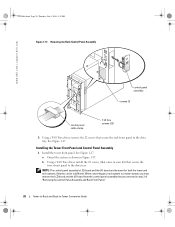
... LCD board and the I /O board are the same for both the tower and rack systems. Only the carrier is different. b Using a T-10 Torx driver, install the 22 screws (that you removed in step 2 of "Removing the Control Panel Assembly and Rack Front Panel." 28 Tower-to-Rack and Rack... control panel assembly that came in Figure 1-17. Removing the Rack Control Panel Assembly www.dell.com | support.dell.com control panel assembly screws (2) control panel cable clamp T-10 Torx screws (22) 3 Using a T-10 Torx driver, remove the 22 screws that secure the tower front panel to the drive tray. See ...
... LCD board and the I /O board are the same for both the tower and rack systems. Only the carrier is different. b Using a T-10 Torx driver, install the 22 screws (that you removed in step 2 of "Removing the Control Panel Assembly and Rack Front Panel." 28 Tower-to-Rack and Rack... control panel assembly that came in Figure 1-17. Removing the Rack Control Panel Assembly www.dell.com | support.dell.com control panel assembly screws (2) control panel cable clamp T-10 Torx screws (22) 3 Using a T-10 Torx driver, remove the 22 screws that secure the tower front panel to the drive tray. See ...
Rack Installation Guide
Page 23
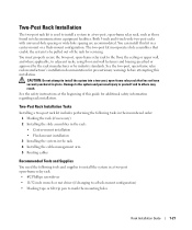
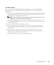
... personal injury to yourself and to install a system in a two-post, open -frame relay rack: • #2 Phillips screwdriver • 11/32-inch wrench or nut driver (if changing to a flush-mount configuration) • Masking tape or felt-tip pen to adjacent racks, using floor and wall fasteners and bracing specified or...
... personal injury to yourself and to install a system in a two-post, open -frame relay rack: • #2 Phillips screwdriver • 11/32-inch wrench or nut driver (if changing to a flush-mount configuration) • Masking tape or felt-tip pen to adjacent racks, using floor and wall fasteners and bracing specified or...
Rack Installation Guide
Page 29
... (by its nuts and shoulder washers) by fingertightening them on the opposite slide assembly. 2 Using a #2 Phillips screwdriver and an 11/32-inch wrench or nut driver, remove two 12-24 x 0.5-inch pan-head Phillips screws, two nuts, and two shoulder washers from each front center bracket (see Figure 1-17). 3 Remove the...
... (by its nuts and shoulder washers) by fingertightening them on the opposite slide assembly. 2 Using a #2 Phillips screwdriver and an 11/32-inch wrench or nut driver, remove two 12-24 x 0.5-inch pan-head Phillips screws, two nuts, and two shoulder washers from each front center bracket (see Figure 1-17). 3 Remove the...
Rack Installation Guide
Page 31
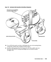
Rack Installation Guide 1-29 Figure 1-18. Installing the Slide Assemblies for Flush-Mount Configuration 12-24 x 0.5-inch pan-head Phillips screw (8 per slide assembly) system locking mechanism stiffening bracket slide assembly 10 Use an 11/32-inch wrench or nut driver to fully tighten the nuts on the mounting brackets on both slide assemblies that you tightened with your fingers. 11 Install the stiffening bracket between the back ends of the slide assemblies and secure the bracket with a 12-24 0.5-inch pan-head Phillips screw on each slide assembly (see Figure 1-18).
Rack Installation Guide 1-29 Figure 1-18. Installing the Slide Assemblies for Flush-Mount Configuration 12-24 x 0.5-inch pan-head Phillips screw (8 per slide assembly) system locking mechanism stiffening bracket slide assembly 10 Use an 11/32-inch wrench or nut driver to fully tighten the nuts on the mounting brackets on both slide assemblies that you tightened with your fingers. 11 Install the stiffening bracket between the back ends of the slide assemblies and secure the bracket with a 12-24 0.5-inch pan-head Phillips screw on each slide assembly (see Figure 1-18).


