Installing the DRAC 4/P (.pdf)
Page 1
...be used in this document to refer to change without the written permission of Dell Inc. All rights reserved. Other trademarks and trade names may cause a kernel panic when Dell Online diagnostic memory tests are running 802.3ad Dynamic Link Aggregation on some switches. To correct this... issue, download updated drivers from the Dell Support website at support.dell.com. July 2004 To correct this issue, download ...
...be used in this document to refer to change without the written permission of Dell Inc. All rights reserved. Other trademarks and trade names may cause a kernel panic when Dell Online diagnostic memory tests are running 802.3ad Dynamic Link Aggregation on some switches. To correct this... issue, download updated drivers from the Dell Support website at support.dell.com. July 2004 To correct this issue, download ...

Processor Upgrade Installation Guide (.pdf)
Page 1
... components. 1 Turn off the system, including any of the system (if present). See Figure 1. 4 Remove the memory cooling shroud (if present). 5 Remove the memory module fans at the back of the system (if present). 6 Remove the fan bracket at the back of the ...components inside the computer, and protecting against electrostatic discharge. This document provides instructions for complete information about safety precautions, working inside the system. www.dell.com | support.dell...
... components. 1 Turn off the system, including any of the system (if present). See Figure 1. 4 Remove the memory cooling shroud (if present). 5 Remove the memory module fans at the back of the system (if present). 6 Remove the fan bracket at the back of the ...components inside the computer, and protecting against electrostatic discharge. This document provides instructions for complete information about safety precautions, working inside the system. www.dell.com | support.dell...
Processor Upgrade Installation Guide (.pdf)
Page 2
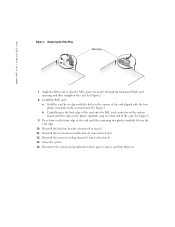
... standoffs snap over the card edge. 10 Reinstall the back fan bracket (if removed in step 6). 11 Reinstall the two memory module fans (if removed in step 5). 12 Reinstall the memory cooling shroud (if removed in the corners of the card aligned with the holes in step 4). 13 Close the system. 14... Filler Plug filler plug 7 Angle the RAC card so that end of the card onto the RAC card connector on the system board. www.dell.com | support.dell.com Figure 1. See Figure 2. 8 Install the RAC card: a Hold the card by its edges with the four plastic standoffs on the system board, until...
... standoffs snap over the card edge. 10 Reinstall the back fan bracket (if removed in step 6). 11 Reinstall the two memory module fans (if removed in step 5). 12 Reinstall the memory cooling shroud (if removed in the corners of the card aligned with the holes in step 4). 13 Close the system. 14... Filler Plug filler plug 7 Angle the RAC card so that end of the card onto the RAC card connector on the system board. www.dell.com | support.dell.com Figure 1. See Figure 2. 8 Install the RAC card: a Hold the card by its edges with the four plastic standoffs on the system board, until...
Information Update
Page 11
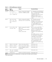
... or system board. Reinstall the expansion-card cage. See "Getting Help" in your Installation and Troubleshooting Guide. EB107 MEMORY SPARED Memory spare bank enabled. If the problem persists, see "Getting Help" in your Installation and Troubleshooting Guide. Information only....an abbreviation or acronym used in this table, see "Troubleshooting Expansion Cards" in your Installation and Troubleshooting Guide. EB107 MEMORY MIRRORED Memory mirroring enabled. IB110 SBE LOG DISABLED LOGGING DISABLED Information only. LCD Status Messages (continued) Line 1 Line 2 Message ...
... or system board. Reinstall the expansion-card cage. See "Getting Help" in your Installation and Troubleshooting Guide. EB107 MEMORY SPARED Memory spare bank enabled. If the problem persists, see "Getting Help" in your Installation and Troubleshooting Guide. Information only....an abbreviation or acronym used in this table, see "Troubleshooting Expansion Cards" in your Installation and Troubleshooting Guide. EB107 MEMORY MIRRORED Memory mirroring enabled. IB110 SBE LOG DISABLED LOGGING DISABLED Information only. LCD Status Messages (continued) Line 1 Line 2 Message ...
Information Update
Page 51
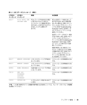
Card Cage EB107 MEMORY MIRRORED です。 EB107 MEMORY SPARED です。 EFFF2 ROMB PRESENCE 内蔵 RAID です。 IB110 SBE LOG DISABLED LOGGING DISABLED IS000 INTRUSION います。 &#...
Card Cage EB107 MEMORY MIRRORED です。 EB107 MEMORY SPARED です。 EFFF2 ROMB PRESENCE 内蔵 RAID です。 IB110 SBE LOG DISABLED LOGGING DISABLED IS000 INTRUSION います。 &#...
Information Update
Page 60
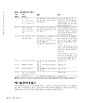
www.dell.com | support.dell.com 표 1-2. LCD Line 1 메시지 E0D76 EB107 EB107 Line 2 메시지 BP DRIVE n 1x2 DRIVE FAIL n SCSI CONNECTOR PROC BUS ...PROTOCOL ERR PCIE FATAL ERR CHIPSET ERR 원인 조치 RAID SCSI "RAID RAID 설치된 PCI-e PCI-e EB107 EB107 EFFF2 IB110 MEMORY MIRRORED MEMORY SPARED ROMB PRESENCE SBE LOG DISABLED LOGGING DISABLED 통합된 RAID IS000 INTRUSION 58
www.dell.com | support.dell.com 표 1-2. LCD Line 1 메시지 E0D76 EB107 EB107 Line 2 메시지 BP DRIVE n 1x2 DRIVE FAIL n SCSI CONNECTOR PROC BUS ...PROTOCOL ERR PCIE FATAL ERR CHIPSET ERR 원인 조치 RAID SCSI "RAID RAID 설치된 PCI-e PCI-e EB107 EB107 EFFF2 IB110 MEMORY MIRRORED MEMORY SPARED ROMB PRESENCE SBE LOG DISABLED LOGGING DISABLED 통합된 RAID IS000 INTRUSION 58
Processor Upgrade Installation Guide
Page 5
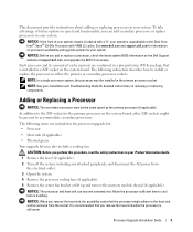
...add or replace a processor, check the latest system BIOS information on processor availability and upgrade options for information on the Dell Support website at support.dell.com, and upgrade the BIOS if necessary. The following items are contained in your system. In addition to the ... NOTE: See your Installation and Troubleshooting Guide for the primary processor on removing or replacing components. Each processor and its associated cache memory are included in a ZIF socket on the system board. NOTICE: The processor and heat sink can add secondary processors or replace ...
...add or replace a processor, check the latest system BIOS information on processor availability and upgrade options for information on the Dell Support website at support.dell.com, and upgrade the BIOS if necessary. The following items are contained in your system. In addition to the ... NOTE: See your Installation and Troubleshooting Guide for the primary processor on removing or replacing components. Each processor and its associated cache memory are included in a ZIF socket on the system board. NOTICE: The processor and heat sink can add secondary processors or replace ...
Processor Upgrade Installation Guide
Page 9
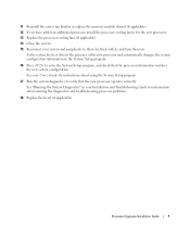
... Setup program. 16 Press to their electrical outlets, and turn them on. Processor Upgrade Installation Guide 7 11 Reinstall the center fan bracket or replace the memory module shroud (if applicable). 12 If you have added an additional processor, install the processor cooling fan(s) for the new processor. 13 Replace the processor...
... Setup program. 16 Press to their electrical outlets, and turn them on. Processor Upgrade Installation Guide 7 11 Reinstall the center fan bracket or replace the memory module shroud (if applicable). 12 If you have added an additional processor, install the processor cooling fan(s) for the new processor. 13 Replace the processor...
Activating the Integrated RAID Controller
Page 5
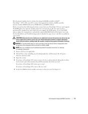
...and disconnect the AC power from SCSI to step 5. If you have a PowerEdge 2800 system, go to RAID. If a memory module connector is installed in your system. If you have a PowerEdge 1850 system, remove the riser card insulator by lifting the two blue rivets at...if applicable). 2 Turn off of riser card that your Product Information Guide for detailed instructions on Dell™ PowerEdge™ 1850, 2800, and 2850 systems. Your upgrade kit includes a RAID controller memory module, RAID hardware key, RAID battery, and RAID software. NOTE: See your Installation and ...
...and disconnect the AC power from SCSI to step 5. If you have a PowerEdge 2800 system, go to RAID. If a memory module connector is installed in your system. If you have a PowerEdge 1850 system, remove the riser card insulator by lifting the two blue rivets at...if applicable). 2 Turn off of riser card that your Product Information Guide for detailed instructions on Dell™ PowerEdge™ 1850, 2800, and 2850 systems. Your upgrade kit includes a RAID controller memory module, RAID hardware key, RAID battery, and RAID software. NOTE: See your Installation and ...
Activating the Integrated RAID Controller
Page 6
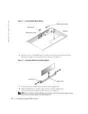
... memory modules such as those used for system memory. Installing the RAID Controller Memory Module ejectors (2) alignment key 7 Locate the memory module that is included with the upgrade kit. 8 Align the RAID memory ...module's edge connector with the alignment key, and insert the memory module into the connector. Use the memory module supplied in the RAID upgrade kit. 1-4 Activating the Integrated RAID Controller See Figure 1-2. www.dell.com | support.dell...
... memory modules such as those used for system memory. Installing the RAID Controller Memory Module ejectors (2) alignment key 7 Locate the memory module that is included with the upgrade kit. 8 Align the RAID memory ...module's edge connector with the alignment key, and insert the memory module into the connector. Use the memory module supplied in the RAID upgrade kit. 1-4 Activating the Integrated RAID Controller See Figure 1-2. www.dell.com | support.dell...
Activating the Integrated RAID Controller
Page 7
...instructions. 16 Connect the RAID battery to step 13. 12 If you have a PowerEdge 2800 system, remove the memory cooling shroud by lifting the release latch and sliding the shroud forward. If you have a PowerEdge 2800 system: a Position the RAID battery over the RAID battery holder with the latches ... for more information. c Install the RAID battery into the RAID battery holder. See Figure 1-3. 14 If you have a PowerEdge 2800 or 2850 system, replace or lower the memory cooling shroud. 15 If you are replacing a RAID battery, see the "Battery Disposal" section in the riser, which is...
...instructions. 16 Connect the RAID battery to step 13. 12 If you have a PowerEdge 2800 system, remove the memory cooling shroud by lifting the release latch and sliding the shroud forward. If you have a PowerEdge 2800 system: a Position the RAID battery over the RAID battery holder with the latches ... for more information. c Install the RAID battery into the RAID battery holder. See Figure 1-3. 14 If you have a PowerEdge 2800 or 2850 system, replace or lower the memory cooling shroud. 15 If you are replacing a RAID battery, see the "Battery Disposal" section in the riser, which is...


