
User Guide
Page 4
... 2.5.6 PCI Express 2.0 x16 slot 2-21 2.6 Jumper...2-22 2.7 Connectors 2-23 2.7.1 Rear panel connectors 2-23 2.7.2 Audio I/O connections 2-26 2.7.3 Internal connectors 2-28 2.8 Starting up for the first time 2-35 2.9 Turning off the computer 2-35 Chapter 3: BIOS setup 3.1 Knowing BIOS 3-1 3.2 Updating BIOS 3-1 3.2.1 ASUS Update utility 3-2 3.2.2 ASUS EZ Flash 2 utility 3-4 3.2.3 ASUS CrashFree BIOS 3 utility 3-5 3.2.4 ASUS BIOS Updater 3-6 3.3 BIOS setup program 3-9 3.3.1 BIOS menu...
... 2.5.6 PCI Express 2.0 x16 slot 2-21 2.6 Jumper...2-22 2.7 Connectors 2-23 2.7.1 Rear panel connectors 2-23 2.7.2 Audio I/O connections 2-26 2.7.3 Internal connectors 2-28 2.8 Starting up for the first time 2-35 2.9 Turning off the computer 2-35 Chapter 3: BIOS setup 3.1 Knowing BIOS 3-1 3.2 Updating BIOS 3-1 3.2.1 ASUS Update utility 3-2 3.2.2 ASUS EZ Flash 2 utility 3-4 3.2.3 ASUS CrashFree BIOS 3 utility 3-5 3.2.4 ASUS BIOS Updater 3-6 3.3 BIOS setup program 3-9 3.3.1 BIOS menu...

User Guide
Page 8
... on it by yourself. If you are using, contact your dealer immediately. • To avoid short circuits, keep paper clips, screws, and staples away from connectors, slots, sockets and circuitry. • Avoid dust, humidity, and temperature extremes. Contact a qualified service technician or your retailer. Safety information Electrical safety • To prevent...
... on it by yourself. If you are using, contact your dealer immediately. • To avoid short circuits, keep paper clips, screws, and staples away from connectors, slots, sockets and circuitry. • Avoid dust, humidity, and temperature extremes. Contact a qualified service technician or your retailer. Safety information Electrical safety • To prevent...

User Guide
Page 9
...and connectors on ASUS hardware and software products. Refer to change system settings through the BIOS Setup menus. About this guide is organized This guide contains the following sources for additional information and for product and software updates. 1. ASUS websites The ASUS website... provides updated information on the motherboard. • Chapter 3: BIOS setup This chapter tells how to the ASUS contact information. 2. Optional documentation Your product package may have ...
...and connectors on ASUS hardware and software products. Refer to change system settings through the BIOS Setup menus. About this guide is organized This guide contains the following sources for additional information and for product and software updates. 1. ASUS websites The ASUS website... provides updated information on the motherboard. • Chapter 3: BIOS setup This chapter tells how to the ASUS contact information. 2. Optional documentation Your product package may have ...

User Guide
Page 13
xiii P7H55-M PRO specifications summary Back Panel I/O Ports 1 x PS/2 Keyboard port (purple) 1 x HDMI Output 1 x DVI-D Output 1 x D-Sub Output 1 x Optical S/PDIF Out 1 x RJ45 port 6 x USB 2.0/1.1 ports 8-channel Audio I/O Internal I/O Connectors 3 x USB connectors support additional 6 USB ports 1 x IDE connector 6 x SATA 3.0Gb/s connectors 1 x CPU Fan connector 1 x 4-pin Chassis Fan connector 1 x Power Fan connector 1 x COM connector 1 x Front panel audio connector 1 x S/PDIF Out Header 1 x Clear CMOS jumper...
xiii P7H55-M PRO specifications summary Back Panel I/O Ports 1 x PS/2 Keyboard port (purple) 1 x HDMI Output 1 x DVI-D Output 1 x D-Sub Output 1 x Optical S/PDIF Out 1 x RJ45 port 6 x USB 2.0/1.1 ports 8-channel Audio I/O Internal I/O Connectors 3 x USB connectors support additional 6 USB ports 1 x IDE connector 6 x SATA 3.0Gb/s connectors 1 x CPU Fan connector 1 x 4-pin Chassis Fan connector 1 x Power Fan connector 1 x COM connector 1 x Front panel audio connector 1 x S/PDIF Out Header 1 x Clear CMOS jumper...

User Guide
Page 22
2.2 Motherboard overview 2.2.1 Motherboard layout Chapter 2 Refer to 2.7 Connectors for more information about rear panel connectors and internal connectors. 2-2 Chapter 2: Hardware information
2.2 Motherboard overview 2.2.1 Motherboard layout Chapter 2 Refer to 2.7 Connectors for more information about rear panel connectors and internal connectors. 2-2 Chapter 2: Hardware information

User Guide
Page 26
... plate is on the bottom‑left corner of the socket, and then fit the socket alignment keys into the socket to prevent bending the connectors on the socket and damaging the CPU! Lift the load lever in only one correct orientation. 3.
... plate is on the bottom‑left corner of the socket, and then fit the socket alignment keys into the socket to prevent bending the connectors on the socket and damaging the CPU! Lift the load lever in only one correct orientation. 3.

User Guide
Page 28
The LGA1156 socket is closest to the CPU fan connector. 2-8 Chapter 2: Hardware information Place the heatsink on top of the installed CPU, ensuring that the CPU fan cable is incompatible with the LGA775 and LGA1366 ...
The LGA1156 socket is closest to the CPU fan connector. 2-8 Chapter 2: Hardware information Place the heatsink on top of the installed CPU, ensuring that the CPU fan cable is incompatible with the LGA775 and LGA1366 ...

User Guide
Page 29
3. Pull up two fasteners at a time in a B diagonal sequence to the connector on the motherboard. 2. Carefully remove the heatsink and fan assembly from the motherboard. ASUS P7H55-M PRO 2-9 Connect the CPU fan cable to disengage the heatsink and fan assembly from the... motherboard. Hardware monitoring errors can occur if you fail to connect the CPU fan connector! Rotate each fastener counterclockwise. 3. Disconnect...
3. Pull up two fasteners at a time in a B diagonal sequence to the connector on the motherboard. 2. Carefully remove the heatsink and fan assembly from the motherboard. ASUS P7H55-M PRO 2-9 Connect the CPU fan cable to disengage the heatsink and fan assembly from the... motherboard. Hardware monitoring errors can occur if you fail to connect the CPU fan connector! Rotate each fastener counterclockwise. 3. Disconnect...
User Guide
Page 39
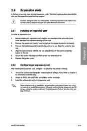
...install an expansion card 1. Remove the bracket opposite the slot that came with it by adjusting the software settings. 1. Align the card connector with the screw you may cause you intend to the chassis with the slot and press firmly until the card is already installed in .... 2. Refer to unplug the power cord before adding or removing expansion cards. Chapter 2 2.5 Expansion slots In the future, you removed earlier. 6. ASUS P7H55-M PRO 2-19 Failure to do not need to the table on the system and change the necessary BIOS settings, if any. Replace the system cover...
...install an expansion card 1. Remove the bracket opposite the slot that came with it by adjusting the software settings. 1. Align the card connector with the screw you may cause you intend to the chassis with the slot and press firmly until the card is already installed in .... 2. Refer to unplug the power cord before adding or removing expansion cards. Chapter 2 2.5 Expansion slots In the future, you removed earlier. 6. ASUS P7H55-M PRO 2-19 Failure to do not need to the table on the system and change the necessary BIOS settings, if any. Replace the system cover...

User Guide
Page 43
PS/2 keyboard port (purple) 2. Optical S/PDIF Out port 3. USB 2.0 ports 5 and 6 6. ASUS P7H55-M PRO 2-23 DVI-D out port 8. Audio I/O ports** *and **: Refer to the tables on the next page for LAN port and audio port definitions. ***: Refer to the notes and troubleshooting on monitor overscan / underscan problem on the next pages. HDMI out port*** 7. VGA out port 4. USB 2.0 ports 3 and 4 9. 2.7 Connectors 2.7.1 Rear panel connectors Chapter 2 Rear panel connectors 1. LAN (RJ-45) port 5. USB 2.0 ports 1 and 2 10.
PS/2 keyboard port (purple) 2. Optical S/PDIF Out port 3. USB 2.0 ports 5 and 6 6. ASUS P7H55-M PRO 2-23 DVI-D out port 8. Audio I/O ports** *and **: Refer to the tables on the next page for LAN port and audio port definitions. ***: Refer to the notes and troubleshooting on monitor overscan / underscan problem on the next pages. HDMI out port*** 7. VGA out port 4. USB 2.0 ports 3 and 4 9. 2.7 Connectors 2.7.1 Rear panel connectors Chapter 2 Rear panel connectors 1. LAN (RJ-45) port 5. USB 2.0 ports 1 and 2 10.

User Guide
Page 48
... the IDE cable. • Use the 80-conductor IDE cable for the Ultra DMA 133/100 signal cable. There are three connectors on the Ultra DMA cable connector. If any device jumper is for Ultra DMA 133/100 IDE devices. Chapter 2 Single device Two devices Drive jumper setting Cable-... of the following modes to match the covered hole on each Ultra DMA 133/100 signal cable: blue, black, and gray. IDE connector (40-1 pin PRI_IDE) The onboard IDE connector is set as "Cable-Select", ensure that all other device jumpers have the same setting. 2-28 Chapter 2: Hardware information
... the IDE cable. • Use the 80-conductor IDE cable for the Ultra DMA 133/100 signal cable. There are three connectors on the Ultra DMA cable connector. If any device jumper is for Ultra DMA 133/100 IDE devices. Chapter 2 Single device Two devices Drive jumper setting Cable-... of the following modes to match the covered hole on each Ultra DMA 133/100 signal cable: blue, black, and gray. IDE connector (40-1 pin PRI_IDE) The onboard IDE connector is set as "Cable-Select", ensure that all other device jumpers have the same setting. 2-28 Chapter 2: Hardware information

User Guide
Page 49
Chapter 2 You must install Windows® XP Service Pack 2 or later versions before using Serial ATA hard disk drives. ASUS P7H55-M PRO 2-29 Intel® H55 Serial ATA connectors (7-pin SATA 1-6) These connectors connect to Serial ATA hard disk drives and optical disc drives via Serial ATA signal cables. 2.
Chapter 2 You must install Windows® XP Service Pack 2 or later versions before using Serial ATA hard disk drives. ASUS P7H55-M PRO 2-29 Intel® H55 Serial ATA connectors (7-pin SATA 1-6) These connectors connect to Serial ATA hard disk drives and optical disc drives via Serial ATA signal cables. 2.

User Guide
Page 50
... cable to any of these connectors, then install the module to a slot opening at the back of the system chassis. The USB module is for USB 2.0 ports. USB910; These USB connectors comply with USB 2.0 specification that supports up to the USB connectors. Connect the serial port module... cable to this connector, then install the module to a slot opening at the back of the system chassis....
... cable to any of these connectors, then install the module to a slot opening at the back of the system chassis. The USB module is for USB 2.0 ports. USB910; These USB connectors comply with USB 2.0 specification that supports up to the USB connectors. Connect the serial port module... cable to this connector, then install the module to a slot opening at the back of the system chassis....

User Guide
Page 51
5. Do not forget to connect the fan cables to the fan connectors on the fan connectors! • The CPU_FAN connector supports the CPU fan of the connector. Insufficient air flow inside the system may damage the motherboard components. These are not jumpers! Chapter 2 ASUS P7H55-M PRO 2-31 Do not place jumper caps on the motherboard, ensuring that...
5. Do not forget to connect the fan cables to the fan connectors on the fan connectors! • The CPU_FAN connector supports the CPU fan of the connector. Insufficient air flow inside the system may damage the motherboard components. These are not jumpers! Chapter 2 ASUS P7H55-M PRO 2-31 Do not place jumper caps on the motherboard, ensuring that...

User Guide
Page 52
... We recommend that supports either HD Audio or legacy AC`97 audio standard. The S/PDIF module is set the item to this connector. Connect one end of the front panel audio I /O module that you connect a high-definition front panel audio module to this.... • If you want to connect a high-definition front panel audio module to this connector, then install the module to [HD Audio]. 2-32 Chapter 2: Hardware information Digital audio connector (4-1 pin SPDIF_OUT) This connector is for an additional Sony/Philips Digital Interface (S/PDIF) port(s). 6. if you want to ...
... We recommend that supports either HD Audio or legacy AC`97 audio standard. The S/PDIF module is set the item to this connector. Connect one end of the front panel audio I /O module that you connect a high-definition front panel audio module to this.... • If you want to connect a high-definition front panel audio module to this connector, then install the module to [HD Audio]. 2-32 Chapter 2: Hardware information Digital audio connector (4-1 pin SPDIF_OUT) This connector is for an additional Sony/Philips Digital Interface (S/PDIF) port(s). 6. if you want to ...

User Guide
Page 53
...-351HT Thermaltake TWV500W-AP Thermaltake PUREPower-600AP Zippy HP2-6500PE (G1) Zippy PSL6720P ASUS P7H55-M PRO 2-33 Find the proper orientation and push down firmly until the connectors completely fit. com/PowerSupplyCalculator/PSCalculator.aspx?SLanguage=en-us for ATX power supply plugs... minimum power of 350 W. • Do not forget to connect the 8-pin EATX12 V power plug; ATX power connectors (24-pin EATXPWR; 8-pin EATX12V) These connectors are designed to the Recommended Power Supply Wattage Calculator at http://support.asus. 8. The power supply plugs are for details.
...-351HT Thermaltake TWV500W-AP Thermaltake PUREPower-600AP Zippy HP2-6500PE (G1) Zippy PSL6720P ASUS P7H55-M PRO 2-33 Find the proper orientation and push down firmly until the connectors completely fit. com/PowerSupplyCalculator/PSCalculator.aspx?SLanguage=en-us for ATX power supply plugs... minimum power of 350 W. • Do not forget to connect the 8-pin EATX12 V power plug; ATX power connectors (24-pin EATXPWR; 8-pin EATX12V) These connectors are designed to the Recommended Power Supply Wattage Calculator at http://support.asus. 8. The power supply plugs are for details.

User Guide
Page 54
... for the chassis-mounted reset button for system reboot without turning off button (2-pin PWRSW) This connector is for the HDD Activity LED. Chapter 2 • System power LED (2-pin PLED) This 2-pin connector is for the system power LED. The speaker allows you turn on the BIOS settings. Connect ...Activity LED cable to the HDD. • System warning speaker (4-pin SPEAKER) This 4-pin connector is for the chassis-mounted system warning speaker. The IDE LED lights up when you to this connector. Pressing the power button turns the system on or puts the system in sleep or soft-...
... for the chassis-mounted reset button for system reboot without turning off button (2-pin PWRSW) This connector is for the HDD Activity LED. Chapter 2 • System power LED (2-pin PLED) This 2-pin connector is for the system power LED. The speaker allows you turn on the BIOS settings. Connect ...Activity LED cable to the HDD. • System warning speaker (4-pin SPEAKER) This 4-pin connector is for the chassis-mounted system warning speaker. The IDE LED lights up when you to this connector. Pressing the power button turns the system on or puts the system in sleep or soft-...

User Guide
Page 55
...down the key to a power outlet that all the connections, replace the system case cover. 2. Pressing the power switch for the first time 1. ASUS P7H55-M PRO 2-35 If your retailer for less than four seconds lets the system enter the soft-off mode, depending on the BIOS setting. After ...making all switches are running, the BIOS beeps (see anything within 30 seconds from orange to the power connector at the back of the BIOS setting. The system then runs the power-on the devices in Chapter 3. 2.9 Turning off the computer While...
...down the key to a power outlet that all the connections, replace the system case cover. 2. Pressing the power switch for the first time 1. ASUS P7H55-M PRO 2-35 If your retailer for less than four seconds lets the system enter the soft-off mode, depending on the BIOS setting. After ...making all switches are running, the BIOS beeps (see anything within 30 seconds from orange to the power connector at the back of the BIOS setting. The system then runs the power-on the devices in Chapter 3. 2.9 Turning off the computer While...

User Guide
Page 81
...Enables the J-Micron PATA controller. [Disabled] Disables the J-Micron PATA controller. Front Panel Type [HD Audio] [AC97] Set the front panel audio connector (AAFP) mode to HDMI out. LAN Boot ROM [Disabled] This item appears only when you to select the Serial Port1 base address. Set ... audio connector (AAFP) mode to high-definition SPDIF OUT Mode Setting [SPDIF] [SPDIF] Set the audio output to SPDIF out. [HDMI] Set to audio output to legacy AC'97. [HD Audio] audio. Configuration options: [Disabled] [3F8/IRQ4] [2F8/IRQ3] [3E8/IRQ4] [2E8/IRQ3] Chapter 3 ASUS P7H55-M PRO...
...Enables the J-Micron PATA controller. [Disabled] Disables the J-Micron PATA controller. Front Panel Type [HD Audio] [AC97] Set the front panel audio connector (AAFP) mode to HDMI out. LAN Boot ROM [Disabled] This item appears only when you to select the Serial Port1 base address. Set ... audio connector (AAFP) mode to high-definition SPDIF OUT Mode Setting [SPDIF] [SPDIF] Set the audio output to SPDIF out. [HDMI] Set to audio output to legacy AC'97. [HD Audio] audio. Configuration options: [Disabled] [3F8/IRQ4] [2F8/IRQ3] [3E8/IRQ4] [2E8/IRQ3] Chapter 3 ASUS P7H55-M PRO...

User Guide
Page 107
... Information button Exit button Minimize button Chapter 4 Information button ASUS P7H55-M PRO 4-11 Realtek HD Audio Manager for Windows® Vista™ Set default device button Minimize button Configuration option tabs Exit button Device advanced settings Connector settings Control settings window Analog and digital connector status B. The CODEC also includes the Realtek® proprietary...
... Information button Exit button Minimize button Chapter 4 Information button ASUS P7H55-M PRO 4-11 Realtek HD Audio Manager for Windows® Vista™ Set default device button Minimize button Configuration option tabs Exit button Device advanced settings Connector settings Control settings window Analog and digital connector status B. The CODEC also includes the Realtek® proprietary...


