Motherboard Installation Guide
Page 1
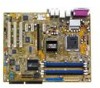
Motherboard P5RD1-V Deluxe
Motherboard P5RD1-V Deluxe
Motherboard Installation Guide
Page 3
Contents Notices vii Safety information viii About this guide ix Typography x P5RD1-V Deluxe specifications summary xi Chapter 1: Product introduction 1.1 Welcome 1-1 1.2 Package contents 1-1 1.3 Special features 1-2 1.3.1 Product highlights 1-2 1.3.2 ASUS Proactive feature 1-4 1.3.3 Innovative ASUS features 1-5 Chapter 2: Hardware information 2.1 Before you proceed 2-1 2.2 Motherboard overview 2-2 2.2.1 Placement direction 2-2 2.2.2 Screw holes 2-2 2.2.3 Motherboard layout 2-3 2.2.4 Layout Contents 2-4 2.3 Central Processing Unit (CPU 2-6 2.3.1 Installing the CPU 2-6 2.3.2 ...
Contents Notices vii Safety information viii About this guide ix Typography x P5RD1-V Deluxe specifications summary xi Chapter 1: Product introduction 1.1 Welcome 1-1 1.2 Package contents 1-1 1.3 Special features 1-2 1.3.1 Product highlights 1-2 1.3.2 ASUS Proactive feature 1-4 1.3.3 Innovative ASUS features 1-5 Chapter 2: Hardware information 2.1 Before you proceed 2-1 2.2 Motherboard overview 2-2 2.2.1 Placement direction 2-2 2.2.2 Screw holes 2-2 2.2.3 Motherboard layout 2-3 2.2.4 Layout Contents 2-4 2.3 Central Processing Unit (CPU 2-6 2.3.1 Installing the CPU 2-6 2.3.2 ...
Motherboard Installation Guide
Page 8
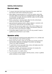
...are not sure about the voltage of the electrical outlet you add a device. • Before connecting or removing signal cables from the motherboard, ensure that came with the product, contact a qualified service technician or your dealer immediately. • To avoid short circuits, keep ... away from connectors, slots, sockets and circuitry. • Avoid dust, humidity, and temperature extremes. Operation safety • Before installing the motherboard and adding devices on a stable surface. • If you detect any area where it may become wet. • Place the product ...
...are not sure about the voltage of the electrical outlet you add a device. • Before connecting or removing signal cables from the motherboard, ensure that came with the product, contact a qualified service technician or your dealer immediately. • To avoid short circuits, keep ... away from connectors, slots, sockets and circuitry. • Avoid dust, humidity, and temperature extremes. Operation safety • Before installing the motherboard and adding devices on a stable surface. • If you detect any area where it may become wet. • Place the product ...

Motherboard Installation Guide
Page 9
... This chapter lists the hardware setup procedures that you need when installing and configuring the motherboard. ASUS websites The ASUS website provides updated information on ASUS hardware and software products. Optional documentation Your product package may have to the ASUS contact information. 2. How this guide This user guide contains the information you have been added...
... This chapter lists the hardware setup procedures that you need when installing and configuring the motherboard. ASUS websites The ASUS website provides updated information on ASUS hardware and software products. Optional documentation Your product package may have to the ASUS contact information. 2. How this guide This user guide contains the information you have been added...
Motherboard Installation Guide
Page 15
This chapter describes the motherboard features and the new technologies it supports. 1Product introduction
This chapter describes the motherboard features and the new technologies it supports. 1Product introduction

Motherboard Installation Guide
Page 17
... is damaged or missing, contact your retailer. Before you for the following items. Motherboard ASUS P5RD1-V Deluxe motherboard I /O shield NTSC-to-PAL adaptor A p p l i c a t i o n C D s ASUS motherboard support CD InterVideo® WinDVD® Suite InterVideo® Home Theater® D o c u m e n t a t i o n User guide If any of ASUS quality motherboards! ASUS P5RD1-V Deluxe 1-1 1.1 Welcome! The motherboard delivers a host of new features and latest technologies, making it , check the...
... is damaged or missing, contact your retailer. Before you for the following items. Motherboard ASUS P5RD1-V Deluxe motherboard I /O shield NTSC-to-PAL adaptor A p p l i c a t i o n C D s ASUS motherboard support CD InterVideo® WinDVD® Suite InterVideo® Home Theater® D o c u m e n t a t i o n User guide If any of ASUS quality motherboards! ASUS P5RD1-V Deluxe 1-1 1.1 Welcome! The motherboard delivers a host of new features and latest technologies, making it , check the...
Motherboard Installation Guide
Page 18
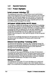
...CPU voltage and core frequency depending on installing and uninstalling the required drivers. 1-2 Chapter 1: Product introduction See 2-25 for details. The motherboard also supports the Intel® Hyper-Threading technology and is software compatible with 533/800 MHz front side bus (FSB), dual channel DDR ... The ATI Radeon® XPRESS 200 Northbridge integrates the Radeon® X300 GPU, an integrated graphics processing unit (GPU) for the motherboard. ATI Radeon® XPRESS 200/ULI M1573 chipset The ATI Radeon® XPRESS 200 Northbridge and the ULI M1573 Southbridge provide the ...
...CPU voltage and core frequency depending on installing and uninstalling the required drivers. 1-2 Chapter 1: Product introduction See 2-25 for details. The motherboard also supports the Intel® Hyper-Threading technology and is software compatible with 533/800 MHz front side bus (FSB), dual channel DDR ... The ATI Radeon® XPRESS 200 Northbridge integrates the Radeon® X300 GPU, an integrated graphics processing unit (GPU) for the motherboard. ATI Radeon® XPRESS 200/ULI M1573 chipset The ATI Radeon® XPRESS 200 Northbridge and the ULI M1573 Southbridge provide the ...
Motherboard Installation Guide
Page 19
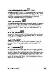
...M1573 Southbridge allows RAID 0, RAID 1, RAID 0+1, and JBOD configuration. See page 5-35 for details. Gigabit LAN The motherboard comes with the Marvell® Yukon™ 88E8001 Gigabit LAN controller to meet your computer to home theater decoders to ... motherboard supports the Serial ATA technology through simple, low-cost, high-bandwidth asynchronous (real-time) data interfacing between computers, peripherals, and consumer electronic devices such as camcorders, VCRs, printers,TVs, and digital cameras. The IEEE 1394a interface allows up to IEEE 1394a standards. ASUS P5RD1-V Deluxe...
...M1573 Southbridge allows RAID 0, RAID 1, RAID 0+1, and JBOD configuration. See page 5-35 for details. Gigabit LAN The motherboard comes with the Marvell® Yukon™ 88E8001 Gigabit LAN controller to meet your computer to home theater decoders to ... motherboard supports the Serial ATA technology through simple, low-cost, high-bandwidth asynchronous (real-time) data interfacing between computers, peripherals, and consumer electronic devices such as camcorders, VCRs, printers,TVs, and digital cameras. The IEEE 1394a interface allows up to IEEE 1394a standards. ASUS P5RD1-V Deluxe...
Motherboard Installation Guide
Page 21
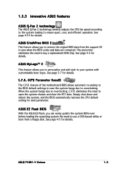
... eliminates the need to restore the original BIOS data from a floppy disk. ASUS P5RD1-V Deluxe 1-5 ASUS EZ Flash BIOS With the ASUS EZ Flash, you to buy a replacement ROM chip. 1.3.3 Innovative ASUS features ASUS Q-Fan 2 technology The ASUS Q-Fan 2 technology smartly adjusts the CPU fan speed according to the system ...loading to open the system chassis and clear the RTC data. ASUS MyLogo™ 2 This feature allows you to personalize and add style to overclocking. feature of the motherboard BIOS allows automatic re-setting to the BIOS default settings in case ...
... eliminates the need to restore the original BIOS data from a floppy disk. ASUS P5RD1-V Deluxe 1-5 ASUS EZ Flash BIOS With the ASUS EZ Flash, you to buy a replacement ROM chip. 1.3.3 Innovative ASUS features ASUS Q-Fan 2 technology The ASUS Q-Fan 2 technology smartly adjusts the CPU fan speed according to the system ...loading to open the system chassis and clear the RTC data. ASUS MyLogo™ 2 This feature allows you to personalize and add style to overclocking. feature of the motherboard BIOS allows automatic re-setting to the BIOS default settings in case ...

Motherboard Installation Guide
Page 23
It includes description of the jumpers and connectors on the motherboard. 2 Hardware information This chapter lists the hardware setup procedures that you have to perform when installing system components.
It includes description of the jumpers and connectors on the motherboard. 2 Hardware information This chapter lists the hardware setup procedures that you have to perform when installing system components.

Motherboard Installation Guide
Page 24
Chapter summary 2 2.1 Before you proceed 2-1 2.2 Motherboard overview 2-2 2.3 Central Processing Unit (CPU 2-6 2.4 System memory 2-13 2.5 Expansion slots 2-18 2.6 Jumpers 2-21 2.7 Connectors 2-24 ASUS P5RD1-V Deluxe
Chapter summary 2 2.1 Before you proceed 2-1 2.2 Motherboard overview 2-2 2.3 Central Processing Unit (CPU 2-6 2.4 System memory 2-13 2.5 Expansion slots 2-18 2.6 Jumpers 2-21 2.7 Connectors 2-24 ASUS P5RD1-V Deluxe
Motherboard Installation Guide
Page 25
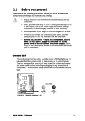
... in any motherboard component. P5RD1-V ® SB_PWR ON Standby Power P5RD1-V DELUXE Onboard LED OFF Powered Off ASUS P5RD1-V Deluxe 2-1 The illustration below shows the location of the following precautions before you install motherboard components or change any motherboard settings. •... in soft-off or the p o w e r c o r d i s d e t a c h e d f r o m t h e p o w e r s u p p l y . Onboard LED The motherboard comes with the component. • Before you install or remove any component, ensure that the system is switched off mode. 2.1 Before you proceed Take note...
... in any motherboard component. P5RD1-V ® SB_PWR ON Standby Power P5RD1-V DELUXE Onboard LED OFF Powered Off ASUS P5RD1-V Deluxe 2-1 The illustration below shows the location of the following precautions before you install motherboard components or change any motherboard settings. •... in soft-off or the p o w e r c o r d i s d e t a c h e d f r o m t h e p o w e r s u p p l y . Onboard LED The motherboard comes with the component. • Before you install or remove any component, ensure that the system is switched off mode. 2.1 Before you proceed Take note...
Motherboard Installation Guide
Page 26
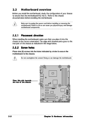
... part of the chassis P5RD1-V ® 2-2 Chapter 2: Hardware information Place this side towards the rear of the chassis as indicated in the image below. 2.2.2 Screw holes Place nine (9) screws into the chassis in the correct orientation. Make sure to the chassis documentation before installing or removing the motherboard. Doing so can cause...
... part of the chassis P5RD1-V ® 2-2 Chapter 2: Hardware information Place this side towards the rear of the chassis as indicated in the image below. 2.2.2 Screw holes Place nine (9) screws into the chassis in the correct orientation. Make sure to the chassis documentation before installing or removing the motherboard. Doing so can cause...
Motherboard Installation Guide
Page 30
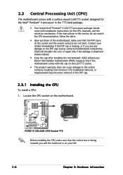
... The product warranty does not cover damage to the PnP cap/socket contacts/motherboard components. ASUS will process Return Merchandise Authorization (RMA) requests only if the motherboard comes with installation instructions for the Intel® Pentium® 4 processor ...the cap after installing the motherboard. Contact your left. 2-6 Chapter 2: Hardware information 2.3 Central Processing Unit (CPU) The motherboard comes with a surface mount LGA775 socket designed for the CPU, heatsink, and the retention mechanism. P5RD1-V ® P5RD1-V DELUXE CPU Socket 775 Before installing ...
... The product warranty does not cover damage to the PnP cap/socket contacts/motherboard components. ASUS will process Return Merchandise Authorization (RMA) requests only if the motherboard comes with installation instructions for the Intel® Pentium® 4 processor ...the cap after installing the motherboard. Contact your left. 2-6 Chapter 2: Hardware information 2.3 Central Processing Unit (CPU) The motherboard comes with a surface mount LGA775 socket designed for the CPU, heatsink, and the retention mechanism. P5RD1-V ® P5RD1-V DELUXE CPU Socket 775 Before installing ...
Motherboard Installation Guide
Page 32
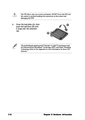
B The motherboard supports Intel® Pentium® 4 LGA775 processors with the Enhanced Intel SpeedStep® Technology (EIST) and Hyper-Threading Technology. Close the load plate (A), then A push the load lever (B) until it snaps into the socket to the Appendix for more information on the socket and damaging the CPU! 6. The CPU fits in only one correct orientation. Refer to prevent bending the connectors on these CPU features. 2-8 Chapter 2: Hardware information DO NOT force the CPU into the retention tab.
B The motherboard supports Intel® Pentium® 4 LGA775 processors with the Enhanced Intel SpeedStep® Technology (EIST) and Hyper-Threading Technology. Close the load plate (A), then A push the load lever (B) until it snaps into the socket to the Appendix for more information on the socket and damaging the CPU! 6. The CPU fits in only one correct orientation. Refer to prevent bending the connectors on these CPU features. 2-8 Chapter 2: Hardware information DO NOT force the CPU into the retention tab.
Motherboard Installation Guide
Page 33
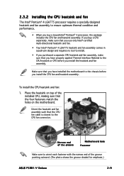
Make sure that you have installed the motherboard to the chassis before you install the heatsink and fan assembly. Place the heatsink on top of the groove pointing outward. (The photo shows the groove shaded for emphasis.) ASUS P5RD1-V Deluxe 2-9 2.3.2 Installing the CPU heatsink and fan The Intel® Pentium®...processor, the package includes the CPU fan and heatsink assembly. To install the CPU heatsink and fan: 1. Narrow end of the groove Motherboard hole Fastener Make sure to orient each fastener with the narrow end of the installed CPU, making sure that the CPU fan cable ...
Make sure that you have installed the motherboard to the chassis before you install the heatsink and fan assembly. Place the heatsink on top of the groove pointing outward. (The photo shows the groove shaded for emphasis.) ASUS P5RD1-V Deluxe 2-9 2.3.2 Installing the CPU heatsink and fan The Intel® Pentium®...processor, the package includes the CPU fan and heatsink assembly. To install the CPU heatsink and fan: 1. Narrow end of the groove Motherboard hole Fastener Make sure to orient each fastener with the narrow end of the installed CPU, making sure that the CPU fan cable ...
Motherboard Installation Guide
Page 34
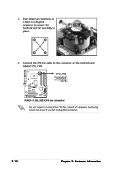
Push down two fasteners at a time in a diagonal sequence to connect the CPU fan connector! P5RD1-V ® CPU_FAN CPU FAN PWM CPU FAN IN CPU FAN PWR GND P5RD1-V DELUXE CPU fan connector Do not forget to secure the B heatsink and fan assembly in A place. Connect the CPU fan cable to plug this connector. 2-10 Chapter 2: Hardware information A B A B B A 3. Hardware monitoring errors can occur if you fail to the connector on the motherboard labeled CPU_FAN. 2.
Push down two fasteners at a time in a diagonal sequence to connect the CPU fan connector! P5RD1-V ® CPU_FAN CPU FAN PWM CPU FAN IN CPU FAN PWR GND P5RD1-V DELUXE CPU fan connector Do not forget to secure the B heatsink and fan assembly in A place. Connect the CPU fan cable to plug this connector. 2-10 Chapter 2: Hardware information A B A B B A 3. Hardware monitoring errors can occur if you fail to the connector on the motherboard labeled CPU_FAN. 2.

Motherboard Installation Guide
Page 35
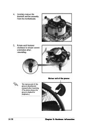
Disconnect the CPU fan cable from the A motherboard. Pull up two fasteners at a time in a diagonal sequence to disengage the heatsink B and fan assembly from the connector on the motherboard. 2. Rotate each fastener counterclockwise. 3. A B A B B A ASUS P5RD1-V Deluxe 2-11 2.3.3 Uninstalling the CPU heatsink and fan To uninstall the CPU heatsink and fan: 1.
Disconnect the CPU fan cable from the A motherboard. Pull up two fasteners at a time in a diagonal sequence to disengage the heatsink B and fan assembly from the connector on the motherboard. 2. Rotate each fastener counterclockwise. 3. A B A B B A ASUS P5RD1-V Deluxe 2-11 2.3.3 Uninstalling the CPU heatsink and fan To uninstall the CPU heatsink and fan: 1.
Motherboard Installation Guide
Page 36
The narrow end of the groove should point outward after resetting. (The photo shows the groove shaded for emphasis.) Narrow end of the groove 2-12 Chapter 2: Hardware information Carefully remove the heatsink and fan assembly from the motherboard. 5. Rotate each fastener clockwise to ensure correct orientation when reinstalling. 4.
The narrow end of the groove should point outward after resetting. (The photo shows the groove shaded for emphasis.) Narrow end of the groove 2-12 Chapter 2: Hardware information Carefully remove the heatsink and fan assembly from the motherboard. 5. Rotate each fastener clockwise to ensure correct orientation when reinstalling. 4.
Motherboard Installation Guide
Page 37
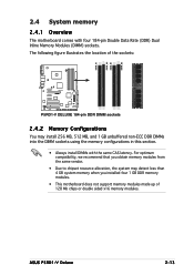
ASUS P5RD1-V Deluxe 2-13 The following figure illustrates the location of the sockets: P5RD1-V ® P5RD1-V DELUXE 184-pin DDR DIMM sockets 2.4.2 Memory Configurations You may detect less than 4 GB system memory when you obtain memory modules from the same vendor...(DDR) Dual Inline Memory Modules (DIMM) sockets. For optimum compatibility, we recommend that you installed four 1 GB DDR memory modules. • This motherboard does not support memory modules made up of 128 Mb chips or double sided x16 memory modules. DIMM_A1 DIMM_A2 DIMM_B1 DIMM_B2 2.4 System memory 2.4.1 Overview The...
ASUS P5RD1-V Deluxe 2-13 The following figure illustrates the location of the sockets: P5RD1-V ® P5RD1-V DELUXE 184-pin DDR DIMM sockets 2.4.2 Memory Configurations You may detect less than 4 GB system memory when you obtain memory modules from the same vendor...(DDR) Dual Inline Memory Modules (DIMM) sockets. For optimum compatibility, we recommend that you installed four 1 GB DDR memory modules. • This motherboard does not support memory modules made up of 128 Mb chips or double sided x16 memory modules. DIMM_A1 DIMM_A2 DIMM_B1 DIMM_B2 2.4 System memory 2.4.1 Overview The...


