
Motherboard Installation Guide
Page 17
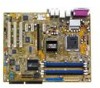
...making it , check the items in your package with the list below. 1.2 Package contents Check your retailer. Before you for the following items. Motherboard ASUS P5RD1-V Deluxe motherboard I/O modules 1 x TV-out/capture-in module 1 x Serial port module 1 x IEEE 1394a (1 port) module 1 x USB 2.0 (2... 1 x 4-in the long line of the above items is damaged or missing, contact your motherboard package for buying an ASUS® P5RD1-V Deluxe motherboard! 1.1 Welcome! Thank you start installing the motherboard, and hardware devices on it another standout in -1 Floppy/IDE signal...
...making it , check the items in your package with the list below. 1.2 Package contents Check your retailer. Before you for the following items. Motherboard ASUS P5RD1-V Deluxe motherboard I/O modules 1 x TV-out/capture-in module 1 x Serial port module 1 x IEEE 1394a (1 port) module 1 x USB 2.0 (2... 1 x 4-in the long line of the above items is damaged or missing, contact your motherboard package for buying an ASUS® P5RD1-V Deluxe motherboard! 1.1 Welcome! Thank you start installing the motherboard, and hardware devices on it another standout in -1 Floppy/IDE signal...
Motherboard Installation Guide
Page 19
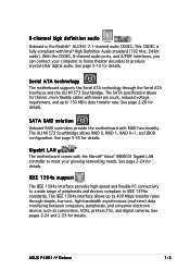
... such as camcorders, VCRs, printers,TVs, and digital cameras. The ULI M1573 Southbridge allows RAID 0, RAID 1, RAID 0+1, and JBOD configuration. See page 2-24 for details. ASUS P5RD1-V Deluxe 1-3 With the CODEC, 8-channel audio ports, and S/PDIF interfaces, you can connect your growing networking needs. See page 2-28 for details. IEEE 1394a support The...
... such as camcorders, VCRs, printers,TVs, and digital cameras. The ULI M1573 Southbridge allows RAID 0, RAID 1, RAID 0+1, and JBOD configuration. See page 2-24 for details. ASUS P5RD1-V Deluxe 1-3 With the CODEC, 8-channel audio ports, and S/PDIF interfaces, you can connect your growing networking needs. See page 2-28 for details. IEEE 1394a support The...
Motherboard Installation Guide
Page 21
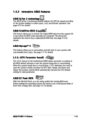
... 5-7 for details. C.P.R. (CPU Parameter Recall) The C.P.R. eliminates the need to your system with customizable boot logos. See page 4-5 for details. ASUS P5RD1-V Deluxe 1-5 ASUS MyLogo™ 2 This feature allows you to open the system chassis and clear the RTC data. Simply shut down and reboot the system, and the... allows automatic re-setting to the BIOS default settings in case when the BIOS codes and data are corrupted. ASUS EZ Flash BIOS With the ASUS EZ Flash, you can easily update the system BIOS even before loading the operating system. When the system hangs...
... 5-7 for details. C.P.R. (CPU Parameter Recall) The C.P.R. eliminates the need to your system with customizable boot logos. See page 4-5 for details. ASUS P5RD1-V Deluxe 1-5 ASUS MyLogo™ 2 This feature allows you to open the system chassis and clear the RTC data. Simply shut down and reboot the system, and the... allows automatic re-setting to the BIOS default settings in case when the BIOS codes and data are corrupted. ASUS EZ Flash BIOS With the ASUS EZ Flash, you can easily update the system BIOS even before loading the operating system. When the system hangs...

Motherboard Installation Guide
Page 24
Chapter summary 2 2.1 Before you proceed 2-1 2.2 Motherboard overview 2-2 2.3 Central Processing Unit (CPU 2-6 2.4 System memory 2-13 2.5 Expansion slots 2-18 2.6 Jumpers 2-21 2.7 Connectors 2-24 ASUS P5RD1-V Deluxe
Chapter summary 2 2.1 Before you proceed 2-1 2.2 Motherboard overview 2-2 2.3 Central Processing Unit (CPU 2-6 2.4 System memory 2-13 2.5 Expansion slots 2-18 2.6 Jumpers 2-21 2.7 Connectors 2-24 ASUS P5RD1-V Deluxe
Motherboard Installation Guide
Page 25
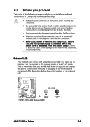
... LED The motherboard comes with the component. • Before you uninstall any component, place it on a grounded antistatic pad or in soft-off or the p o w e r c o r d i s d e t a c h e d f r o m t h e p o w e r s u p p l y . P5RD1-V ® SB_PWR ON Standby Power P5RD1-V DELUXE Onboard LED OFF Powered Off ASUS P5RD1-V Deluxe 2-1
... LED The motherboard comes with the component. • Before you uninstall any component, place it on a grounded antistatic pad or in soft-off or the p o w e r c o r d i s d e t a c h e d f r o m t h e p o w e r s u p p l y . P5RD1-V ® SB_PWR ON Standby Power P5RD1-V DELUXE Onboard LED OFF Powered Off ASUS P5RD1-V Deluxe 2-1

Motherboard Installation Guide
Page 29
...) - Reset switch (Blue 2-pin RESET) Page 2-26 2-27 2-28 2-29 2-29 2-29 2-30 2-30 2-31 2-31 2-32 2-32 2-33 2-33 2-34 2-34 2-35 2-35 2-36 ASUS P5RD1-V Deluxe 2-5 Chassis fan connector (3-pin CHA_FAN1) 6. Serial port connector (10-1 pin COM1) 8. Front panel audio connector (10-1 pin AAFP) 16. TV out connector (6-1 pin TV_OUT) 19...
...) - Reset switch (Blue 2-pin RESET) Page 2-26 2-27 2-28 2-29 2-29 2-29 2-30 2-30 2-31 2-31 2-32 2-32 2-33 2-33 2-34 2-34 2-35 2-35 2-36 ASUS P5RD1-V Deluxe 2-5 Chassis fan connector (3-pin CHA_FAN1) 6. Serial port connector (10-1 pin COM1) 8. Front panel audio connector (10-1 pin AAFP) 16. TV out connector (6-1 pin TV_OUT) 19...

Motherboard Installation Guide
Page 31
... . Lift the load plate with your thumb and forefinger to a B 100º angle (A), then push the PnP cap from the retention tab. Gold triangle mark ASUS P5RD1-V Deluxe A 2-7 Retention tab A Load lever PnP cap B This side of the socket. Load plate 5. Press the load lever with your thumb (A), then move it to remove...
... . Lift the load plate with your thumb and forefinger to a B 100º angle (A), then push the PnP cap from the retention tab. Gold triangle mark ASUS P5RD1-V Deluxe A 2-7 Retention tab A Load lever PnP cap B This side of the socket. Load plate 5. Press the load lever with your thumb (A), then move it to remove...
Motherboard Installation Guide
Page 33
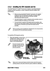
... CPU before you install the CPU fan and heatsink assembly. Narrow end of the groove pointing outward. (The photo shows the groove shaded for emphasis.) ASUS P5RD1-V Deluxe 2-9 If you install the heatsink and fan assembly.
... CPU before you install the CPU fan and heatsink assembly. Narrow end of the groove pointing outward. (The photo shows the groove shaded for emphasis.) ASUS P5RD1-V Deluxe 2-9 If you install the heatsink and fan assembly.

Motherboard Installation Guide
Page 35
2.3.3 Uninstalling the CPU heatsink and fan To uninstall the CPU heatsink and fan: 1. Pull up two fasteners at a time in a diagonal sequence to disengage the heatsink B and fan assembly from the connector on the motherboard. 2. A B A B B A ASUS P5RD1-V Deluxe 2-11 Disconnect the CPU fan cable from the A motherboard. Rotate each fastener counterclockwise. 3.
2.3.3 Uninstalling the CPU heatsink and fan To uninstall the CPU heatsink and fan: 1. Pull up two fasteners at a time in a diagonal sequence to disengage the heatsink B and fan assembly from the connector on the motherboard. 2. A B A B B A ASUS P5RD1-V Deluxe 2-11 Disconnect the CPU fan cable from the A motherboard. Rotate each fastener counterclockwise. 3.
Motherboard Installation Guide
Page 37
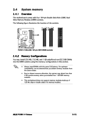
ASUS P5RD1-V Deluxe 2-13 The following figure illustrates the location of the sockets: P5RD1-V ® P5RD1-V DELUXE 184-pin DDR DIMM sockets 2.4.2 Memory Configurations You may detect less than 4 GB system memory when you obtain memory modules from the same vendor. • ...
ASUS P5RD1-V Deluxe 2-13 The following figure illustrates the location of the sockets: P5RD1-V ® P5RD1-V DELUXE 184-pin DDR DIMM sockets 2.4.2 Memory Configurations You may detect less than 4 GB system memory when you obtain memory modules from the same vendor. • ...
Motherboard Installation Guide
Page 41
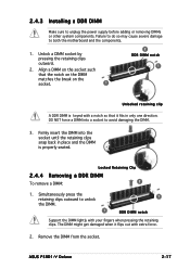
... the retaining clips outward to avoid damaging the DIMM. 3. The DIMM might get damaged when it fits in place and the DIMM is properly seated. ASUS P5RD1-V Deluxe 2-17 DO NOT force a DIMM into the socket until the retaining clips snap back in only one direction. Locked Retaining Clip 2.4.4 Removing a DDR DIMM To...
... the retaining clips outward to avoid damaging the DIMM. 3. The DIMM might get damaged when it fits in place and the DIMM is properly seated. ASUS P5RD1-V Deluxe 2-17 DO NOT force a DIMM into the socket until the retaining clips snap back in only one direction. Locked Retaining Clip 2.4.4 Removing a DDR DIMM To...
Motherboard Installation Guide
Page 43
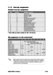
... 2 Onboard USB controller 3 Onboard USB 2.0 controller Onboard LAN Onboard HD audio A B C D E F G H - IRQ assignments for ISA or PCI devices. shared shared shared - - - shared shared shared shared - - - ASUS P5RD1-V Deluxe 2-19 shared - - - - - shared -- -- -- shared - - - - shared When using PCI cards on shared slots, ensure that the drivers support "Share IRQ" or that the cards do not...
... 2 Onboard USB controller 3 Onboard USB 2.0 controller Onboard LAN Onboard HD audio A B C D E F G H - IRQ assignments for ISA or PCI devices. shared shared shared - - - shared shared shared shared - - - ASUS P5RD1-V Deluxe 2-19 shared - - - - - shared -- -- -- shared - - - - shared When using PCI cards on shared slots, ensure that the drivers support "Share IRQ" or that the cards do not...

Motherboard Installation Guide
Page 45
... The onboard button cell battery powers the RAM data in CMOS. Move the jumper cap from pins 1-2 (default) to overclocking. P5RD1-V ® CLRTC 2 1 Normal (Default) 3 2 Clear CMOS P5RD1-V DELUXE Clear RTC RAM You do not need to clear the RTC when the system hangs due to pins 2-3. Shut down the key... Except when clearing the RTC RAM, never remove the cap on pins 2-3 for about 5~10 seconds, then move the cap back to default values. ASUS P5RD1-V Deluxe 2-21 To erase the RTC RAM: 1. Hold down and reboot the system so the BIOS can clear the CMOS memory of date, time, and ...
... The onboard button cell battery powers the RAM data in CMOS. Move the jumper cap from pins 1-2 (default) to overclocking. P5RD1-V ® CLRTC 2 1 Normal (Default) 3 2 Clear CMOS P5RD1-V DELUXE Clear RTC RAM You do not need to clear the RTC when the system hangs due to pins 2-3. Shut down the key... Except when clearing the RTC RAM, never remove the cap on pins 2-3 for about 5~10 seconds, then move the cap back to default values. ASUS P5RD1-V Deluxe 2-21 To erase the RTC RAM: 1. Hold down and reboot the system so the BIOS can clear the CMOS memory of date, time, and ...
Motherboard Installation Guide
Page 47
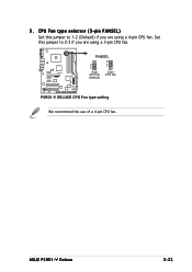
Set this jumper to 2-3 if you are using a 4-pin CPU fan. FANSEL P5RD1-V ® 2 1 4-pin CPU fan (Default) 3 2 3-pin CPU fan P5RD1-V DELUXE CPU Fan type setting We recommend the use of a 4-pin CPU fan. ASUS P5RD1-V Deluxe 2-23 3 . CPU Fan type selector (3-pin FANSEL) Set this jumper to 1-2 (Default) if you are using a 3-pin CPU fan.
Set this jumper to 2-3 if you are using a 4-pin CPU fan. FANSEL P5RD1-V ® 2 1 4-pin CPU fan (Default) 3 2 3-pin CPU fan P5RD1-V DELUXE CPU Fan type setting We recommend the use of a 4-pin CPU fan. ASUS P5RD1-V Deluxe 2-23 3 . CPU Fan type selector (3-pin FANSEL) Set this jumper to 1-2 (Default) if you are using a 3-pin CPU fan.
Motherboard Installation Guide
Page 49
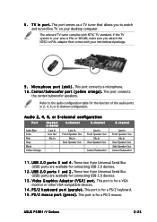
... sure you to -PAL adaptor that allows you attach the NTSC-to watch and record live TV on your area is for connecting USB 2.0 devices. 1 2 . ASUS P5RD1-V Deluxe 2-25 If the TV system in 2, 4, 6, or 8-channel configuration. T V I n p o r t . U S B 2 . 0 p o r t s 1 a n d 2 . This port serves as a TV tuner that comes with NTSC TV standard. These two 4-pin Universal...
... sure you to -PAL adaptor that allows you attach the NTSC-to watch and record live TV on your area is for connecting USB 2.0 devices. 1 2 . ASUS P5RD1-V Deluxe 2-25 If the TV system in 2, 4, 6, or 8-channel configuration. T V I n p o r t . U S B 2 . 0 p o r t s 1 a n d 2 . This port serves as a TV tuner that comes with NTSC TV standard. These two 4-pin Universal...
Motherboard Installation Guide
Page 51
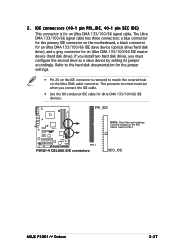
... connectors: a blue connector for the primary IDE connector on the Ultra DMA cable connector. SEC_IDE ASUS P5RD1-V Deluxe 2-27 IDE connectors (40-1 pin PRI_IDE, 40-1 pin SEC IDE) This connector is removed to PIN 1. PRI_IDE P5RD1-V ® PIN 1 P5RD1-V DELUXE IDE connectors NOTE: Orient the red markings (usually zigzag) on the IDE ribbon cable to match...
... connectors: a blue connector for the primary IDE connector on the Ultra DMA cable connector. SEC_IDE ASUS P5RD1-V Deluxe 2-27 IDE connectors (40-1 pin PRI_IDE, 40-1 pin SEC IDE) This connector is removed to PIN 1. PRI_IDE P5RD1-V ® PIN 1 P5RD1-V DELUXE IDE connectors NOTE: Orient the red markings (usually zigzag) on the IDE ribbon cable to match...
Motherboard Installation Guide
Page 53
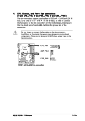
...; CPU_FAN CHA_FAN1 PWR_FAN CPU_FAN CPU FAN PWM CPU FAN IN CPU FAN PWR CHA_FAN1 Rotation +12V GND PWR_FAN GND +12V Rotation P5RD1-V DELUXE Fan connectors ASUS P5RD1-V Deluxe 2-29 CPU, Chassis, and Power fan connectors (4-pin CPU_FAN, 3-pin PWR_FAN, 3-pin CHA_FAN1) The fan connectors support cooling fans of 350 mA ~ 2000 mA (24 W ...
...; CPU_FAN CHA_FAN1 PWR_FAN CPU_FAN CPU FAN PWM CPU FAN IN CPU FAN PWR CHA_FAN1 Rotation +12V GND PWR_FAN GND +12V Rotation P5RD1-V DELUXE Fan connectors ASUS P5RD1-V Deluxe 2-29 CPU, Chassis, and Power fan connectors (4-pin CPU_FAN, 3-pin PWR_FAN, 3-pin CHA_FAN1) The fan connectors support cooling fans of 350 mA ~ 2000 mA (24 W ...
Motherboard Installation Guide
Page 55
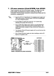
... ATX12V +12 Volts +12 Volts +12V DC +12V DC +5V Standby P5RD1-V ® GND GND Power OK Ground +5 Volts Ground +5 Volts Ground P5RD1-V DELUXE ATX power connectors +3 Volts +3 Volts Ground +5 Volts +5 Volts +5 Volts -5 Volts Ground Ground Ground PSON# Ground -12 Volts +3 Volts ASUS P5RD1-V Deluxe 2-31 7 . The system may become unstable or may not boot up...
... ATX12V +12 Volts +12 Volts +12V DC +12V DC +5V Standby P5RD1-V ® GND GND Power OK Ground +5 Volts Ground +5 Volts Ground P5RD1-V DELUXE ATX power connectors +3 Volts +3 Volts Ground +5 Volts +5 Volts +5 Volts -5 Volts Ground Ground Ground PSON# Ground -12 Volts +3 Volts ASUS P5RD1-V Deluxe 2-31 7 . The system may become unstable or may not boot up...

Motherboard Installation Guide
Page 57
...or switch cable to this connector. Doing so will damage the motherboard! CHASSIS P5RD1-V ® (Default) P5RD1-V DELUXE Chassis intrusion connector 11. IEEE 1394a connector (10-1 pin IE1394_1) This connector is removed or replaced. ASUS P5RD1-V Deluxe 2-33 The chassis intrusion sensor or switch sends a high-level signal to...Connect one end of the system chassis. +5VSB_MB Chassis Signal GND TPA1GND TPB1+12V GND TPA1+ GND TPB1+ +12V P5RD1-V ® IE1394_1 1 P5RD1-V DELUXE IEEE-1394 connector Never connect a U S B c a b l e to use the chassis intrusion detection feature.
...or switch cable to this connector. Doing so will damage the motherboard! CHASSIS P5RD1-V ® (Default) P5RD1-V DELUXE Chassis intrusion connector 11. IEEE 1394a connector (10-1 pin IE1394_1) This connector is removed or replaced. ASUS P5RD1-V Deluxe 2-33 The chassis intrusion sensor or switch sends a high-level signal to...Connect one end of the system chassis. +5VSB_MB Chassis Signal GND TPA1GND TPB1+12V GND TPA1+ GND TPB1+ +12V P5RD1-V ® IE1394_1 1 P5RD1-V DELUXE IEEE-1394 connector Never connect a U S B c a b l e to use the chassis intrusion detection feature.
Motherboard Installation Guide
Page 59
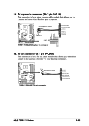
TV out connector (6-1 pin TV_OUT) This connector is for your computer. TV-out/capture-in module P5RD1-V ® Capture-in CAP_IN P5RD1-V DELUXE Capture-in connector GND S-video C-in S-video Y-in CVBS inputs GND GND GND TV S-OUT(S-Video) TV C-OUT(RCA Jack) CAP S-IN CAP C-IN CAP ...-out connector TV S-OUT TV C-OUT CAP S-IN(S Video) CAP C-IN(RCA Jack) CAP AL-IN(Audio Left) CAP AR-IN(Audio Right) ASUS P5RD1-V Deluxe 2-35 P5RD1-V ® TV-out TV-out/capture-in Left 15. 14. TV capture in connector (16-1 pin CAP_IN) This connector is for a TV out cable module ...
TV out connector (6-1 pin TV_OUT) This connector is for your computer. TV-out/capture-in module P5RD1-V ® Capture-in CAP_IN P5RD1-V DELUXE Capture-in connector GND S-video C-in S-video Y-in CVBS inputs GND GND GND TV S-OUT(S-Video) TV C-OUT(RCA Jack) CAP S-IN CAP C-IN CAP ...-out connector TV S-OUT TV C-OUT CAP S-IN(S Video) CAP C-IN(RCA Jack) CAP AL-IN(Audio Left) CAP AR-IN(Audio Right) ASUS P5RD1-V Deluxe 2-35 P5RD1-V ® TV-out TV-out/capture-in Left 15. 14. TV capture in connector (16-1 pin CAP_IN) This connector is for a TV out cable module ...


