P4GE-V User Manual
Page 8
... the BIOS parameters are also provided. • Chapter 5: Software support This chapter describes the contents of the support CD that you need when installing the ASUS P4GE-V motherboard. How this document. viii It includes brief descriptions of the special attributes of the motherboard and the new technology it supports. • Chapter 2: Hardware.... About this guide This user guide contains the information you have to change system settings through the BIOS Setup menus. It includes description of the P4GE-V motherboard.
... the BIOS parameters are also provided. • Chapter 5: Software support This chapter describes the contents of the support CD that you need when installing the ASUS P4GE-V motherboard. How this document. viii It includes brief descriptions of the special attributes of the motherboard and the new technology it supports. • Chapter 2: Hardware.... About this guide This user guide contains the information you have to change system settings through the BIOS Setup menus. It includes description of the P4GE-V motherboard.

P4GE-V User Manual
Page 14
Chapter summary 1.1 Welcome 1-1 1.2 Package contents 1-1 1.3 Special features 1-2 1.4 Motherboard overview 1-6 ASUS P4GE-V motherboard
Chapter summary 1.1 Welcome 1-1 1.2 Package contents 1-1 1.3 Special features 1-2 1.4 Motherboard overview 1-6 ASUS P4GE-V motherboard
P4GE-V User Manual
Page 15
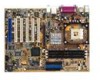
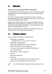
... the Intel® 82845GE chipset to get ahead in 478-pin package coupled with the list below. 1.2 Package contents Check your P4GE-V package for the following items. ASUS P4GE-V motherboard ATX form factor: 12 in x 9.0 in the long line of the above items is your perfect vehicle to set ... you start installing the motherboard, and hardware devices on it another standout in (30.5 cm x 22.9 cm) ASUS P4GE-V series support CD ASUS USB 2.0/GAME module (for audio models only) ASUS S/PDIF module (for audio models only) 80-conductor ribbon cables for UltraDMA/66/100 IDE drives 40-conductor IDE ...
... the Intel® 82845GE chipset to get ahead in 478-pin package coupled with the list below. 1.2 Package contents Check your P4GE-V package for the following items. ASUS P4GE-V motherboard ATX form factor: 12 in x 9.0 in the long line of the above items is your perfect vehicle to set ... you start installing the motherboard, and hardware devices on it another standout in (30.5 cm x 22.9 cm) ASUS P4GE-V series support CD ASUS USB 2.0/GAME module (for audio models only) ASUS S/PDIF module (for audio models only) 80-conductor ribbon cables for UltraDMA/66/100 IDE drives 40-conductor IDE ...
P4GE-V User Manual
Page 17
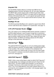
... The bundled Winbond Voice Editor software allows you use your existing power supply rather than buying a new ATX 12V power supply. ASUS P4GE-V motherboard user guide 1-3 Integrated VGA The Intel 845GE Graphics Memory Controller Hub (GMCH) has an integrated graphics controller that are also ...if any. When the system hangs due to open the system chassis and clear the RTC data. ASUS POST Reporter™ P4GE-V offers a new exciting feature called the ASUS POST Reporter™ to overclocking. The GMCH video engines support video conferencing and other video applications. The...
... The bundled Winbond Voice Editor software allows you use your existing power supply rather than buying a new ATX 12V power supply. ASUS P4GE-V motherboard user guide 1-3 Integrated VGA The Intel 845GE Graphics Memory Controller Hub (GMCH) has an integrated graphics controller that are also ...if any. When the system hangs due to open the system chassis and clear the RTC data. ASUS POST Reporter™ P4GE-V offers a new exciting feature called the ASUS POST Reporter™ to overclocking. The GMCH video engines support video conferencing and other video applications. The...

P4GE-V User Manual
Page 19
... (SFS) for more energy saving features for critical components. See page 4-30. Chassis intrusion detection The motherboard supports chassis intrusion monitoring through the ASUS ASIC. ACPI ready The Advanced Configuration power Interface (ACPI) provides more protection. See page 2-20. Overclocking • adjustable CPU frequency multiple in... from 100MHz up to prevent overheating and damage. Temperature, fan, and voltage monitoring The CPU temperature is monitored by the ASUS ASIC to 200MHz at 1MHz increments See page 4-17. ASUS P4GE-V motherboard user guide 1-5
... (SFS) for more energy saving features for critical components. See page 4-30. Chassis intrusion detection The motherboard supports chassis intrusion monitoring through the ASUS ASIC. ACPI ready The Advanced Configuration power Interface (ACPI) provides more protection. See page 2-20. Overclocking • adjustable CPU frequency multiple in... from 100MHz up to prevent overheating and damage. Temperature, fan, and voltage monitoring The CPU temperature is monitored by the ASUS ASIC to 200MHz at 1MHz increments See page 4-17. ASUS P4GE-V motherboard user guide 1-5
P4GE-V User Manual
Page 23
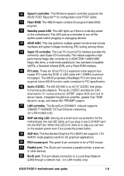
... Area Network (LAN) through a network hub. (on the system power even if you can turn off the system power before plugging or unplugging devices. 13 ASUS ASIC. The ADI AD1980 is for the motherboard, this LED is lit, there is a standby power on LAN models only) 18 AGP warning LED. This... 2.2 expansion slots support bus master PCI cards like SCSI or LAN cards with 133MB/s maximum throughput. Serving as a reminder to turn on LAN models only) ASUS P4GE-V motherboard user guide 1-9 This port allows connection to PCI specification. 16 Audio CODEC.
... Area Network (LAN) through a network hub. (on the system power even if you can turn off the system power before plugging or unplugging devices. 13 ASUS ASIC. The ADI AD1980 is for the motherboard, this LED is lit, there is a standby power on LAN models only) 18 AGP warning LED. This... 2.2 expansion slots support bus master PCI cards like SCSI or LAN cards with 133MB/s maximum throughput. Serving as a reminder to turn on LAN models only) ASUS P4GE-V motherboard user guide 1-9 This port allows connection to PCI specification. 16 Audio CODEC.

P4GE-V User Manual
Page 26
Chapter summary 2.1 Motherboard installation 2-1 2.2 Motherboard layout 2-2 2.3 Before you proceed 2-3 2.4 Central Processing Unit (CPU 2-4 2.5 System memory 2-10 2.6 Expansion slots 2-13 2.7 Jumpers 2-16 2.8 Connectors 2-18 ASUS P4GE-V motherboard
Chapter summary 2.1 Motherboard installation 2-1 2.2 Motherboard layout 2-2 2.3 Before you proceed 2-3 2.4 Central Processing Unit (CPU 2-4 2.5 System memory 2-10 2.6 Expansion slots 2-13 2.7 Jumpers 2-16 2.8 Connectors 2-18 ASUS P4GE-V motherboard

P4GE-V User Manual
Page 27
...and damage motherboard components. 2.1.1 Placement direction When installing the motherboard, make sure that you install the motherboard, study the configuration of the chassis ASUS P4GE-V motherboard user guide 2-1 Make sure to the rear part of the chassis as indicated in the image below. 2.1.2 Screw holes Place seven (7)...in the correct orientation. Do not overtighten the screws! Place this side towards the rear of your chassis to the chassis. The P4GE-V uses the ATX form factor that the motherboard fits into it into the holes indicated by circles to secure the motherboard to ensure...
...and damage motherboard components. 2.1.1 Placement direction When installing the motherboard, make sure that you install the motherboard, study the configuration of the chassis ASUS P4GE-V motherboard user guide 2-1 Make sure to the rear part of the chassis as indicated in the image below. 2.1.2 Screw holes Place seven (7)...in the correct orientation. Do not overtighten the screws! Place this side towards the rear of your chassis to the chassis. The P4GE-V uses the ATX form factor that the motherboard fits into it into the holes indicated by circles to secure the motherboard to ensure...

P4GE-V User Manual
Page 29
..., place it on them due to power up thus preventing the system to static electricity. 3. AGP_WARN1 ® P4GE-V P4GE-V Onboard LED ON Incorrect AGP Card OFF Correct AGP Card SB_PWR1 ON Standby Power OFF Powered Off ASUS P4GE-V motherboard user guide 2-3 Whenever you uninstall any 3.3V AGP card into the 1.5V AGP slot, this...
..., place it on them due to power up thus preventing the system to static electricity. 3. AGP_WARN1 ® P4GE-V P4GE-V Onboard LED ON Incorrect AGP Card OFF Correct AGP Card SB_PWR1 ON Standby Power OFF Powered Off ASUS P4GE-V motherboard user guide 2-3 Whenever you uninstall any 3.3V AGP card into the 1.5V AGP slot, this...

P4GE-V User Manual
Page 31
Locate the 478-pin ZIF socket on the motherboard. 2. ASUS P4GE-V motherboard user guide 2-5 Unlock the socket by pressing the lever sideways, then lift it up to 90°-100° angle, otherwise the CPU does not fit in completely. Socket Lever 90 - 100 Make sure that the socket lever is lifted up to install a CPU. 1. 2.4.2 Installing the CPU Follow these steps to a 90°-100° angle.
Locate the 478-pin ZIF socket on the motherboard. 2. ASUS P4GE-V motherboard user guide 2-5 Unlock the socket by pressing the lever sideways, then lift it up to 90°-100° angle, otherwise the CPU does not fit in completely. Socket Lever 90 - 100 Make sure that the socket lever is lifted up to install a CPU. 1. 2.4.2 Installing the CPU Follow these steps to a 90°-100° angle.

P4GE-V User Manual
Page 33
... buy a CPU separately, make sure that the heatsink fits properly on the motherboard upon purchase. Follow these steps to ensure optimum thermal condition and performance. ASUS P4GE-V motherboard user guide 2-7 2.4.3 Installing the heatsink and fan The Intel® Pentium® 4 Processor requires a specially designed heatsink and fan assembly to install the CPU...
... buy a CPU separately, make sure that the heatsink fits properly on the motherboard upon purchase. Follow these steps to ensure optimum thermal condition and performance. ASUS P4GE-V motherboard user guide 2-7 2.4.3 Installing the heatsink and fan The Intel® Pentium® 4 Processor requires a specially designed heatsink and fan assembly to install the CPU...

P4GE-V User Manual
Page 35
CPU Fan Connector (CPU_FAN1) Don't forget to the module base. ASUS P4GE-V motherboard user guide 2-9 Push down the locks on the motherboard labeled CPU_FAN1. Hardware monitoring errors may occur if you fail to the connector on the retention mechanism to secure the heatsink and fan to connect the CPU fan connector! 3. When secure, the retention locks should point to opposite directions. 2.4.4 Connecting the CPU fan cable When the fan, heatsink, and the retention mechanism are in place, connect the CPU fan cable to plug this connector.
CPU Fan Connector (CPU_FAN1) Don't forget to the module base. ASUS P4GE-V motherboard user guide 2-9 Push down the locks on the motherboard labeled CPU_FAN1. Hardware monitoring errors may occur if you fail to the connector on the retention mechanism to secure the heatsink and fan to connect the CPU fan connector! 3. When secure, the retention locks should point to opposite directions. 2.4.4 Connecting the CPU fan cable When the fan, heatsink, and the retention mechanism are in place, connect the CPU fan cable to plug this connector.

P4GE-V User Manual
Page 37
You may install single-sided DIMMs into the DIMM sockets. Double-sided DIMM DDR DIMM2 (Rows 2&3) DS SS DDR DIMM3 (Rows 3&2) None SS 1. ASUS P4GE-V motherboard user guide 2-11 DDR DIMM1 (Rows 0&1) SS/DS SS/DS * SS - 2.5.2 Memory configurations You may install any DDR DIMMs with 64MB, 128MB, 256MB, 512MB, ...
You may install single-sided DIMMs into the DIMM sockets. Double-sided DIMM DDR DIMM2 (Rows 2&3) DS SS DDR DIMM3 (Rows 3&2) None SS 1. ASUS P4GE-V motherboard user guide 2-11 DDR DIMM1 (Rows 0&1) SS/DS SS/DS * SS - 2.5.2 Memory configurations You may install any DDR DIMMs with 64MB, 128MB, 256MB, 512MB, ...
P4GE-V User Manual
Page 39
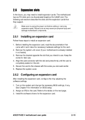
... expansion card After installing the expansion card, configure the it and make the necessary hardware settings for the expansion card. Turn on the next page. 3. ASUS P4GE-V motherboard user guide 2-13
... expansion card After installing the expansion card, configure the it and make the necessary hardware settings for the expansion card. Turn on the next page. 3. ASUS P4GE-V motherboard user guide 2-13

P4GE-V User Manual
Page 41
... buy an AGP card, make sure that they fit the AGP slot on your motherboard. Install only 1.5V AGP cards on this motherboard, including an ASUS proprietary BlueMagic PCI slot. Note the notches on a PCI slot. 2.6.4 AGP slot This motherboard has an Accelerated Graphics Port (AGP) slot that comply with +1.5V... that the card is lighted, you ask for one with PCI specifications. 2.6.3 PCI slots There are six 32-bit PCI slots on this motherboard! ® P4GE-V P4GE-V Accelerated Graphics Port (AGP) ASUS P4GE-V motherboard user guide 2-15
... buy an AGP card, make sure that they fit the AGP slot on your motherboard. Install only 1.5V AGP cards on this motherboard, including an ASUS proprietary BlueMagic PCI slot. Note the notches on a PCI slot. 2.6.4 AGP slot This motherboard has an Accelerated Graphics Port (AGP) slot that comply with +1.5V... that the card is lighted, you ask for one with PCI specifications. 2.6.3 PCI slots There are six 32-bit PCI slots on this motherboard! ® P4GE-V P4GE-V Accelerated Graphics Port (AGP) ASUS P4GE-V motherboard user guide 2-15
P4GE-V User Manual
Page 43
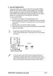
3. To erase the RTC RAM: 1. Keep the cap on CLRTC1 jumper default position. For system failure due to pins 1-2. 3. ASUS P4GE-V motherboard user guide 2-17 Removing the cap will cause system boot failure! ® P4GE-V P4GE-V Clear RTC RAM CLRTC1 12 23 Disable (Default) Enable You do not need to clear the RTC when the...
3. To erase the RTC RAM: 1. Keep the cap on CLRTC1 jumper default position. For system failure due to pins 1-2. 3. ASUS P4GE-V motherboard user guide 2-17 Removing the cap will cause system boot failure! ® P4GE-V P4GE-V Clear RTC RAM CLRTC1 12 23 Disable (Default) Enable You do not need to clear the RTC when the...

P4GE-V User Manual
Page 45
.../66 devices, purchase another for the secondary IDE connector. 1. Pin 20 on each IDE connector is intentional. ® P4GE-V NOTE: Orient the red markings (usually zigzag) on the UltraDMA cable connector. SEC_IDE PRI_IDE P4GE-V IDE Connectors PIN 1 PIN 1 For UltraDMA/100/66 IDE devices, use an 80-conductor IDE cable. You may... hole near the blue connector on the UltraDMA/100/66 cable is removed to match the covered hole on the IDE ribbon cable to PIN 1. 3. ASUS P4GE-V motherboard user guide 2-19
.../66 devices, purchase another for the secondary IDE connector. 1. Pin 20 on each IDE connector is intentional. ® P4GE-V NOTE: Orient the red markings (usually zigzag) on the UltraDMA cable connector. SEC_IDE PRI_IDE P4GE-V IDE Connectors PIN 1 PIN 1 For UltraDMA/100/66 IDE devices, use an 80-conductor IDE cable. You may... hole near the blue connector on the UltraDMA/100/66 cable is removed to match the covered hole on the IDE ribbon cable to PIN 1. 3. ASUS P4GE-V motherboard user guide 2-19

P4GE-V User Manual
Page 47
... connect to the CPU. Find the proper orientation and push down firmly until the connectors completely fit. The minimum recommended wattage is inadequate. ® P4GE-V ATXPWR1 EZ_PLUG1 Pin 1 +12.0VDC +5VSB PWR_OK GND +5.0VDC GND +5.0VDC GND +3.3VDC +3.3VDC +5.0VDC +5.0VDC -5.0VDC +12V GND GND ...+5V GND GND GND PS_ON# GND ATX12V1 -12.0VDC +3.3VDC +12V DC +12V DC GND GND P4GE-V ATX & Auxiliary Power Connectors ASUS P4GE-V motherboard user guide 2-21 The plugs from the power supply are using a standard ATX power supply that does not have the ATX ...
... connect to the CPU. Find the proper orientation and push down firmly until the connectors completely fit. The minimum recommended wattage is inadequate. ® P4GE-V ATXPWR1 EZ_PLUG1 Pin 1 +12.0VDC +5VSB PWR_OK GND +5.0VDC GND +5.0VDC GND +3.3VDC +3.3VDC +5.0VDC +5.0VDC -5.0VDC +12V GND GND ...+5V GND GND GND PS_ON# GND ATX12V1 -12.0VDC +3.3VDC +12V DC +12V DC GND GND P4GE-V ATX & Auxiliary Power Connectors ASUS P4GE-V motherboard user guide 2-21 The plugs from the power supply are using a standard ATX power supply that does not have the ATX ...
P4GE-V User Manual
Page 49
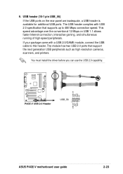
The module has two USB 2.0 ports that supports up to this header. USB+5V LP5LP5+ GND NC ® P4GE-V P4GE-V USB 2.0 Header USB_56 1 USB+5V LP4LP4+ GND ASUS P4GE-V motherboard user guide 2-23 The USB header complies with a USB 2.0/GAME module, connect the USB cable to 480 Mbps connection speed. USB header (10-1 pin ...
The module has two USB 2.0 ports that supports up to this header. USB+5V LP5LP5+ GND NC ® P4GE-V P4GE-V USB 2.0 Header USB_56 1 USB+5V LP4LP4+ GND ASUS P4GE-V motherboard user guide 2-23 The USB header complies with a USB 2.0/GAME module, connect the USB cable to 480 Mbps connection speed. USB header (10-1 pin ...

P4GE-V User Manual
Page 51
This module mounts to the pin definitions. ® P4GE-V IR_CON1 1 Front View Back View +5V IRRX GND IRTX P4GE-V Infrared Module Connector IRTX GND IRRX +5V (NC) 13. See section "4.4.2 I/O Device Configuration" for use with IR. Infrared module connector (5-1 pin ... transmitting and receiving infrared module. 12. Use the five pins as shown in BIOS to this feature. COM2 PIN 1 ® P4GE-V P4GE-V Serial COM2 Bracket ASUS P4GE-V motherboard user guide 2-25 Connect the bracket cable to set UART2 for details. You must also configure the UART2 Use As parameter ...
This module mounts to the pin definitions. ® P4GE-V IR_CON1 1 Front View Back View +5V IRRX GND IRTX P4GE-V Infrared Module Connector IRTX GND IRRX +5V (NC) 13. See section "4.4.2 I/O Device Configuration" for use with IR. Infrared module connector (5-1 pin ... transmitting and receiving infrared module. 12. Use the five pins as shown in BIOS to this feature. COM2 PIN 1 ® P4GE-V P4GE-V Serial COM2 Bracket ASUS P4GE-V motherboard user guide 2-25 Connect the bracket cable to set UART2 for details. You must also configure the UART2 Use As parameter ...

