
P4GE-V User Manual
Page 4
... 3: Powering up 3.1 Starting up for the first time 3-1 3.2 Vocal POST Messages 3-2 3.3 Powering off the computer 3-4 Chapter 4: BIOS setup 4.1 Managing and updating your BIOS 4-1 4.1.1 Using ASUS EZ Flash to update the BIOS 4-1 4.1.2 Using AFLASH to update the BIOS 4-3 4.2 BIOS Setup program 4-7 4.2.1 BIOS menu bar 4-8 4.2.2 Legend bar 4-8 4.3 Main Menu 4-10 4.3.1 Primary and Secondary Master/Slave 4-12 4.3.2 Keyboard Features 4-16...
... 3: Powering up 3.1 Starting up for the first time 3-1 3.2 Vocal POST Messages 3-2 3.3 Powering off the computer 3-4 Chapter 4: BIOS setup 4.1 Managing and updating your BIOS 4-1 4.1.1 Using ASUS EZ Flash to update the BIOS 4-1 4.1.2 Using AFLASH to update the BIOS 4-3 4.2 BIOS Setup program 4-7 4.2.1 BIOS menu bar 4-8 4.2.2 Legend bar 4-8 4.3 Main Menu 4-10 4.3.1 Primary and Secondary Master/Slave 4-12 4.3.2 Keyboard Features 4-16...
P4GE-V User Manual
Page 8
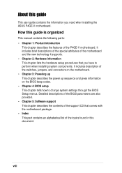
Detailed descriptions of the BIOS parameters are also provided. • Chapter 5: Software support This chapter describes the contents of the support CD that you need when installing the ASUS P4GE-V motherboard. It includes description of the motherboard and the new technology it supports. •...; Chapter 1: Product introduction This chapter describes the features of the P4GE-V motherboard. viii About this guide This user guide contains the information you have to change system settings through the BIOS Setup menus. It includes brief descriptions of the special attributes of ...
Detailed descriptions of the BIOS parameters are also provided. • Chapter 5: Software support This chapter describes the contents of the support CD that you need when installing the ASUS P4GE-V motherboard. It includes description of the motherboard and the new technology it supports. •...; Chapter 1: Product introduction This chapter describes the features of the P4GE-V motherboard. viii About this guide This user guide contains the information you have to change system settings through the BIOS Setup menus. It includes brief descriptions of the special attributes of ...

P4GE-V User Manual
Page 11
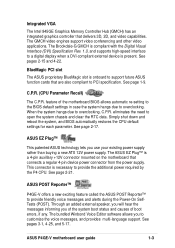
P4GE-V specifications summary CPU Chipset Front Side Bus (FSB) Memory Expansion slots VGA IDE Audio LAN Special features Rear panel I/O Socket 478 for Intel® Pentium&#... separately) 2 x UltraDMA 100/66/33 connectors ADI AD1980 6-channel audio CODEC Broadcom® BCM4401 Fast Ethernet controller ASUS JumperFree™ mode ASUS POST Reporter™ ASUS EZ Plug™ ASUS Q-Fan ASUS EZ Flash C.P.R. (CPU Parameter Recall) CrashFree BIOS Power Loss Restart SFS (Stepless Frequency Selection) CPU throttle Adjustable CPU VCORE, memory, and AGP voltages Multi...
P4GE-V specifications summary CPU Chipset Front Side Bus (FSB) Memory Expansion slots VGA IDE Audio LAN Special features Rear panel I/O Socket 478 for Intel® Pentium&#... separately) 2 x UltraDMA 100/66/33 connectors ADI AD1980 6-channel audio CODEC Broadcom® BCM4401 Fast Ethernet controller ASUS JumperFree™ mode ASUS POST Reporter™ ASUS EZ Plug™ ASUS Q-Fan ASUS EZ Flash C.P.R. (CPU Parameter Recall) CrashFree BIOS Power Loss Restart SFS (Stepless Frequency Selection) CPU throttle Adjustable CPU VCORE, memory, and AGP voltages Multi...

P4GE-V User Manual
Page 12
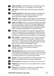
xii P4GE-V specifications summary Internal I/O BIOS features Industry standard Manageability Form Factor Support CD contents 1 x USB 2.0/1.1 connector for 2 additional USB ports CPU/Power/Chassis fan connectors 20-pin/4-pin ATX 12V ... connectors GAME/MIDI connector S/PDIF Out connector CD/AUX/Modem audio connectors Front panel audio connector 4Mb Flash ROM, Award BIOS, TCAV, PnP, DMI2.0, WfM2.0, SM BIOS2.3, Multi-language BIOS, ASUS EZ Flash, CrashFree BIOS, C.P.R. (CPU Parameter Recall) PCI 2.2, USB 2.0 WfM 2.0. DMI 2.0, WOL/WOR by PME, chassis intrusion, SMBus ATX form factor: 12 in...
xii P4GE-V specifications summary Internal I/O BIOS features Industry standard Manageability Form Factor Support CD contents 1 x USB 2.0/1.1 connector for 2 additional USB ports CPU/Power/Chassis fan connectors 20-pin/4-pin ATX 12V ... connectors GAME/MIDI connector S/PDIF Out connector CD/AUX/Modem audio connectors Front panel audio connector 4Mb Flash ROM, Award BIOS, TCAV, PnP, DMI2.0, WfM2.0, SM BIOS2.3, Multi-language BIOS, ASUS EZ Flash, CrashFree BIOS, C.P.R. (CPU Parameter Recall) PCI 2.2, USB 2.0 WfM 2.0. DMI 2.0, WOL/WOR by PME, chassis intrusion, SMBus ATX form factor: 12 in...
P4GE-V User Manual
Page 17
...new ATX 12V power supply. BlueMagic PCI slot The ASUS proprietary BlueMagic slot is onboard to support future ASUS function cards that are also compliant to overclocking. See page 2-17. See page 2-21. ASUS P4GE-V motherboard user guide 1-3 The GMCH video engines ...support video conferencing and other video applications. When the system hangs due to open the system chassis and clear the RTC data. ASUS EZ Plug™ This patented ASUS technology lets you of the system boot status and causes of the motherboard BIOS...
...new ATX 12V power supply. BlueMagic PCI slot The ASUS proprietary BlueMagic slot is onboard to support future ASUS function cards that are also compliant to overclocking. See page 2-17. See page 2-21. ASUS P4GE-V motherboard user guide 1-3 The GMCH video engines ...support video conferencing and other video applications. When the system hangs due to open the system chassis and clear the RTC data. ASUS EZ Plug™ This patented ASUS technology lets you of the system boot status and causes of the motherboard BIOS...

P4GE-V User Manual
Page 18
... buy a replacement ROM chip. 1-4 Chapter 1: Product introduction ASUS EZ Flash BIOS With the ASUS EZ Flash, you to personalize and add style to your choice from the available options. ASUS Multi-language BIOS The multi-language BIOS allows you to select the language of your system with customizable... eliminates the need to configure easier and faster. The localized BIOS menus allow you to use a DOS-based utility or boot from a floppy disk in the P4GE-V motherboard allows you can easily update the system BIOS even before loading the operating system. No need to ensure quiet...
... buy a replacement ROM chip. 1-4 Chapter 1: Product introduction ASUS EZ Flash BIOS With the ASUS EZ Flash, you to personalize and add style to your choice from the available options. ASUS Multi-language BIOS The multi-language BIOS allows you to select the language of your system with customizable... eliminates the need to configure easier and faster. The localized BIOS menus allow you to use a DOS-based utility or boot from a floppy disk in the P4GE-V motherboard allows you can easily update the system BIOS even before loading the operating system. No need to ensure quiet...

P4GE-V User Manual
Page 19
... Power Management (OSPM). See page 4-33. Chassis intrusion detection The motherboard supports chassis intrusion monitoring through the ASUS ASIC. ASUS P4GE-V motherboard user guide 1-5 The system voltage levels are monitored to prevent overheating and damage. ACPI ready The... Advanced Configuration power Interface (ACPI) provides more protection. See page 4-30. Temperature, fan, and voltage monitoring The CPU temperature is retained in BIOS using the ASUS...
... Power Management (OSPM). See page 4-33. Chassis intrusion detection The motherboard supports chassis intrusion monitoring through the ASUS ASIC. ASUS P4GE-V motherboard user guide 1-5 The system voltage levels are monitored to prevent overheating and damage. ACPI ready The... Advanced Configuration power Interface (ACPI) provides more protection. See page 4-30. Temperature, fan, and voltage monitoring The CPU temperature is retained in BIOS using the ASUS...
P4GE-V User Manual
Page 23
...on LAN models only) 18 AGP warning LED. The ASUS proprietary BlueMagic PCI slot (blue slot) supports future ASUS function cards compliant to turn on LAN models only) ASUS P4GE-V motherboard user guide 1-9 This Accelerated Graphics Port (...AGP) slot supports 1.5V AGP4X mode graphics cards for a 360K/720K/1.44M/2.88M floppy disk drive, a multi-mode parallel port, two standard compatible UARTs, a Standard Infrared (SIR), and a Flash ROM interface. 15 PCI slots. This 4Mb firmware contains the programmable BIOS...
...on LAN models only) 18 AGP warning LED. The ASUS proprietary BlueMagic PCI slot (blue slot) supports future ASUS function cards compliant to turn on LAN models only) ASUS P4GE-V motherboard user guide 1-9 This Accelerated Graphics Port (...AGP) slot supports 1.5V AGP4X mode graphics cards for a 360K/720K/1.44M/2.88M floppy disk drive, a multi-mode parallel port, two standard compatible UARTs, a Standard Infrared (SIR), and a Flash ROM interface. 15 PCI slots. This 4Mb firmware contains the programmable BIOS...

P4GE-V User Manual
Page 30
.... This motherboard supports Intel Pentium 4 CPUs with a surface mount 478-pin Zero Insertion Force (ZIF) socket. Install the CPU. 2. Note in BIOS to Enabled. Power up the system and enter BIOS Setup (see Chapter 4). The socket is supported under Windows XP and Linux 2.4.x (kernel) and later versions only. If you installed a CPU...
.... This motherboard supports Intel Pentium 4 CPUs with a surface mount 478-pin Zero Insertion Force (ZIF) socket. Install the CPU. 2. Note in BIOS to Enabled. Power up the system and enter BIOS Setup (see Chapter 4). The socket is supported under Windows XP and Linux 2.4.x (kernel) and later versions only. If you installed a CPU...
P4GE-V User Manual
Page 39
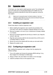
... adding or removing expansion cards. Failure to do so may need to install expansion cards. Install the software drivers for the card. 2. ASUS P4GE-V motherboard user guide 2-13 Secure the card to the card. Assign an IRQ to the chassis with it by adjusting the software settings.... later use . Remove the bracket opposite the slot that they support. Keep the screw for information on the system and change the necessary BIOS settings, if any. Replace the system cover. 2.6.2 Configuring an expansion card After installing the expansion card, configure the it and make the...
... adding or removing expansion cards. Failure to do so may need to install expansion cards. Install the software drivers for the card. 2. ASUS P4GE-V motherboard user guide 2-13 Secure the card to the card. Assign an IRQ to the chassis with it by adjusting the software settings.... later use . Remove the bracket opposite the slot that they support. Keep the screw for information on the system and change the necessary BIOS settings, if any. Replace the system cover. 2.6.2 Configuring an expansion card After installing the expansion card, configure the it and make the...

P4GE-V User Manual
Page 42
... wish to enable or disable the keyboard wake-up the computer when you to wake up feature. DO NOT change the default settings. ® P4GE-V P4GE-V WPCI_USB Setting WPCI_USB 31 53 42 Wireless PCI_USB 64 Original PCI reserved pin (Default) 2-16 Chapter 2: Hardware information 2.7 Jumpers 1. This feature...jumpers are reserved. Keyboard power (3-pin KBPWR1) This jumper allows you press a key on the +5VSB lead, and a corresponding setting in the BIOS (see section 4.5.1 Power Up Control). KBPWR1 12 23 P4GE-V +5V +5VSB ® (Default) P4GE-V Keyboard Power Setting 2.
... wish to enable or disable the keyboard wake-up the computer when you to wake up feature. DO NOT change the default settings. ® P4GE-V P4GE-V WPCI_USB Setting WPCI_USB 31 53 42 Wireless PCI_USB 64 Original PCI reserved pin (Default) 2-16 Chapter 2: Hardware information 2.7 Jumpers 1. This feature...jumpers are reserved. Keyboard power (3-pin KBPWR1) This jumper allows you press a key on the +5VSB lead, and a corresponding setting in the BIOS (see section 4.5.1 Power Up Control). KBPWR1 12 23 P4GE-V +5V +5VSB ® (Default) P4GE-V Keyboard Power Setting 2.
P4GE-V User Manual
Page 43
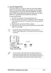
... 1. Except when clearing the RTC RAM, never remove the cap on pins 2-3 for about 5~10 seconds, then move the cap back to pins 1-2. 3. ASUS P4GE-V motherboard user guide 2-17 Clear RTC RAM (CLRTC1) This jumper allows you to re-enter data. Shut down the key during the boot process and...RTC when the system hangs due to default values. Keep the cap on CLRTC1 jumper default position. Hold down and reboot the system so BIOS can clear the CMOS memory of date, time, and system setup parameters by the onboard button cell battery. You can automatically reset parameter ...
... 1. Except when clearing the RTC RAM, never remove the cap on pins 2-3 for about 5~10 seconds, then move the cap back to pins 1-2. 3. ASUS P4GE-V motherboard user guide 2-17 Clear RTC RAM (CLRTC1) This jumper allows you to re-enter data. Shut down the key during the boot process and...RTC when the system hangs due to default values. Keep the cap on CLRTC1 jumper default position. Hold down and reboot the system so BIOS can clear the CMOS memory of date, time, and system setup parameters by the onboard button cell battery. You can automatically reset parameter ...

P4GE-V User Manual
Page 45
... the IDE ribbon cable to be both master devices with two ribbon cables - SEC_IDE PRI_IDE P4GE-V IDE Connectors PIN 1 PIN 1 For UltraDMA/100/66 IDE devices, use an 80-conductor IDE cable. 3. BIOS supports specific device bootup. ASUS P4GE-V motherboard user guide 2-19 one for the jumper settings. The UltraDMA/66 cable included in...
... the IDE ribbon cable to be both master devices with two ribbon cables - SEC_IDE PRI_IDE P4GE-V IDE Connectors PIN 1 PIN 1 For UltraDMA/100/66 IDE devices, use an 80-conductor IDE cable. 3. BIOS supports specific device bootup. ASUS P4GE-V motherboard user guide 2-19 one for the jumper settings. The UltraDMA/66 cable included in...

P4GE-V User Manual
Page 51
12. COM2 PIN 1 ® P4GE-V P4GE-V Serial COM2 Bracket ASUS P4GE-V motherboard user guide 2-25 You must also configure the UART2 Use As parameter in Back View and connect a ribbon cable from the module to the motherboard SIR connector according to set UART2 for details. Use the five pins as shown in BIOS to the pin...
12. COM2 PIN 1 ® P4GE-V P4GE-V Serial COM2 Bracket ASUS P4GE-V motherboard user guide 2-25 You must also configure the UART2 Use As parameter in Back View and connect a ribbon cable from the module to the motherboard SIR connector according to set UART2 for details. Use the five pins as shown in BIOS to the pin...

P4GE-V User Manual
Page 53
...save power and to the system power LED. System panel connector (20-pin PANEL1) This connector accommodates several system front panel functions. ASUS P4GE-V motherboard user guide 2-27 16. P4GE-V System Panel Connectors • System Power LED Lead (3-1 pin PLED) This 3-1 pin connector connects to expand the life of ... power. Keyboard Lock Speaker Power LED Connector +5 V PLED Keylock Ground +5V Ground Ground Speaker ExtSMI# Ground PWRBIN Ground Reset Ground ® P4GE-V Reset SW SMI Lead ATX Power Switch* * Requires an ATX power supply. The LED lights up when you turn on the...
...save power and to the system power LED. System panel connector (20-pin PANEL1) This connector accommodates several system front panel functions. ASUS P4GE-V motherboard user guide 2-27 16. P4GE-V System Panel Connectors • System Power LED Lead (3-1 pin PLED) This 3-1 pin connector connects to expand the life of ... power. Keyboard Lock Speaker Power LED Connector +5 V PLED Keylock Ground +5V Ground Ground Speaker ExtSMI# Ground PWRBIN Ground Reset Ground ® P4GE-V Reset SW SMI Lead ATX Power Switch* * Requires an ATX power supply. The LED lights up when you turn on the...

P4GE-V User Manual
Page 55
Powering up sequence and gives information on the BIOS beep codes. Chapter 3 This chapter describes the power up
Powering up sequence and gives information on the BIOS beep codes. Chapter 3 This chapter describes the power up

P4GE-V User Manual
Page 57
... making all switches are running at the back of the chassis). 6. ASUS P4GE-V motherboard user guide 3-1 Turn on the front of the system chassis. 4. System power (if you are using an ATX power supply, you need to enter BIOS Setup. Award BIOS Beep Codes Beep One short beep when displaying logo Long beeps in...
... making all switches are running at the back of the chassis). 6. ASUS P4GE-V motherboard user guide 3-1 Turn on the front of the system chassis. 4. System power (if you are using an ATX power supply, you need to enter BIOS Setup. Award BIOS Beep Codes Beep One short beep when displaying logo Long beeps in...
P4GE-V User Manual
Page 58
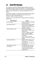
...VGA test System failed due to support a special feature called the ASUS POST Reporter™. You can record your CPU settings in BIOS and make sure you only set to section "2.5 System memory" for assistance. See the "ASUS contact information" on page x. • Install 184-pin unbuffered PC2700...over-clocking Action • Install an Intel Pentium 4 Processor into the CPU socket. • Check the CPU if properly installed. • Call ASUS technical support for instruction on installing a DIMM. • Install a PCI VGA card into one of system events and boot status. These POST ...
...VGA test System failed due to support a special feature called the ASUS POST Reporter™. You can record your CPU settings in BIOS and make sure you only set to section "2.5 System memory" for assistance. See the "ASUS contact information" on page x. • Install 184-pin unbuffered PC2700...over-clocking Action • Install an Intel Pentium 4 Processor into the CPU socket. • Check the CPU if properly installed. • Call ASUS technical support for instruction on installing a DIMM. • Install a PCI VGA card into one of system events and boot status. These POST ...

P4GE-V User Manual
Page 59
...Test • No action required Computer now booting from operating • No action required system You may disable the ASUS POST Reporter™ in the BIOS setup. ASUS P4GE-V motherboard user guide 3-3 No IDE hard disk detected • Make sure you applied power to the system. ... fan failed • Check the CPU fan and make sure it turns on the motherboard. • See section "2.8 Connectors." See the "ASUS contact information" on the rear panel. • See section "1.4.1 Major components" for assistance. See section "4.4.2 I/O Device Configuration". CPU voltage out...
...Test • No action required Computer now booting from operating • No action required system You may disable the ASUS POST Reporter™ in the BIOS setup. ASUS P4GE-V motherboard user guide 3-3 No IDE hard disk detected • Make sure you applied power to the system. ... fan failed • Check the CPU fan and make sure it turns on the motherboard. • See section "2.8 Connectors." See the "ASUS contact information" on the rear panel. • See section "1.4.1 Major components" for assistance. See section "4.4.2 I/O Device Configuration". CPU voltage out...

P4GE-V User Manual
Page 61
Chapter 4 This chapter tells how to change system settings through the BIOS Setup menus. Detailed descriptions of the BIOS parameters are also provided. BIOS setup
Chapter 4 This chapter tells how to change system settings through the BIOS Setup menus. Detailed descriptions of the BIOS parameters are also provided. BIOS setup


