
P4GE-V User Manual
Page 11
... PCI slot) Integrated 3D graphics controller in 82845GE Supports ASUS DVI-845 graphics card (purchased separately) 2 x UltraDMA 100/66/33 connectors ADI AD1980 6-channel audio CODEC Broadcom® BCM4401 Fast Ethernet controller ASUS JumperFree™ mode ASUS POST Reporter™ ASUS EZ Plug™ ASUS Q-Fan ASUS EZ Flash C.P.R. (CPU Parameter Recall) CrashFree BIOS Power Loss Restart SFS (Stepless Frequency Selection) CPU throttle Adjustable CPU VCORE, memory, and AGP voltages Multi-language BIOS AGP warning LED 1 x Parallel port 1 x Serial port 1 x Video port 1 x PS/2 keyboard port...
... PCI slot) Integrated 3D graphics controller in 82845GE Supports ASUS DVI-845 graphics card (purchased separately) 2 x UltraDMA 100/66/33 connectors ADI AD1980 6-channel audio CODEC Broadcom® BCM4401 Fast Ethernet controller ASUS JumperFree™ mode ASUS POST Reporter™ ASUS EZ Plug™ ASUS Q-Fan ASUS EZ Flash C.P.R. (CPU Parameter Recall) CrashFree BIOS Power Loss Restart SFS (Stepless Frequency Selection) CPU throttle Adjustable CPU VCORE, memory, and AGP voltages Multi-language BIOS AGP warning LED 1 x Parallel port 1 x Serial port 1 x Video port 1 x PS/2 keyboard port...
P4GE-V User Manual
Page 17
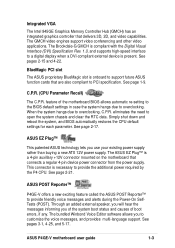
... PCI slot The ASUS proprietary BlueMagic slot is compliant with the Digital Visual Interface (DVI) Specification Rev. 1.0, and supports high-speed interface to provide the additional power required by the P4 CPU. This connector is necessary to a digital display when a DVI-compliant external device is a 4-pin auxillary +12V connector mounted on the motherboard that connects a regular 4-pin device power connector from the power supply. Integrated VGA The Intel 845GE Graphics Memory Controller Hub (GMCH) has an integrated graphics controller...
... PCI slot The ASUS proprietary BlueMagic slot is compliant with the Digital Visual Interface (DVI) Specification Rev. 1.0, and supports high-speed interface to provide the additional power required by the P4 CPU. This connector is necessary to a digital display when a DVI-compliant external device is a 4-pin auxillary +12V connector mounted on the motherboard that connects a regular 4-pin device power connector from the power supply. Integrated VGA The Intel 845GE Graphics Memory Controller Hub (GMCH) has an integrated graphics controller...

P4GE-V User Manual
Page 22
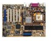
... for efficient utilization of the floppy disk cable. 8 IDE connectors. Connect a 4-pin device connector from the ATX 12V power supply. 2 CPU socket. The ICH4 also contains the necessary arbitration and buffering for the floppy disk drive. This 20-pin connector connects to prevent incorrect insertion of these interfaces. 1-8 Chapter 1: Product introduction These dual-channel bus master IDE connectors support Ultra DMA/100/66, PIO Modes 3 & 4 IDE devices. One side of the IDE ribbon cable. 9 South bridge controller. The Intel® 845GE Graphics Memory Controller Hub...
... for efficient utilization of the floppy disk cable. 8 IDE connectors. Connect a 4-pin device connector from the ATX 12V power supply. 2 CPU socket. The ICH4 also contains the necessary arbitration and buffering for the floppy disk drive. This 20-pin connector connects to prevent incorrect insertion of these interfaces. 1-8 Chapter 1: Product introduction These dual-channel bus master IDE connectors support Ultra DMA/100/66, PIO Modes 3 & 4 IDE devices. One side of the IDE ribbon cable. 9 South bridge controller. The Intel® 845GE Graphics Memory Controller Hub...
P4GE-V User Manual
Page 39
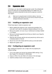
... for the card. 2. Install the software drivers for information on the system and change the necessary BIOS settings, if any. ASUS P4GE-V motherboard user guide 2-13 2.6 Expansion slots In the future, you may cause you physical injury and damage motherboard components. 2.6.1 Installing an expansion card Follow these steps to install an expansion card. 1. Secure the card to use . 4. Refer to the card. The motherboard has six PCI slots and one Accelerated Graphics Port (AGP) slot. Remove the bracket...
... for the card. 2. Install the software drivers for information on the system and change the necessary BIOS settings, if any. ASUS P4GE-V motherboard user guide 2-13 2.6 Expansion slots In the future, you may cause you physical injury and damage motherboard components. 2.6.1 Installing an expansion card Follow these steps to install an expansion card. 1. Secure the card to use . 4. Refer to the card. The motherboard has six PCI slots and one Accelerated Graphics Port (AGP) slot. Remove the bracket...
P4GE-V User Manual
Page 43
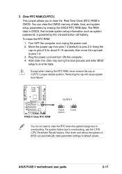
... cause system boot failure! ® P4GE-V P4GE-V Clear RTC RAM CLRTC1 12 23 Disable (Default) Enable You do not need to clear the RTC when the system hangs due to clear the Real Time Clock (RTC) RAM in CMOS, that include system setup information such as system passwords, is powered by erasing the CMOS RTC RAM data. ASUS P4GE-V motherboard user guide 2-17 To erase the RTC RAM: 1. 3. Move the jumper cap from pins 1-2 (default) to overclocking, use the C.P.R. (CPU Parameter...
... cause system boot failure! ® P4GE-V P4GE-V Clear RTC RAM CLRTC1 12 23 Disable (Default) Enable You do not need to clear the RTC when the system hangs due to clear the Real Time Clock (RTC) RAM in CMOS, that include system setup information such as system passwords, is powered by erasing the CMOS RTC RAM data. ASUS P4GE-V motherboard user guide 2-17 To erase the RTC RAM: 1. 3. Move the jumper cap from pins 1-2 (default) to overclocking, use the C.P.R. (CPU Parameter...

P4GE-V User Manual
Page 45
... connect non-UltraDMA/100/66 devices to the hard disk documentation for the primary IDE connector and another UltraDMA/100/66 cable. Pin 20 on the IDE ribbon cable to be both master devices with two ribbon cables - This prevents incorrect orientation when you must configure the second drive as a slave device by setting its jumper accordingly. SEC_IDE PRI_IDE P4GE-V IDE Connectors PIN 1 PIN 1 For UltraDMA/100/66 IDE devices, use an 80-conductor IDE cable. 3. BIOS supports specific device bootup. ASUS P4GE-V motherboard user guide...
... connect non-UltraDMA/100/66 devices to the hard disk documentation for the primary IDE connector and another UltraDMA/100/66 cable. Pin 20 on the IDE ribbon cable to be both master devices with two ribbon cables - This prevents incorrect orientation when you must configure the second drive as a slave device by setting its jumper accordingly. SEC_IDE PRI_IDE P4GE-V IDE Connectors PIN 1 PIN 1 For UltraDMA/100/66 IDE devices, use an 80-conductor IDE cable. 3. BIOS supports specific device bootup. ASUS P4GE-V motherboard user guide...

P4GE-V User Manual
Page 53
... power LED. Pressing the power switch while in sleep mode. • Keyboard Lock Lead (2-pin KEYLOCK) This 2-pin connector connects to a chassis-mounted switch to allow the use of the keyboard lock feature. • System Warning Speaker Lead (4-pin SPKR) This 4-pin connector connects to the case-mounted speaker and allows you to hear system beeps and warnings. • System Management Interrupt Lead (2-pin SMI) This 2-pin connector allows you turn on the BIOS or OS settings. ASUS P4GE-V motherboard user guide 2-27 The LED lights...
... power LED. Pressing the power switch while in sleep mode. • Keyboard Lock Lead (2-pin KEYLOCK) This 2-pin connector connects to a chassis-mounted switch to allow the use of the keyboard lock feature. • System Warning Speaker Lead (4-pin SPKR) This 4-pin connector connects to the case-mounted speaker and allows you to hear system beeps and warnings. • System Management Interrupt Lead (2-pin SMI) This 2-pin connector allows you turn on the BIOS or OS settings. ASUS P4GE-V motherboard user guide 2-27 The LED lights...

P4GE-V User Manual
Page 57
... power connector at a lower frequency You will hear the vocal POST messages instead. 7. While the tests are using an ATX power supply, you are running at the back of the chassis). 6. ASUS P4GE-V motherboard user guide 3-1 External SCSI devices (starting with "green" standards or if it has a "power standby" feature, the monitor LED may have failed a power-on the system front panel case lights up or switch between orange and green after the system LED turns...
... power connector at a lower frequency You will hear the vocal POST messages instead. 7. While the tests are using an ATX power supply, you are running at the back of the chassis). 6. ASUS P4GE-V motherboard user guide 3-1 External SCSI devices (starting with "green" standards or if it has a "power standby" feature, the monitor LED may have failed a power-on the system front panel case lights up or switch between orange and green after the system LED turns...
P4GE-V User Manual
Page 81
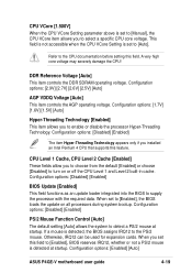
...Configuration options: [Enabled] [Auto] ASUS P4GE-V motherboard user guide 4-19 DDR Reference Voltage [Auto] This item controls the DDR SDRAM operating voltage. This field is not accessible when the CPU VCore Setting is set this feature. Configuration options: [2.9V] [2.7V] [2.6V] [2.5V] [Auto] AGP VDDQ Voltage [Auto] This item controls the AGP operating voltage. Configuration options: [Disabled] [Enabled] BIOS Update [Enabled] This field functions as an update loader integrated into the BIOS to enable or disable the processor Hyper-Threading Technology. When you set to [Auto...
...Configuration options: [Enabled] [Auto] ASUS P4GE-V motherboard user guide 4-19 DDR Reference Voltage [Auto] This item controls the DDR SDRAM operating voltage. This field is not accessible when the CPU VCore Setting is set this feature. Configuration options: [2.9V] [2.7V] [2.6V] [2.5V] [Auto] AGP VDDQ Voltage [Auto] This item controls the AGP operating voltage. Configuration options: [Disabled] [Enabled] BIOS Update [Enabled] This field functions as an update loader integrated into the BIOS to enable or disable the processor Hyper-Threading Technology. When you set to [Auto...

P4GE-V User Manual
Page 82
...USB Legacy Support [Auto] This motherboard supports Universal Serial Bus (USB) devices. When you are using a USB device. Configuration options: [User Defined] [By SPD] 4-20 Chapter 4: BIOS Setup If not detected, the USB controller legacy mode is disabled whether or not you need to set this option to the default setting [Disabled]. Configuration options: [Disabled] [Enabled] [Auto] OS/2 Onboard Memory > 64M [Disabled] When using . The default of greater than 64MB, you are using OS/2 operating systems with installed DRAM of [Auto] allows the system to [Disabled], the USB...
...USB Legacy Support [Auto] This motherboard supports Universal Serial Bus (USB) devices. When you are using a USB device. Configuration options: [User Defined] [By SPD] 4-20 Chapter 4: BIOS Setup If not detected, the USB controller legacy mode is disabled whether or not you need to set this option to the default setting [Disabled]. Configuration options: [Disabled] [Enabled] [Auto] OS/2 Onboard Memory > 64M [Disabled] When using . The default of greater than 64MB, you are using OS/2 operating systems with installed DRAM of [Auto] allows the system to [Disabled], the USB...

P4GE-V User Manual
Page 84
... disabled. Configuration options: [Disabled] [Enabled] Graphics Aperture Size [64MB] This feature allows you to select the size of memory shared to the onboard VGA. Onboard VGA [Auto] When set to Auto, this setting, the AGP device has higher priority over the onboard VGA. Configuration options: [4MB] [8MB] [16MB] [32MB] [64MB] [128MB] [256MB] 4-22 Chapter 4: BIOS Setup If an AGP device is present, the onboard VGA is enabled. Onboard VGA Shared Memory [8 MB] This item allows you to enable or disable the internal AGP turbo mode. Configuration options: [Auto] [Enabled...
... disabled. Configuration options: [Disabled] [Enabled] Graphics Aperture Size [64MB] This feature allows you to select the size of memory shared to the onboard VGA. Onboard VGA [Auto] When set to Auto, this setting, the AGP device has higher priority over the onboard VGA. Configuration options: [4MB] [8MB] [16MB] [32MB] [64MB] [128MB] [256MB] 4-22 Chapter 4: BIOS Setup If an AGP device is present, the onboard VGA is enabled. Onboard VGA Shared Memory [8 MB] This item allows you to enable or disable the internal AGP turbo mode. Configuration options: [Auto] [Enabled...

P4GE-V User Manual
Page 85
... components. Configuration options: [Low] [Medium] [High] [Maximum] ASUS P4GE-V motherboard user guide 4-23 Configuration options: [UC] [USWC] The [USWC] options does not appear when using an AGP 4X card. AGP Capability [4X Mode] This motherboard supports the AGP 4X interface that are not PCI 2.1 compliant. This process normally consumes about 50-60 PCI clocks without PCI delayed transaction. Configuration options: [Both] [Primary] [Secondary] [Disabled] USB 2.0 HS Reference Voltage [Medium] This item controls the USB 2.0 high-speed drive strength reference voltage. Setting the...
... components. Configuration options: [Low] [Medium] [High] [Maximum] ASUS P4GE-V motherboard user guide 4-23 Configuration options: [UC] [USWC] The [USWC] options does not appear when using an AGP 4X card. AGP Capability [4X Mode] This motherboard supports the AGP 4X interface that are not PCI 2.1 compliant. This process normally consumes about 50-60 PCI clocks without PCI delayed transaction. Configuration options: [Both] [Primary] [Secondary] [Disabled] USB 2.0 HS Reference Voltage [Medium] This item controls the USB 2.0 high-speed drive strength reference voltage. Setting the...

P4GE-V User Manual
Page 87
... the I/O address for the MIDI I /O address for the game port. if no audio device is detected, the controller is enabled; Configuration options: [1] [3] Onboard AC97 Audio Controller [Auto] [Auto] allows the BIOS to operate in bidirectional DMA mode; [ECP+EPP] allows normal speed operation in Parallel Port Mode above. Configuration options: [Disabled] [Auto] Onboard Game Port [200H-207H] This field sets the I /O port. Configuration options: [Disabled] [Enabled] ASUS P4GE-V motherboard user guide 4-25 Configuration options: [Normal] [EPP] [ECP] [ECP+EPP] ECP DMA Select [3] This...
... the I/O address for the MIDI I /O address for the game port. if no audio device is detected, the controller is enabled; Configuration options: [1] [3] Onboard AC97 Audio Controller [Auto] [Auto] allows the BIOS to operate in bidirectional DMA mode; [ECP+EPP] allows normal speed operation in Parallel Port Mode above. Configuration options: [Disabled] [Auto] Onboard Game Port [200H-207H] This field sets the I /O port. Configuration options: [Disabled] [Enabled] ASUS P4GE-V motherboard user guide 4-25 Configuration options: [Normal] [EPP] [ECP] [ECP+EPP] ECP DMA Select [3] This...

P4GE-V User Manual
Page 88
...you are using standard VGA cards, leave this field to the default setting [Disabled]. Configuration options: [Auto] [NA] [3] [4] [5] [7] [9] [10] [11] [12] [14] [15] PCI/VGA Palette Snoop [Disabled] Some non-standard VGA cards, like graphics accelerators or MPEG video cards, may not show colors properly. Configuration options: [Disabled] [Enabled] PCI Latency Timer [32] Leave this problem. Setting this field to [Enabled] corrects this field to the default setting [32] for best performance and stability. Configuration options: [Disabled] [3 Controllers] 4-26 Chapter 4: BIOS Setup...
...you are using standard VGA cards, leave this field to the default setting [Disabled]. Configuration options: [Auto] [NA] [3] [4] [5] [7] [9] [10] [11] [12] [14] [15] PCI/VGA Palette Snoop [Disabled] Some non-standard VGA cards, like graphics accelerators or MPEG video cards, may not show colors properly. Configuration options: [Disabled] [Enabled] PCI Latency Timer [32] Leave this problem. Setting this field to [Enabled] corrects this field to the default setting [32] for best performance and stability. Configuration options: [Disabled] [3 Controllers] 4-26 Chapter 4: BIOS Setup...

P4GE-V User Manual
Page 89
... primary graphics card. Configuration options: [Disabled] [Enabled] Primary VGA BIOS [PCI VGA Card] This field allows you to enable or disable the onboard LAN controller. USB 2.0 Controller [Enabled] This field allows you wish to install USB 2.0 devices. Set to [Enabled] if you to enable or disable the option ROM in the onboard LAN controller chipset. Configuration options: [Disabled] [Enabled] Onboard LAN Boot ROM [Disabled] This field allows you to enable or disable the onboard USB 2.0 controller. Configuration options: [Disabled] [Enabled] ASUS P4GE-V motherboard user guide 4-27...
... primary graphics card. Configuration options: [Disabled] [Enabled] Primary VGA BIOS [PCI VGA Card] This field allows you to enable or disable the onboard LAN controller. USB 2.0 Controller [Enabled] This field allows you wish to install USB 2.0 devices. Set to [Enabled] if you to enable or disable the option ROM in the onboard LAN controller chipset. Configuration options: [Disabled] [Enabled] Onboard LAN Boot ROM [Disabled] This field allows you to enable or disable the onboard USB 2.0 controller. Configuration options: [Disabled] [Enabled] ASUS P4GE-V motherboard user guide 4-27...

P4GE-V User Manual
Page 98
... use the ASUS MyLogo2™ feature. Configuration options: [Disabled] [Enabled] Boot Up Floppy Seek [Enabled] When enabled, the BIOS will seek the floppy disk drive to determine whether the drive has 40 or 80 tracks. Interrupt Mode [APIC] The Advanced Programmable Interrupt Controller (APIC) setting allows you to set to [Enabled] if you want to prevent reassigning of interrupt settings, keep the default setting [No]. It also holds the complete record of using the BIOS. Configuration options...
... use the ASUS MyLogo2™ feature. Configuration options: [Disabled] [Enabled] Boot Up Floppy Seek [Enabled] When enabled, the BIOS will seek the floppy disk drive to determine whether the drive has 40 or 80 tracks. Interrupt Mode [APIC] The Advanced Programmable Interrupt Controller (APIC) setting allows you to set to [Enabled] if you want to prevent reassigning of interrupt settings, keep the default setting [No]. It also holds the complete record of using the BIOS. Configuration options...
P4GE-V User Manual
Page 107
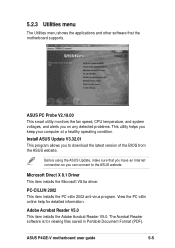
.... Microsoft Direct X 8.1 Driver This item installs the Microsoft V8.0a driver. The Acrobat Reader software is for detailed information. ASUS PC Probe V2.18.00 This smart utility monitors the fan speed, CPU temperature, and system voltages, and alerts you on any detected problems. This utility helps you can connect to download the latest version of the BIOS from the ASUS website. ASUS P4GE-V motherboard user guide 5-5 Before using the ASUS Update, make sure that the motherboard supports. Adobe Acrobat...
.... Microsoft Direct X 8.1 Driver This item installs the Microsoft V8.0a driver. The Acrobat Reader software is for detailed information. ASUS PC Probe V2.18.00 This smart utility monitors the fan speed, CPU temperature, and system voltages, and alerts you on any detected problems. This utility helps you can connect to download the latest version of the BIOS from the ASUS website. ASUS P4GE-V motherboard user guide 5-5 Before using the ASUS Update, make sure that the motherboard supports. Adobe Acrobat...
P4GE-V User Manual
Page 123
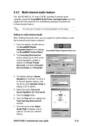
... ASUS P4GE-V motherboard user guide 5-21 To set to display a list of options. The default setting is Stereo Speakers (2-channel). Click the Test button to display a list of options. 4. Select the option Surround Sound Speakers (5.1 Surround). 5. Click the arrow under Speaker Setup to multichannel speakers, enable or disable the Virtual Theater Surround, and select Acoustic Environments and Virtual Ear. 5.3.5 Multi-channel audio feature The ADI AD1980 AC '97 audio CODEC provides 6-channel audio capability. Install the SoundMAX Audio Driver and Application from the support...
... ASUS P4GE-V motherboard user guide 5-21 To set to display a list of options. The default setting is Stereo Speakers (2-channel). Click the Test button to display a list of options. 4. Select the option Surround Sound Speakers (5.1 Surround). 5. Click the arrow under Speaker Setup to multichannel speakers, enable or disable the Virtual Theater Surround, and select Acoustic Environments and Virtual Ear. 5.3.5 Multi-channel audio feature The ADI AD1980 AC '97 audio CODEC provides 6-channel audio capability. Install the SoundMAX Audio Driver and Application from the support...

P4GE-V User Manual
Page 129
... 4-29 Setup Defaults, loading 4-38 Setup Program 4-7 Sub-menu, launching 4-9 Updating 4-1 BIOS Beep Codes 3-1 BIOS AFLASH utility 4-3 Boot Device selection 4-35 Boot Up NumLock Status 4-16 Boot Virus Detection 4-36 C Central Processing Unit (CPU) fan connector 2-9 installation 2-5 Level 1/Level 2 Cache 4-19 Speed 4-17 CPU socket 1-8, 2-5 Chip Configuration 4-21 Clear RTC RAM 2-17 Concurrent PCI 1-5 Connectors ASUS EZ Plug™ 1-3, 1-8, 2-23 ASUS iPanel 2-31 ATX power 1-6, 2-27 chassis intrusion 2-22 fan 2-24 floppy disk 1-6, 2-18 front panel audio 2-28 game/MIDI 2-26 IDE 1-9, 2-19 IDE LED...
... 4-29 Setup Defaults, loading 4-38 Setup Program 4-7 Sub-menu, launching 4-9 Updating 4-1 BIOS Beep Codes 3-1 BIOS AFLASH utility 4-3 Boot Device selection 4-35 Boot Up NumLock Status 4-16 Boot Virus Detection 4-36 C Central Processing Unit (CPU) fan connector 2-9 installation 2-5 Level 1/Level 2 Cache 4-19 Speed 4-17 CPU socket 1-8, 2-5 Chip Configuration 4-21 Clear RTC RAM 2-17 Concurrent PCI 1-5 Connectors ASUS EZ Plug™ 1-3, 1-8, 2-23 ASUS iPanel 2-31 ATX power 1-6, 2-27 chassis intrusion 2-22 fan 2-24 floppy disk 1-6, 2-18 front panel audio 2-28 game/MIDI 2-26 IDE 1-9, 2-19 IDE LED...
P4GE-V User Manual
Page 131
...22 RAS to CAS Delay 4-21 Serial Ports 1-10, 4-24 SMART Monitoring 4-15 Sony/Philips Digital Interface (S/PDIF) 1-3, 2-28 Super I/O controller 1-9 Support CD 5-1 ASUS Update 5-9 Utilities menu 5-5 Drivers menu 5-2 motherboard information 5-7 multi-channel audio 5-21 Technical Support Form 5-8 Suspend Mode 4-29 System Controller North Bridge 1-8 South Bridge 1-9 System Date 4-10 System memory configurations 2-11 System Time 4-10 U UART2 4-24 Ultra DMA Mode 4-15 USB Legacy Support 4-20 USB ports 1-10 V Video memory cache USWC 4-22 UC 4-22 Z ZIF socket 2-5 ASUS P4GE-V motherboard user guide I-3
...22 RAS to CAS Delay 4-21 Serial Ports 1-10, 4-24 SMART Monitoring 4-15 Sony/Philips Digital Interface (S/PDIF) 1-3, 2-28 Super I/O controller 1-9 Support CD 5-1 ASUS Update 5-9 Utilities menu 5-5 Drivers menu 5-2 motherboard information 5-7 multi-channel audio 5-21 Technical Support Form 5-8 Suspend Mode 4-29 System Controller North Bridge 1-8 South Bridge 1-9 System Date 4-10 System memory configurations 2-11 System Time 4-10 U UART2 4-24 Ultra DMA Mode 4-15 USB Legacy Support 4-20 USB ports 1-10 V Video memory cache USWC 4-22 UC 4-22 Z ZIF socket 2-5 ASUS P4GE-V motherboard user guide I-3


