Motherboard DIY Troubleshooting Guide
Page 1
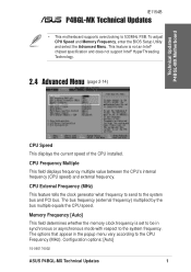
... to the CPU Frequency (MHz). Technical Updates P4BGL-MX Motherboard IE1154B P4BGL-MX Technical Updates • This motherboard supports overclocking to the system bus and PCI bus. CPU External Frequency (MHz) This feature tells the clock generator what frequency to send to 533MHz FSB. Configuration options: [Auto] 15-060174002 ASUS P4BGL-MX Technical Updates 1 CPU Frequency Multiple This field...
... to the CPU Frequency (MHz). Technical Updates P4BGL-MX Motherboard IE1154B P4BGL-MX Technical Updates • This motherboard supports overclocking to the system bus and PCI bus. CPU External Frequency (MHz) This feature tells the clock generator what frequency to send to 533MHz FSB. Configuration options: [Auto] 15-060174002 ASUS P4BGL-MX Technical Updates 1 CPU Frequency Multiple This field...

P4BGL-MX/533 User Manual
Page 1
Motherboard P4BGL-MX User Guide
Motherboard P4BGL-MX User Guide
P4BGL-MX/533 User Manual
Page 3
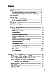
... 1-2 1.2 Package contents 1-2 1.3 Introduction 1-3 1.4 Motherboard components 1-3 1.5 Motherboard layout 1-6 1.6 Before you proceed 1-7 1.7 Central Processing Unit (CPU 1-7 1.8 System memory 1-8 1.9 Expansion Slots 1-9 1.9.1 Configuring an expansion card 1-9 1.9.2 Standard ...BIOS Setup Program 2-7 2.2.1 BIOS menu bar 2-7 2.2.2 Legend bar 2-8 iii BIOS Information 2-1 2.1 Managing and updating your BIOS 2-2 2.1.1 Using ASUS EZ FLASH to update the BIOS 2-2 2.1.2 Using ASUS AFLASH to find more information vii ASUS contact information vii Specifications summary ix Chapter 1 -
... 1-2 1.2 Package contents 1-2 1.3 Introduction 1-3 1.4 Motherboard components 1-3 1.5 Motherboard layout 1-6 1.6 Before you proceed 1-7 1.7 Central Processing Unit (CPU 1-7 1.8 System memory 1-8 1.9 Expansion Slots 1-9 1.9.1 Configuring an expansion card 1-9 1.9.2 Standard ...BIOS Setup Program 2-7 2.2.1 BIOS menu bar 2-7 2.2.2 Legend bar 2-8 iii BIOS Information 2-1 2.1 Managing and updating your BIOS 2-2 2.1.1 Using ASUS EZ FLASH to update the BIOS 2-2 2.1.2 Using ASUS AFLASH to find more information vii ASUS contact information vii Specifications summary ix Chapter 1 -
P4BGL-MX/533 User Manual
Page 6
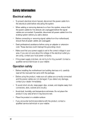
Operation safety • Before installing the motherboard and adding devices on a stable surface. • If you detect any area where it by yourself. Contact a qualified service technician or your dealer immediately. • ... area. If you are not sure about the voltage of the electrical outlet you add a device. • Before connecting or removing signal cables from the motherboard, ensure that came with the product, contact a qualified service technician or your local power company. • If the power supply is set to the correct...
Operation safety • Before installing the motherboard and adding devices on a stable surface. • If you detect any area where it by yourself. Contact a qualified service technician or your dealer immediately. • ... area. If you are not sure about the voltage of the electrical outlet you add a device. • Before connecting or removing signal cables from the motherboard, ensure that came with the product, contact a qualified service technician or your local power company. • If the power supply is set to the correct...
P4BGL-MX/533 User Manual
Page 11
Chapter 1 This chapter gives information about the ASUS P4BGL-MX motherboard that came with the system.This chapter includes the motherboard layout, jumper settings, and connector locations. Motherboard Info ASUS P4BGL-MX Motherboard 1-1
Chapter 1 This chapter gives information about the ASUS P4BGL-MX motherboard that came with the system.This chapter includes the motherboard layout, jumper settings, and connector locations. Motherboard Info ASUS P4BGL-MX Motherboard 1-1
P4BGL-MX/533 User Manual
Page 12
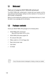
... damaged or missing, contact your package with new features and the most advanced technologies making it another standout in ASUS P4BGL-MX series support CD 40-conductor IDE cable Ribbon cable for buying the ASUS® P4BGL-MX motherboard! Before you for a 3.5-inch floppy drive Bag of extra jumper caps User Guide I/O Shield If any of the...
... damaged or missing, contact your package with new features and the most advanced technologies making it another standout in ASUS P4BGL-MX series support CD 40-conductor IDE cable Ribbon cable for buying the ASUS® P4BGL-MX motherboard! Before you for a 3.5-inch floppy drive Bag of extra jumper caps User Guide I/O Shield If any of the...
P4BGL-MX/533 User Manual
Page 13
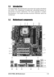
This motherboard is yet another high-quality motherboard from ASUS. 1.3 Introduction The ASUS P4BGL-MX motherboard is loaded with value-added features for guaranteed consumer satisfaction. For future upgrades or system reconfiguration, this chapter provides technical information about the motherboard. 1.4 Motherboard components 1 23 4 56 7 8 14 13 12 15 16 25 24 23 22 ASUS P4BGL-MX Motherboard 9 10 11 17 18 19 20 21 1-3
This motherboard is yet another high-quality motherboard from ASUS. 1.3 Introduction The ASUS P4BGL-MX motherboard is loaded with value-added features for guaranteed consumer satisfaction. For future upgrades or system reconfiguration, this chapter provides technical information about the motherboard. 1.4 Motherboard components 1 23 4 56 7 8 14 13 12 15 16 25 24 23 22 ASUS P4BGL-MX Motherboard 9 10 11 17 18 19 20 21 1-3
P4BGL-MX/533 User Manual
Page 14
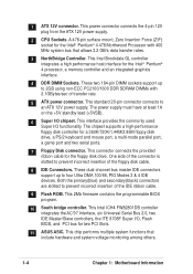
...functions that allows 3.2 GB/s data transfer rates. 3 NorthBridge Controller. This connector connects the provided ribbon cable for two PCI Slots. 11 ASUS ASIC. These dual-channel bus master IDE connectors support up to prevent incorrect insertion of the connector is slotted to 2GB using non-ECC PC2100.../1600 DDR SDRAM DIMMs with 400 MHz system bus that include hardware and system voltage monitoring among others. 1-4 Chapter 1: Motherboard Information This power connector connects the 4-pin 12V plug from the ATX 12V power supply. 2 CPU Sockets. 1 ATX 12V connector.
...functions that allows 3.2 GB/s data transfer rates. 3 NorthBridge Controller. This connector connects the provided ribbon cable for two PCI Slots. 11 ASUS ASIC. These dual-channel bus master IDE connectors support up to prevent incorrect insertion of the connector is slotted to 2GB using non-ECC PC2100.../1600 DDR SDRAM DIMMs with 400 MHz system bus that include hardware and system voltage monitoring among others. 1-4 Chapter 1: Motherboard Information This power connector connects the 4-pin 12V plug from the ATX 12V power supply. 2 CPU Sockets. 1 ATX 12V connector.
P4BGL-MX/533 User Manual
Page 15
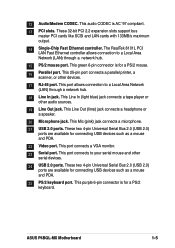
... (light blue) jack connects a tape player or other devices. 17 RJ-45 port. This Line Out (lime) jack connects a headphone or a speaker. 20 Microphone jack. ASUS P4BGL-MX Motherboard 1-5 12 Audio/Modem CODEC. This audio CODEC is for a PS/2 keyboard. These two 4-pin Universal Serial Bus 2.0 (USB 2.0) ports are available for connecting USB devices...
... (light blue) jack connects a tape player or other devices. 17 RJ-45 port. This Line Out (lime) jack connects a headphone or a speaker. 20 Microphone jack. ASUS P4BGL-MX Motherboard 1-5 12 Audio/Modem CODEC. This audio CODEC is for a PS/2 keyboard. These two 4-pin Universal Serial Bus 2.0 (USB 2.0) ports are available for connecting USB devices...
P4BGL-MX/533 User Manual
Page 16
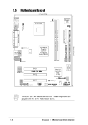
24.4cm (9.6in) 1.5 Motherboard layout 21.9cm (8.6in) PS/2KBMS T: Mouse B: Keyboard Bottom: USB20-3 USB20-4 COM1 Socket 478 CPUFAN1 Super I/O IR1 ATX Power Connector FLOPPY1 DDR DIMM1 (64/72 ... Hub (GMCH) 01 23 SEC_IDE PRI_ IDE RTL8101L ASPDIF1 PCI1 P4BGL-MX PCI2 Intel I/O Controller Hub (ICH4) ASUS Mozart Audio PCI3 Codec CD1 AUX1 CHASFAN1 COM2 USB20_5 USB20_6 BAT1 USBPWR_56 BUZZ1 CHASSIS1 J1 GAME1 ASUS PANEL1 The audio and LAN features are grayed out in the above motherboard layout. 1-6 Chapter 1: Motherboard Information These components are optional.
24.4cm (9.6in) 1.5 Motherboard layout 21.9cm (8.6in) PS/2KBMS T: Mouse B: Keyboard Bottom: USB20-3 USB20-4 COM1 Socket 478 CPUFAN1 Super I/O IR1 ATX Power Connector FLOPPY1 DDR DIMM1 (64/72 ... Hub (GMCH) 01 23 SEC_IDE PRI_ IDE RTL8101L ASPDIF1 PCI1 P4BGL-MX PCI2 Intel I/O Controller Hub (ICH4) ASUS Mozart Audio PCI3 Codec CD1 AUX1 CHASFAN1 COM2 USB20_5 USB20_6 BAT1 USBPWR_56 BUZZ1 CHASSIS1 J1 GAME1 ASUS PANEL1 The audio and LAN features are grayed out in the above motherboard layout. 1-6 Chapter 1: Motherboard Information These components are optional.
P4BGL-MX/533 User Manual
Page 17
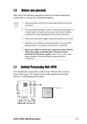
...came with a surface mount 478-pin Zero Insertion Force (ZIF) socket. Unplug the power cord from the power supply. P4BGL-MX P4BGL-MX Socket 478 Gold Arrow ASUS P4BGL-MX Motherboard 1-7 Before you install or remove any component, place it on them due to avoid touching the ICs on a grounded...specifically designed for the Intel® Pentium® 4 478/Northwood Processor. This socket is detached from the wall socket before touching any motherboard settings. 1. Use a grounded wrist strap or touch a safely grounded object or to a metal object, such as the power supply ...
...came with a surface mount 478-pin Zero Insertion Force (ZIF) socket. Unplug the power cord from the power supply. P4BGL-MX P4BGL-MX Socket 478 Gold Arrow ASUS P4BGL-MX Motherboard 1-7 Before you install or remove any component, place it on them due to avoid touching the ICs on a grounded...specifically designed for the Intel® Pentium® 4 478/Northwood Processor. This socket is detached from the wall socket before touching any motherboard settings. 1. Use a grounded wrist strap or touch a safely grounded object or to a metal object, such as the power supply ...
P4BGL-MX/533 User Manual
Page 18
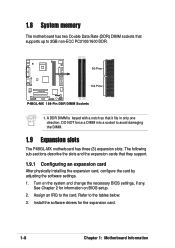
...sockets that supports up to the card. See Chapter 2 for the expansion card. 1-8 Chapter 1: Motherboard Information Assign an IRQ to 2GB non-ECC PC2100/1600 DDR. 80 Pins P4BGL-MX 104 Pins P4BGL-MX 184-Pin DDR DIMM Sockets 1. DO NOT force a DIMM into a socket to the tables below.... the expansion card, configure the card by adjusting the software settings. 1. Refer to avoid damaging the DIMM. 1.9 Expansion slots The P4BGL-MX motherboard has three (3) expansion slots. Turn on BIOS setup. 2. Install the software drivers for information on the system and change the necessary...
...sockets that supports up to the card. See Chapter 2 for the expansion card. 1-8 Chapter 1: Motherboard Information Assign an IRQ to 2GB non-ECC PC2100/1600 DDR. 80 Pins P4BGL-MX 104 Pins P4BGL-MX 184-Pin DDR DIMM Sockets 1. DO NOT force a DIMM into a socket to the tables below.... the expansion card, configure the card by adjusting the software settings. 1. Refer to avoid damaging the DIMM. 1.9 Expansion slots The P4BGL-MX motherboard has three (3) expansion slots. Turn on BIOS setup. 2. Install the software drivers for information on the system and change the necessary...
P4BGL-MX/533 User Manual
Page 19
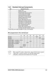
PCI slot 2 - - - - - - Onboard USB 1.1 controller 3 - - used - - shared - - - - - - ASUS P4BGL-MX Motherboard 1-9 used - - - - - used - - - - Onboard Audio - used - shared - - - - - - IRQ assignments for ISA or PCI devices. 1.9.2 Standard... Port 13 Numeric Data Processor 14 Primary IDE controller (dual fifo) 15 Secondary Ultra ATA Controller (dual fifo) *These IRQs are usually available for this motherboard A B C D E F G H PCI slot 1 - - - - - PCI slot 3 shared Onboard USB 1.1 controller 1 shared Onboard USB 1.1 controller 2 - - - ...
PCI slot 2 - - - - - - Onboard USB 1.1 controller 3 - - used - - shared - - - - - - ASUS P4BGL-MX Motherboard 1-9 used - - - - - used - - - - Onboard Audio - used - shared - - - - - - IRQ assignments for ISA or PCI devices. 1.9.2 Standard... Port 13 Numeric Data Processor 14 Primary IDE controller (dual fifo) 15 Secondary Ultra ATA Controller (dual fifo) *These IRQs are usually available for this motherboard A B C D E F G H PCI slot 1 - - - - - PCI slot 3 shared Onboard USB 1.1 controller 1 shared Onboard USB 1.1 controller 2 - - - ...
P4BGL-MX/533 User Manual
Page 20
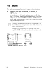
...jumpers are set to +5VSB. Set to +5VSB to wake up . P4BGL-MX USBPWR_34 3 2 2 1 +5V (Default) +5VSB USBPWR_12 USBPWR_56 12 23 +5V P4BGL-MX USB Device Wake Up (Default) +5VSB 1-10 Chapter 1: Motherboard Information This feature requires a power supply that can provide at least 1A... on the motherboard. 1. Otherwise, the system does not power up from S1 sleep mode...
...jumpers are set to +5VSB. Set to +5VSB to wake up . P4BGL-MX USBPWR_34 3 2 2 1 +5V (Default) +5VSB USBPWR_12 USBPWR_56 12 23 +5V P4BGL-MX USB Device Wake Up (Default) +5VSB 1-10 Chapter 1: Motherboard Information This feature requires a power supply that can provide at least 1A... on the motherboard. 1. Otherwise, the system does not power up from S1 sleep mode...
P4BGL-MX/533 User Manual
Page 21
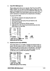
...CMOS. Keyboard power (3-pin KBPWR1) This jumper allows you press a key on the +5VSB lead, and a corresponding setting in the BIOS. P4BGL-MX KBPWR1 2 1 +5V (Default) 3 2 +5VSB (Default) P4BGL-MX Keyboard Power Setting ASUS P4BGL-MX Motherboard 1-11 Hold down the key during the boot process and enter BIOS setup to wake up feature. Plug the power cord...and unplug the power cord. 2. Clear RTC RAM (3-pin J1) These solder points allow you wish to re-enter data. To erase the RTC RAM: 1. P4BGL-MX P4BGL-MX Clear RTC RAM J1 12 23 Normal (Default) Clear CMOS 3. 2.
...CMOS. Keyboard power (3-pin KBPWR1) This jumper allows you press a key on the +5VSB lead, and a corresponding setting in the BIOS. P4BGL-MX KBPWR1 2 1 +5V (Default) 3 2 +5VSB (Default) P4BGL-MX Keyboard Power Setting ASUS P4BGL-MX Motherboard 1-11 Hold down the key during the boot process and enter BIOS setup to wake up feature. Plug the power cord...and unplug the power cord. 2. Clear RTC RAM (3-pin J1) These solder points allow you wish to re-enter data. To erase the RTC RAM: 1. P4BGL-MX P4BGL-MX Clear RTC RAM J1 12 23 Normal (Default) Clear CMOS 3. 2.
P4BGL-MX/533 User Manual
Page 22
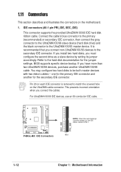
... hole on the IDE ribbon cable to the secondary IDE connector. P4BGL-MX P4BGL-MX IDE Connectors SEC_IDE PRI_IDE NOTE: Orient the red markings (usually zigzag) on the UltraDMA cable connector. PIN 1 1-12 Chapter 1: Motherboard Information IDE connectors (40-1 pin PRI_IDE, SEC_IDE) This connector supports...another for the jumper settings. If you connect the cables. 1.11 Connectors This section describes and illustrates the connectors on the motherboard. 1. For UltraDMA100/66 IDE devices, use an 80-conductor IDE cable. BIOS supports specific device bootup. one for the primary...
... hole on the IDE ribbon cable to the secondary IDE connector. P4BGL-MX P4BGL-MX IDE Connectors SEC_IDE PRI_IDE NOTE: Orient the red markings (usually zigzag) on the UltraDMA cable connector. PIN 1 1-12 Chapter 1: Motherboard Information IDE connectors (40-1 pin PRI_IDE, SEC_IDE) This connector supports...another for the jumper settings. If you connect the cables. 1.11 Connectors This section describes and illustrates the connectors on the motherboard. 1. For UltraDMA100/66 IDE devices, use an 80-conductor IDE cable. BIOS supports specific device bootup. one for the primary...

P4BGL-MX/533 User Manual
Page 23
... with intrusion detection feature. By default, the pins labeled "Chassis Signal" and "GND" are shorted with pin 5 plug). CHASSIS1 +5VSB_MB Chassis Signal GND P4BGL-MX P4BGL-MX Chassis Alarm Lead ASUS P4BGL-MX Motherboard 1-13 Chassis Alarm (4-1 pin CHASSIS1) This lead is removed to PIN 1. Floppy disk drive connector (34-1 pin FLOPPY1) This connector supports the provided floppy...
... with intrusion detection feature. By default, the pins labeled "Chassis Signal" and "GND" are shorted with pin 5 plug). CHASSIS1 +5VSB_MB Chassis Signal GND P4BGL-MX P4BGL-MX Chassis Alarm Lead ASUS P4BGL-MX Motherboard 1-13 Chassis Alarm (4-1 pin CHASSIS1) This lead is removed to PIN 1. Floppy disk drive connector (34-1 pin FLOPPY1) This connector supports the provided floppy...
P4BGL-MX/533 User Manual
Page 24
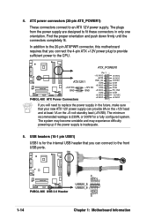
... provide sufficient power to the CPU. USB+5V LDM5 LDP5 GND NC P4BGL-MX P4BGL-MX USB 2.0 Header USB20_5 USB20_6 1 USB+5V LDM6 LDP6 GND 1-14 Chapter 1: Motherboard Information In addition to the 20-pin ATXPWR connector, this motherboard requires that you can provide 8A on the +12V lead and at ...power supply are designed to an ATX 12V power supply. ATX_POWER1 Pin 1 +12.0VDC +5VSB ATX12V1 PWR_OK COM P4BGL-MX +12V DC GND +12V DC GND +5.0VDC COM +5.0VDC COM +3.3VDC P4BGL-MX ATX Power Connectors +3.3VDC +5.0VDC +5.0VDC -5.0VDC COM COM COM PS_ON# COM -12.0VDC +3.3VDC If you...
... provide sufficient power to the CPU. USB+5V LDM5 LDP5 GND NC P4BGL-MX P4BGL-MX USB 2.0 Header USB20_5 USB20_6 1 USB+5V LDM6 LDP6 GND 1-14 Chapter 1: Motherboard Information In addition to the 20-pin ATXPWR connector, this motherboard requires that you can provide 8A on the +12V lead and at ...power supply are designed to an ATX 12V power supply. ATX_POWER1 Pin 1 +12.0VDC +5VSB ATX12V1 PWR_OK COM P4BGL-MX +12V DC GND +12V DC GND +5.0VDC COM +5.0VDC COM +3.3VDC P4BGL-MX ATX Power Connectors +3.3VDC +5.0VDC +5.0VDC -5.0VDC COM COM COM PS_ON# COM -12.0VDC +3.3VDC If you...
P4BGL-MX/533 User Manual
Page 25
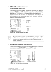
...These are not jumpers! Left Audio Channel Ground Ground Right Audio Channel Left Audio Channel Ground Ground Right Audio Channel P4BGL-MX CD1(Black) AUX1(White) P4BGL-MX Internal Audio Connectors ASUS P4BGL-MX Motherboard 1-15 Lack of sufficient air flow within the system may vary depending on the fan connectors! 7. DO NOT...stereo audio input from sound sources such as a CD-ROM, TV tuner, or MPEG card. CPUFAN1 GND +12V Rotation P4BGL-MX CHASFAN1 Rotation +12V GND P4BGL-MX 12-Volt Cooling Fan Power Do not forget to connect the fan cables to the ground pin. CPU and Chassis Fan ...
...These are not jumpers! Left Audio Channel Ground Ground Right Audio Channel Left Audio Channel Ground Ground Right Audio Channel P4BGL-MX CD1(Black) AUX1(White) P4BGL-MX Internal Audio Connectors ASUS P4BGL-MX Motherboard 1-15 Lack of sufficient air flow within the system may vary depending on the fan connectors! 7. DO NOT...stereo audio input from sound sources such as a CD-ROM, TV tuner, or MPEG card. CPUFAN1 GND +12V Rotation P4BGL-MX CHASFAN1 Rotation +12V GND P4BGL-MX 12-Volt Cooling Fan Power Do not forget to connect the fan cables to the ground pin. CPU and Chassis Fan ...
P4BGL-MX/533 User Manual
Page 26
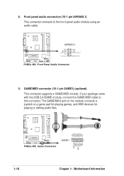
... playing games, and MIDI devices for playing or editing audio files. +5V J1B2 J1CY GND GND J1CX J1B1 +5V P4BGL-MX P4BGL-MX Game Connector GAME1 MIDI_IN J2B2 J2CY MIDI_OUT J2CX J2B1 +5V 1-16 Chapter 1: Motherboard Information Front panel audio connectors (10-1 pin IAPANEL1) This connector connects to this connector. If your package came with...
... playing games, and MIDI devices for playing or editing audio files. +5V J1B2 J1CY GND GND J1CX J1B1 +5V P4BGL-MX P4BGL-MX Game Connector GAME1 MIDI_IN J2B2 J2CY MIDI_OUT J2CX J2B1 +5V 1-16 Chapter 1: Motherboard Information Front panel audio connectors (10-1 pin IAPANEL1) This connector connects to this connector. If your package came with...


