Motherboard DIY Troubleshooting Guide
Page 1
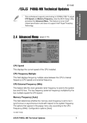
... CPU's internal frequency (CPU speed) and external frequency. The options that appear in synchronous or asynchronous mode with respect to the CPU Frequency (MHz). Memory Frequency [Auto] This field determines whether the memory clock frequency is not an Intel® chipset specification and does not support Intel® HyperThreading Technology. 2.4 Advanced Menu (page 2-14) CPU Speed This displays the current speed of the CPU installed. Technical Updates P4BGL-MX Motherboard IE1154B P4BGL-MX Technical Updates • This motherboard supports overclocking to the system bus and PCI bus...
... CPU's internal frequency (CPU speed) and external frequency. The options that appear in synchronous or asynchronous mode with respect to the CPU Frequency (MHz). Memory Frequency [Auto] This field determines whether the memory clock frequency is not an Intel® chipset specification and does not support Intel® HyperThreading Technology. 2.4 Advanced Menu (page 2-14) CPU Speed This displays the current speed of the CPU installed. Technical Updates P4BGL-MX Motherboard IE1154B P4BGL-MX Technical Updates • This motherboard supports overclocking to the system bus and PCI bus...
P4BGL-MX/533 User Manual
Page 14
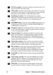
... insertion of the floppy disk cable. 8 IDE Connectors. The power supply must have at least 1A on the +5V standby lead (+5VSB). 6 Super I /O, Flash BIOS, and PCI bus for the floppy disk drive. This interface provides the commonly used Super I/O functionality. These dual-channel bus master IDE connectors support up to an ATX 12V power supply. This power connector connects the 4-pin 12V plug from the ATX 12V power supply. 2 CPU Sockets. This connector connects the provided ribbon cable for two PCI Slots. 11 ASUS ASIC. This chip performs multiple system...
... insertion of the floppy disk cable. 8 IDE Connectors. The power supply must have at least 1A on the +5V standby lead (+5VSB). 6 Super I /O, Flash BIOS, and PCI bus for the floppy disk drive. This interface provides the commonly used Super I/O functionality. These dual-channel bus master IDE connectors support up to an ATX 12V power supply. This power connector connects the 4-pin 12V plug from the ATX 12V power supply. 2 CPU Sockets. This connector connects the provided ribbon cable for two PCI Slots. 11 ASUS ASIC. This chip performs multiple system...
P4BGL-MX/533 User Manual
Page 15
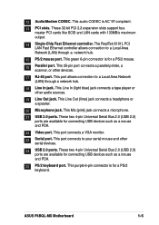
... other serial devices. 24 USB 2.0 ports. This purple 6-pin connector is AC '97 compliant. 13 PCI slots. These two 4-pin Universal Serial Bus 2.0 (USB 2.0) ports are available for connecting USB devices such as a mouse and PDA. 22 Video port. 12 Audio/Modem CODEC. These two 4-pin Universal Serial Bus 2.0 (USB 2.0) ports are available for connecting USB devices such as a mouse and PDA. 25 PS/2 keyboard port. ASUS P4BGL-MX Motherboard 1-5 These 32-bit PCI 2.2 expansion slots support bus master PCI cards like SCSI and LAN cards with 133MB/s maximum output. 14 Single-Chip...
... other serial devices. 24 USB 2.0 ports. This purple 6-pin connector is AC '97 compliant. 13 PCI slots. These two 4-pin Universal Serial Bus 2.0 (USB 2.0) ports are available for connecting USB devices such as a mouse and PDA. 22 Video port. 12 Audio/Modem CODEC. These two 4-pin Universal Serial Bus 2.0 (USB 2.0) ports are available for connecting USB devices such as a mouse and PDA. 25 PS/2 keyboard port. ASUS P4BGL-MX Motherboard 1-5 These 32-bit PCI 2.2 expansion slots support bus master PCI cards like SCSI and LAN cards with 133MB/s maximum output. 14 Single-Chip...
P4BGL-MX/533 User Manual
Page 18
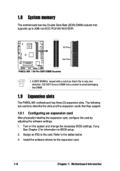
... P4BGL-MX motherboard has three (3) expansion slots. 1.8 System memory The motherboard has two Double Data Rate (DDR) DIMM sockets that supports up to the tables below. 3. Refer to 2GB non-ECC PC2100/1600 DDR. 80 Pins P4BGL-MX 104 Pins P4BGL-MX 184-Pin DDR DIMM Sockets 1. Turn on BIOS setup. 2. A DDR DIMM is keyed with a notch so that they support. 1.9.1 Configuring an expansion card After physically installing the expansion card, configure the card by adjusting the software settings...
... P4BGL-MX motherboard has three (3) expansion slots. 1.8 System memory The motherboard has two Double Data Rate (DDR) DIMM sockets that supports up to the tables below. 3. Refer to 2GB non-ECC PC2100/1600 DDR. 80 Pins P4BGL-MX 104 Pins P4BGL-MX 184-Pin DDR DIMM Sockets 1. Turn on BIOS setup. 2. A DDR DIMM is keyed with a notch so that they support. 1.9.1 Configuring an expansion card After physically installing the expansion card, configure the card by adjusting the software settings...
P4BGL-MX/533 User Manual
Page 19
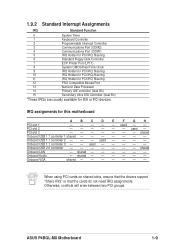
... Floppy Disk Controller 7 ECP Printer Port (LPT1) 8 System CMOS/Real Time Clock 9 IRQ Holder for PCI IRQ Steering 10 IRQ Holder for PCI IRQ Steering 11 IRQ Holder for PCI IRQ Steering 12 PS/2 Compatible Mouse Port 13 Numeric Data Processor 14 Primary IDE controller (dual fifo) 15 Secondary Ultra ATA Controller (dual fifo) *These IRQs are usually available for this motherboard A B C D E F G H PCI slot 1 - - - - - shared - - - - - - ASUS P4BGL-MX Motherboard 1-9 IRQ assignments for ISA or PCI devices. used - - Onboard Audio...
... Floppy Disk Controller 7 ECP Printer Port (LPT1) 8 System CMOS/Real Time Clock 9 IRQ Holder for PCI IRQ Steering 10 IRQ Holder for PCI IRQ Steering 11 IRQ Holder for PCI IRQ Steering 12 PS/2 Compatible Mouse Port 13 Numeric Data Processor 14 Primary IDE controller (dual fifo) 15 Secondary Ultra ATA Controller (dual fifo) *These IRQs are usually available for this motherboard A B C D E F G H PCI slot 1 - - - - - shared - - - - - - ASUS P4BGL-MX Motherboard 1-9 IRQ assignments for ISA or PCI devices. used - - Onboard Audio...
P4BGL-MX/533 User Manual
Page 21
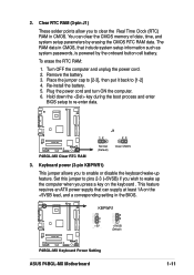
... down the key during the boot process and enter BIOS setup to [1-2] 4. 2. To erase the RTC RAM: 1. Re-install the battery. 5. This feature requires an ATX power supply that include system setup information such as system passwords, is powered by erasing the CMOS RTC RAM data. P4BGL-MX P4BGL-MX Clear RTC RAM J1 12 23 Normal (Default) Clear CMOS 3. P4BGL-MX KBPWR1 2 1 +5V (Default) 3 2 +5VSB (Default) P4BGL-MX Keyboard Power Setting ASUS P4BGL-MX Motherboard 1-11 Clear RTC RAM (3-pin J1) These solder points allow you to enable or disable the keyboard wake-up...
... down the key during the boot process and enter BIOS setup to [1-2] 4. 2. To erase the RTC RAM: 1. Re-install the battery. 5. This feature requires an ATX power supply that include system setup information such as system passwords, is powered by erasing the CMOS RTC RAM data. P4BGL-MX P4BGL-MX Clear RTC RAM J1 12 23 Normal (Default) Clear CMOS 3. P4BGL-MX KBPWR1 2 1 +5V (Default) 3 2 +5VSB (Default) P4BGL-MX Keyboard Power Setting ASUS P4BGL-MX Motherboard 1-11 Clear RTC RAM (3-pin J1) These solder points allow you to enable or disable the keyboard wake-up...
P4BGL-MX/533 User Manual
Page 22
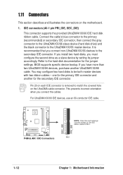
... IDE connector. Pin 20 on each IDE connector is recommended that you must configure the second drive as a slave device by setting its jumper accordingly. IDE connectors (40-1 pin PRI_IDE, SEC_IDE) This connector supports the provided UltraDMA100/66 IDE hard disk ribbon cable. PIN 1 1-12 Chapter 1: Motherboard Information It is removed to match the covered hole on the UltraDMA cable connector. For UltraDMA100/66 IDE devices, use an 80-conductor IDE cable. If you install two hard disks, you connect non-UltraDMA100/66 devices...
... IDE connector. Pin 20 on each IDE connector is recommended that you must configure the second drive as a slave device by setting its jumper accordingly. IDE connectors (40-1 pin PRI_IDE, SEC_IDE) This connector supports the provided UltraDMA100/66 IDE hard disk ribbon cable. PIN 1 1-12 Chapter 1: Motherboard Information It is removed to match the covered hole on the UltraDMA cable connector. For UltraDMA100/66 IDE devices, use an 80-conductor IDE cable. If you install two hard disks, you connect non-UltraDMA100/66 devices...
P4BGL-MX/533 User Manual
Page 28
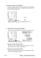
... P4BGL-MX Message LED SMI Lead Reset SW ATX Power Switch* P4BGL-MX System Panel Connectors * Requires an ATX power supply. • System Power LED Lead (2-pin PLED) This 2-pin connector connects to the primary or secondary IDE slots. The LED lights up on the system power. • Keyboard Lock Lead (2-pin KEYLOCK) This 2-pin connector connects to a chassis-mounted switch to allow the use of the disk drives connected to the system power LED. P4BGL-MX HDDLED TIP: If the case-mounted LED does not P4BGL-MX HDD Activity LED light, try reversing the 2-pin plug. 13. 12. Hard disk...
... P4BGL-MX Message LED SMI Lead Reset SW ATX Power Switch* P4BGL-MX System Panel Connectors * Requires an ATX power supply. • System Power LED Lead (2-pin PLED) This 2-pin connector connects to the primary or secondary IDE slots. The LED lights up on the system power. • Keyboard Lock Lead (2-pin KEYLOCK) This 2-pin connector connects to a chassis-mounted switch to allow the use of the disk drives connected to the system power LED. P4BGL-MX HDDLED TIP: If the case-mounted LED does not P4BGL-MX HDD Activity LED light, try reversing the 2-pin plug. 13. 12. Hard disk...
P4BGL-MX/533 User Manual
Page 32
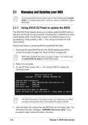
... motherboard's original BIOS to a bootable floppy disk in case you need to type the exact BIOS file name at the EZ Flash screen. 2. Device not ready." To use EZ Flash, press + during the Power-On Self Tests (POST). You will copy file from A:\, Press [ESC] to update the BIOS using a DOS-based utility. Reboot the computer. 3. Save the file to display the following screen. You need to reinstall the original BIOS later. 2.1.1 Using ASUS EZ Flash to update...
... motherboard's original BIOS to a bootable floppy disk in case you need to type the exact BIOS file name at the EZ Flash screen. 2. Device not ready." To use EZ Flash, press + during the Power-On Self Tests (POST). You will copy file from A:\, Press [ESC] to update the BIOS using a DOS-based utility. Reboot the computer. 3. Save the file to display the following screen. You need to reinstall the original BIOS later. 2.1.1 Using ASUS EZ Flash to update...
P4BGL-MX/533 User Manual
Page 35
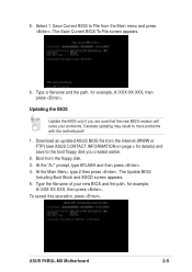
... Boot Block and ESCD screen appears. 5. To cancel this operation, press . Download an updated ASUS BIOS file from the Internet (WWW or FTP) (see ASUS CONTACT INFORMATION on page x for details) and save to the boot floppy disk you are sure that the new BIOS revision will solve your new BIOS and the path, for example, A:\XXX-XX.XXX, then press . ASUS P4BGL-MX Motherboard 2-5 At the Main Menu, type...
... Boot Block and ESCD screen appears. 5. To cancel this operation, press . Download an updated ASUS BIOS file from the Internet (WWW or FTP) (see ASUS CONTACT INFORMATION on page x for details) and save to the boot floppy disk you are sure that the new BIOS revision will solve your new BIOS and the path, for example, A:\XXX-XX.XXX, then press . ASUS P4BGL-MX Motherboard 2-5 At the Main Menu, type...
P4BGL-MX/533 User Manual
Page 37
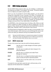
... following BIOS setup screens and descriptions are installing a motherboard, reconfiguring your system, or prompted to configure your computer in the CMOS RAM of the EEPROM. This requires you with its test routines. ADVANCED Use this menu to configure the default system device used to the power management settings. This section explains how to "Run Setup". BOOT Use this menu to enable and make changes to locate and load the Operating System. Because the BIOS software is...
... following BIOS setup screens and descriptions are installing a motherboard, reconfiguring your system, or prompted to configure your computer in the CMOS RAM of the EEPROM. This requires you with its test routines. ADVANCED Use this menu to configure the default system device used to the power management settings. This section explains how to "Run Setup". BOOT Use this menu to enable and make changes to locate and load the Operating System. Because the BIOS software is...
P4BGL-MX/533 User Manual
Page 42
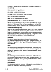
... removing a drive and not replacing it, select [None]. for IDE magneto optical disk drives [Other ATAPI Device] - for LS-120 compatible floppy disk drives [ZIP] - To make changes to this field, set the Type field to [User Type HDD] and the Translation Method field to determine the correct value. Refer to the drive documentation to [Manual]. for the hard disk drive that LBA Mode is necessary for cylinders, heads, or sectors. When the Main menu...
... removing a drive and not replacing it, select [None]. for IDE magneto optical disk drives [Other ATAPI Device] - for LS-120 compatible floppy disk drives [ZIP] - To make changes to this field, set the Type field to [User Type HDD] and the Translation Method field to determine the correct value. Refer to the drive documentation to [Manual]. for the hard disk drive that LBA Mode is necessary for cylinders, heads, or sectors. When the Main menu...

P4BGL-MX/533 User Manual
Page 43
... you entered. You may decrease system performance. Configuration options: [Disabled] [Enabled] PIO Mode [4] This option lets you set a PIO (Programmed Input/Output) mode for compatible IDE devices. Modes 0 through 4 provide successive increase in the SMART monitoring feature may also manually configure this field is normally disabled because the resources used in performance. Refer to this field, set it manually. Set to [Disabled] to [User Type HDD]. Configuration options: [0] [1] [2] [3] [4] [5] [Disabled] 2.3.2 Keyboard Features ASUS P4BGL-MX Motherboard 2-13...
... you entered. You may decrease system performance. Configuration options: [Disabled] [Enabled] PIO Mode [4] This option lets you set a PIO (Programmed Input/Output) mode for compatible IDE devices. Modes 0 through 4 provide successive increase in the SMART monitoring feature may also manually configure this field is normally disabled because the resources used in performance. Refer to this field, set it manually. Set to [Disabled] to [User Type HDD]. Configuration options: [0] [1] [2] [3] [4] [5] [Disabled] 2.3.2 Keyboard Features ASUS P4BGL-MX Motherboard 2-13...

P4BGL-MX/533 User Manual
Page 44
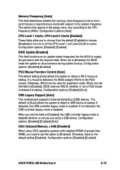
... field enables users to the system bus and PCI bus. Configuration options: [Off] [On] Keyboard Auto-Repeat Rate [6/Sec] This controls the speed at which the system registers repeated keystrokes. To adjust CPU Speed and Memory Frequency, enter the BIOS Setup Utility and select the Advanced Menu. CPU Speed This displays the current speed of the CPU installed. CPU External Frequency (MHz) This feature tells the clock generator what frequency to send to activate the Number Lock function upon system boot. Options...
... field enables users to the system bus and PCI bus. Configuration options: [Off] [On] Keyboard Auto-Repeat Rate [6/Sec] This controls the speed at which the system registers repeated keystrokes. To adjust CPU Speed and Memory Frequency, enter the BIOS Setup Utility and select the Advanced Menu. CPU Speed This displays the current speed of the CPU installed. CPU External Frequency (MHz) This feature tells the clock generator what frequency to send to activate the Number Lock function upon system boot. Options...
P4BGL-MX/533 User Manual
Page 45
... Frequency [Auto] This field determines whether the memory clock frequency is set to be used for expansion cards. Configuration options: [Disabled] [Enabled] [Auto] OS/2 Onboard Memory > 64M [Disabled] When using a USB device. If detected, the USB controller legacy mode is disabled. Configuration options: [Auto] CPU Level 1 Cache, CPU Level 2 Cache [Enabled] These fields allow you set this field to [Enabled], BIOS reserves IRQ12, whether or not a PS/2 mouse is detected, the BIOS assigns IRQ12 to the PS/2 mouse. Configuration options: [Disabled] [Enabled] ASUS P4BGL-MX Motherboard...
... Frequency [Auto] This field determines whether the memory clock frequency is set to be used for expansion cards. Configuration options: [Disabled] [Enabled] [Auto] OS/2 Onboard Memory > 64M [Disabled] When using a USB device. If detected, the USB controller legacy mode is disabled. Configuration options: [Auto] CPU Level 1 Cache, CPU Level 2 Cache [Enabled] These fields allow you set this field to [Enabled], BIOS reserves IRQ12, whether or not a PS/2 mouse is detected, the BIOS assigns IRQ12 to the PS/2 mouse. Configuration options: [Disabled] [Enabled] ASUS P4BGL-MX Motherboard...
P4BGL-MX/533 User Manual
Page 47
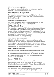
... feature frees the PCI bus when the CPU is accessing 8-bit ISA cards. Configuration options: [Both] [Primary] [Secondary] [Disabled] USB 2.0 HS Reference Voltage [Medium] This item controls the USB 2.0 high-speed drive strength reference voltage. Configuration options: [128MB] [256MB] AGP Capability [4X Mode] This motherboard supports the AGP 4x interface that are using ISA cards that transfers video data at 1066MB/s. Configuration options: [1X Mode] [4X Mode] Video Memory Cache Mode [UC] USWC (uncacheable, speculative write combining) is backward-compatible, so you may not boot...
... feature frees the PCI bus when the CPU is accessing 8-bit ISA cards. Configuration options: [Both] [Primary] [Secondary] [Disabled] USB 2.0 HS Reference Voltage [Medium] This item controls the USB 2.0 high-speed drive strength reference voltage. Configuration options: [128MB] [256MB] AGP Capability [4X Mode] This motherboard supports the AGP 4x interface that are using ISA cards that transfers video data at 1066MB/s. Configuration options: [1X Mode] [4X Mode] Video Memory Cache Mode [UC] USWC (uncacheable, speculative write combining) is backward-compatible, so you may not boot...
P4BGL-MX/533 User Manual
Page 49
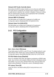
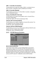
...[Auto], which utilizes auto-routing to determine IRQ assignments. ASUS P4BGL-MX Motherboard 2-19 If there are conflicts with the onboard audio controller, set the appropriate field to [Enabled] corrects this problem. Configuration options: [Disabled] [Enabled] PCI Latency Timer [32] Leave this field to the default setting [Disabled]. if no audio device is detected, the controller is enabled; Configuration options: [Auto] [NA] [3] [4] [5] [7] [9] [10] [11] [12] [14] [15] PCI/VGA Palette Snoop [Disabled] Some non-standard VGA cards, like graphics accelerators or MPEG video...
...[Auto], which utilizes auto-routing to determine IRQ assignments. ASUS P4BGL-MX Motherboard 2-19 If there are conflicts with the onboard audio controller, set the appropriate field to [Enabled] corrects this problem. Configuration options: [Disabled] [Enabled] PCI Latency Timer [32] Leave this field to the default setting [Disabled]. if no audio device is detected, the controller is enabled; Configuration options: [Auto] [NA] [3] [4] [5] [7] [9] [10] [11] [12] [14] [15] PCI/VGA Palette Snoop [Disabled] Some non-standard VGA cards, like graphics accelerators or MPEG video...
P4BGL-MX/533 User Manual
Page 50
...Set the IRQ field to turn on or off the onboard LAN boot ROM.This item appears only when onboard LAN is being used by a legacy ISA card. Configuration options: [Disabled] [Enabled] Primary VGA BIOS [PCI VGA Card] This field allows you to enable or disable the onboard LAN controller. Configuration options: [Disabled] [Enabled] Onboard LAN Boot ROM [Disabled] This field allows you to activate. Configuration options: [PCI VGA Card] [Onboard VGA] Onboard LAN Controller [Enabled] This field allows you to select primary graphics card or onboard VGA as the primary display BIOS. USB...
...Set the IRQ field to turn on or off the onboard LAN boot ROM.This item appears only when onboard LAN is being used by a legacy ISA card. Configuration options: [Disabled] [Enabled] Primary VGA BIOS [PCI VGA Card] This field allows you to enable or disable the onboard LAN controller. Configuration options: [Disabled] [Enabled] Onboard LAN Boot ROM [Disabled] This field allows you to activate. Configuration options: [PCI VGA Card] [Onboard VGA] Onboard LAN Controller [Enabled] This field allows you to select primary graphics card or onboard VGA as the primary display BIOS. USB...
P4BGL-MX/533 User Manual
Page 60
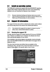
... your choice. 3-2 Chapter 3: Starting-Up Also, included is enabled in your computer, the software and drivers menu automatically appears on your OS documentation for technical support. Because motherboard settings and hardware options vary, use the setup procedures presented in the support CD to your screen. Refer to display the menu. If the installation menu did not appear automatically, locate and doubleclick on the specific option of the support CD are available...
... your choice. 3-2 Chapter 3: Starting-Up Also, included is enabled in your computer, the software and drivers menu automatically appears on your OS documentation for technical support. Because motherboard settings and hardware options vary, use the setup procedures presented in the support CD to your screen. Refer to display the menu. If the installation menu did not appear automatically, locate and doubleclick on the specific option of the support CD are available...
P4BGL-MX/533 User Manual
Page 61
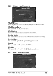
...menu ASUS PC Probe Install utility that can monitor Fan, Speed, Voltage, and CPU temperature. DirectX This item installs the Microsoft DirectX V8.1 driver. ASUS Update Installs utility to optimize 3D graphics output. PC-cillin This item installs the Trend PC-cillin 2002 anti-virus software. 3.2.3 Drivers installation menu ASUS P4BGL-MX Motherboard 3-3 E-Color 3Deep This item installs application to download and update motherboard BIOS. ASUS Screen Saver This item installs the ASUS screen saver. Acrobat Reader This installs software for viewing files in Portable Document Format (PDF...
...menu ASUS PC Probe Install utility that can monitor Fan, Speed, Voltage, and CPU temperature. DirectX This item installs the Microsoft DirectX V8.1 driver. ASUS Update Installs utility to optimize 3D graphics output. PC-cillin This item installs the Trend PC-cillin 2002 anti-virus software. 3.2.3 Drivers installation menu ASUS P4BGL-MX Motherboard 3-3 E-Color 3Deep This item installs application to download and update motherboard BIOS. ASUS Screen Saver This item installs the ASUS screen saver. Acrobat Reader This installs software for viewing files in Portable Document Format (PDF...


