Motherboard DIY Troubleshooting Guide
Page 1
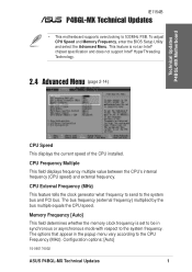
... CPU Speed and Memory Frequency, enter the BIOS Setup Utility and select the Advanced Menu. CPU External Frequency (MHz) This feature tells the clock generator what frequency to send to the CPU Frequency (MHz). Configuration options: [Auto] 15-060174002 ASUS P4BGL-MX Technical Updates 1 Technical Updates P4BGL-MX Motherboard IE1154B P4BGL-MX Technical Updates • This motherboard supports...
... CPU Speed and Memory Frequency, enter the BIOS Setup Utility and select the Advanced Menu. CPU External Frequency (MHz) This feature tells the clock generator what frequency to send to the CPU Frequency (MHz). Configuration options: [Auto] 15-060174002 ASUS P4BGL-MX Technical Updates 1 Technical Updates P4BGL-MX Motherboard IE1154B P4BGL-MX Technical Updates • This motherboard supports...
P4BGL-MX/533 User Manual
Page 3
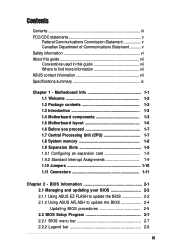
... information vi About this guide vii Conventions used in this guide vii Where to update the BIOS 2-4 Updating BIOS procedures 2-5 2.2 BIOS Setup Program 2-7 2.2.1 BIOS menu bar 2-7 2.2.2 Legend bar 2-8 iii BIOS Information 2-1 2.1 Managing and updating your BIOS 2-2 2.1.1 Using ASUS EZ FLASH to update the BIOS 2-2 2.1.2 Using ASUS AFLASH to find more information vii ASUS contact information vii Specifications summary ix Chapter 1 -
... information vi About this guide vii Conventions used in this guide vii Where to update the BIOS 2-4 Updating BIOS procedures 2-5 2.2 BIOS Setup Program 2-7 2.2.1 BIOS menu bar 2-7 2.2.2 Legend bar 2-8 iii BIOS Information 2-1 2.1 Managing and updating your BIOS 2-2 2.1.1 Using ASUS EZ FLASH to update the BIOS 2-2 2.1.2 Using ASUS AFLASH to find more information vii ASUS contact information vii Specifications summary ix Chapter 1 -
P4BGL-MX/533 User Manual
Page 9
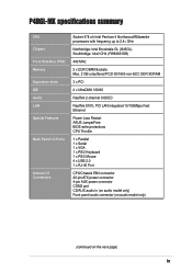
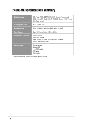
P4BGL-MX specifications summary CPU Chipset Front Side Bus (FSB) Memory Expansion slots IDE Audio LAN Special Features Back Panel I/O Ports Internal I/O Connectors Socket 478 ofr Intel ... PC2100/1600 non-ECC DDR SDRAM 3 x PCI 2 x UltraDMA 100/66 RealTek 2-channel CODEC RealTek 8101L PCI LAN integrated 10/100Mbps Fast Ethernet Power Loss Restart ASUS JumperFree BIOS write protections CPU Throttle 1 x Parallel 1 x Serial 1 x VGA 1 x PS/2 Keyboard 1 x PS/2 Mouse 4 x USB 2.0 1 x RJ-45 Port CPU/Chassis FAN connector 20 pin ATX power connector...
P4BGL-MX specifications summary CPU Chipset Front Side Bus (FSB) Memory Expansion slots IDE Audio LAN Special Features Back Panel I/O Ports Internal I/O Connectors Socket 478 ofr Intel ... PC2100/1600 non-ECC DDR SDRAM 3 x PCI 2 x UltraDMA 100/66 RealTek 2-channel CODEC RealTek 8101L PCI LAN integrated 10/100Mbps Fast Ethernet Power Loss Restart ASUS JumperFree BIOS write protections CPU Throttle 1 x Parallel 1 x Serial 1 x VGA 1 x PS/2 Keyboard 1 x PS/2 Mouse 4 x USB 2.0 1 x RJ-45 Port CPU/Chassis FAN connector 20 pin ATX power connector...
P4BGL-MX/533 User Manual
Page 10
x Manageability WfM2.0, DMI2.0, WOR by PME, WOL by BME Form Factor Micro-ATX form factor: 8.6 in x 9.6 in Support CD contents Device drivers ASUS PC Probe Trend Microtm PC-cillin 2002 anti-virus software ASUS LiveUpdate Utility Accessories User's manual Support CD 1 x USB Bracket IDE cable FDD cable * Specifications are subject to change without notice. P4BGL-MX specifications summary BIOS features 2Mb Flash ROM, EEPROM, ASUS JumperFree, Award BIOS with ACPI, DMI2.0, PnP, WfM2.0, Green, TCAV (Trend Chip Away Virus) Industry standard PCI 2.2, USB 2.0.
x Manageability WfM2.0, DMI2.0, WOR by PME, WOL by BME Form Factor Micro-ATX form factor: 8.6 in x 9.6 in Support CD contents Device drivers ASUS PC Probe Trend Microtm PC-cillin 2002 anti-virus software ASUS LiveUpdate Utility Accessories User's manual Support CD 1 x USB Bracket IDE cable FDD cable * Specifications are subject to change without notice. P4BGL-MX specifications summary BIOS features 2Mb Flash ROM, EEPROM, ASUS JumperFree, Award BIOS with ACPI, DMI2.0, PnP, WfM2.0, Green, TCAV (Trend Chip Away Virus) Industry standard PCI 2.2, USB 2.0.
P4BGL-MX/533 User Manual
Page 14
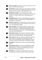
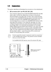
... Serial Bus 2.0, two IDE Master/Slave controllers, the ITE 8708F Super I/O, Flash BIOS, and PCI bus for the floppy disk drive. This connector connects the provided ribbon cable for two PCI Slots. 11 ASUS ASIC. Both the primary(blue) and secondary(black) connectors are slotted to 2GB using...Intel® Pentium® 4 478/Northwood Processor with 2.1GBytes/sec of the IDE ribbon cable. 9 Flash ROM. This 2Mb firmware contains the programmable BIOS program. 10 South bridge controller. This power connector connects the 4-pin 12V plug from the ATX 12V power supply. 2 CPU Sockets. A 478-...
... Serial Bus 2.0, two IDE Master/Slave controllers, the ITE 8708F Super I/O, Flash BIOS, and PCI bus for the floppy disk drive. This connector connects the provided ribbon cable for two PCI Slots. 11 ASUS ASIC. Both the primary(blue) and secondary(black) connectors are slotted to 2GB using...Intel® Pentium® 4 478/Northwood Processor with 2.1GBytes/sec of the IDE ribbon cable. 9 Flash ROM. This 2Mb firmware contains the programmable BIOS program. 10 South bridge controller. This power connector connects the 4-pin 12V plug from the ATX 12V power supply. 2 CPU Sockets. A 478-...
P4BGL-MX/533 User Manual
Page 18
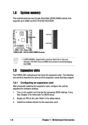
... information on the system and change the necessary BIOS settings, if any. The following sub-sections describe the slots and the expansion cards that it fits in only one direction. Refer to avoid damaging the DIMM. 1.9 Expansion slots The P4BGL-MX motherboard has three (3) expansion slots. Assign an... IRQ to 2GB non-ECC PC2100/1600 DDR. 80 Pins P4BGL-MX 104 Pins P4BGL-MX 184-Pin DDR DIMM Sockets 1. A DDR DIMM is keyed with a notch so ...
... information on the system and change the necessary BIOS settings, if any. The following sub-sections describe the slots and the expansion cards that it fits in only one direction. Refer to avoid damaging the DIMM. 1.9 Expansion slots The P4BGL-MX motherboard has three (3) expansion slots. Assign an... IRQ to 2GB non-ECC PC2100/1600 DDR. 80 Pins P4BGL-MX 104 Pins P4BGL-MX 184-Pin DDR DIMM Sockets 1. A DDR DIMM is keyed with a notch so ...
P4BGL-MX/533 User Manual
Page 21
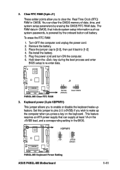
... enable or disable the keyboard wake-up the computer when you to clear the Real Time Clock (RTC) RAM in the BIOS. P4BGL-MX KBPWR1 2 1 +5V (Default) 3 2 +5VSB (Default) P4BGL-MX Keyboard Power Setting ASUS P4BGL-MX Motherboard 1-11 2. You can supply at least 1A on the keyboard . Re-install the battery. 5. Keyboard power (3-pin KBPWR1) This jumper... system passwords, is powered by erasing the CMOS RTC RAM data. Turn OFF the computer and unplug the power cord. 2. To erase the RTC RAM: 1. P4BGL-MX P4BGL-MX Clear RTC RAM J1 12 23 Normal (Default) Clear CMOS 3.
... enable or disable the keyboard wake-up the computer when you to clear the Real Time Clock (RTC) RAM in the BIOS. P4BGL-MX KBPWR1 2 1 +5V (Default) 3 2 +5VSB (Default) P4BGL-MX Keyboard Power Setting ASUS P4BGL-MX Motherboard 1-11 2. You can supply at least 1A on the keyboard . Re-install the battery. 5. Keyboard power (3-pin KBPWR1) This jumper... system passwords, is powered by erasing the CMOS RTC RAM data. Turn OFF the computer and unplug the power cord. 2. To erase the RTC RAM: 1. P4BGL-MX P4BGL-MX Clear RTC RAM J1 12 23 Normal (Default) Clear CMOS 3.
P4BGL-MX/533 User Manual
Page 22
Refer to the UltraDMA100/66 master device. P4BGL-MX P4BGL-MX IDE Connectors SEC_IDE PRI_IDE NOTE: Orient the red markings (usually zigzag) on the motherboard. 1. It is removed to match the covered hole on the UltraDMA ... the primary IDE connector and another UltraDMA100/66 cable. If you connect non-UltraDMA100/66 devices to be both master devices with two ribbon cables - BIOS supports specific device bootup. For UltraDMA100/66 IDE devices, use an 80-conductor IDE cable.
Refer to the UltraDMA100/66 master device. P4BGL-MX P4BGL-MX IDE Connectors SEC_IDE PRI_IDE NOTE: Orient the red markings (usually zigzag) on the motherboard. 1. It is removed to match the covered hole on the UltraDMA ... the primary IDE connector and another UltraDMA100/66 cable. If you connect non-UltraDMA100/66 devices to be both master devices with two ribbon cables - BIOS supports specific device bootup. For UltraDMA100/66 IDE devices, use an 80-conductor IDE cable.
P4BGL-MX/533 User Manual
Page 27
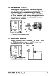
...View Back View SIR CIR IRTX +5V GND (NC) IRRX P4BGL-MX Infrared Module Connector 11. Serial connector (9-pin COM2 ) This 9-pin connector connects to the pin definitions. COM2 PIN 1 P4BGL-MX P4BGL-MX Serial COM2 Bracket ASUS P4BGL-MX Motherboard 1-17 Connect the COM2 cable to this feature. Use... the ten pins as shown in the rear panel of the chassis. The module mounts to set UART2 for use with IR. You must also configure the UART2 Use As parameter in BIOS...
...View Back View SIR CIR IRTX +5V GND (NC) IRRX P4BGL-MX Infrared Module Connector 11. Serial connector (9-pin COM2 ) This 9-pin connector connects to the pin definitions. COM2 PIN 1 P4BGL-MX P4BGL-MX Serial COM2 Bracket ASUS P4BGL-MX Motherboard 1-17 Connect the COM2 cable to this feature. Use... the ten pins as shown in the rear panel of the chassis. The module mounts to set UART2 for use with IR. You must also configure the UART2 Use As parameter in BIOS...
P4BGL-MX/533 User Manual
Page 29
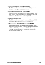
... BIOS or OS settings. Pressing the power switch while in which system activity is instantly decreased to save power and to expand the life of certain system components. • Reset Switch (2-pin RESET) This 2-pin connector connects to the case-mounted reset switch for more than 4 seconds turns the system OFF. ASUS P4BGL-MX...
... BIOS or OS settings. Pressing the power switch while in which system activity is instantly decreased to save power and to expand the life of certain system components. • Reset Switch (2-pin RESET) This 2-pin connector connects to the case-mounted reset switch for more than 4 seconds turns the system OFF. ASUS P4BGL-MX...
P4BGL-MX/533 User Manual
Page 31
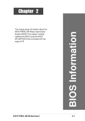
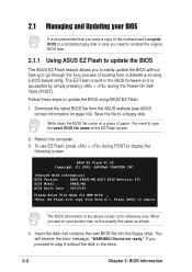
BIOS Information ASUS P4BGL-MX Motherboard 2-1 Chapter 2 This chapter gives information about the ASUS P4BGL-MX Binary Input/Output System (BIOS).This chapter includes updating the BIOS using the ASUS AFLASH BIOS that is bundled with the support CD.
BIOS Information ASUS P4BGL-MX Motherboard 2-1 Chapter 2 This chapter gives information about the ASUS P4BGL-MX Binary Input/Output System (BIOS).This chapter includes updating the BIOS using the ASUS AFLASH BIOS that is bundled with the support CD.
P4BGL-MX/533 User Manual
Page 32
... of paper. if you see ASUS contact information on page viii). Write down the BIOS file name on your BIOS It is recommended that contains the new BIOS file into the floppy drive. ASUS EZ Flash V1.00 Copyright (C) 2002, ASUSTeK COMPUTER INC. [Onboard BIOS Information] BIOS Version : ASUS P4BGL-MX ACPI BIOS Revision 001 BIOS Model : P4BGL-MX BIOS Built Date : 09/16/02...
... of paper. if you see ASUS contact information on page viii). Write down the BIOS file name on your BIOS It is recommended that contains the new BIOS file into the floppy drive. ASUS EZ Flash V1.00 Copyright (C) 2002, ASUSTeK COMPUTER INC. [Onboard BIOS Information] BIOS Version : ASUS P4BGL-MX ACPI BIOS Revision 001 BIOS Model : P4BGL-MX BIOS Built Date : 09/16/02...
P4BGL-MX/533 User Manual
Page 33
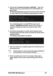
... Memory: SST 49LF004 1. Update Boot Block area (Y/N)? _ (Y/N)? _ 7. Press . 6. At the above prompt, type Y to update the BIOS (Y/N)? _ If you downloaded from the ASUS website, then press . Press Y for the file name that you accidentally typed in the correct file name. When the update process is done... name, the error message, "WARNING! DO NOT shutdown or reset the system while updating the BIOS boot block area! ASUS P4BGL-MX Motherboard 2-3 Press to reboot the system with the update process. EZ Flash will automatically access drive A to look for both items to ...
... Memory: SST 49LF004 1. Update Boot Block area (Y/N)? _ (Y/N)? _ 7. Press . 6. At the above prompt, type Y to update the BIOS (Y/N)? _ If you downloaded from the ASUS website, then press . Press Y for the file name that you accidentally typed in the correct file name. When the update process is done... name, the error message, "WARNING! DO NOT shutdown or reset the system while updating the BIOS boot block area! ASUS P4BGL-MX Motherboard 2-3 Press to reboot the system with the update process. EZ Flash will automatically access drive A to look for both items to ...

P4BGL-MX/533 User Manual
Page 34
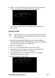
...memory chip is either not programmable or is your motherboard, check the last four numbers of the code displayed on the motherboard. BIOS setup must specify "Floppy" as shown. This file works only in DOS mode. What you boot from the floppy disk. Larger ...numbers represent a newer BIOS file. 1. 2.1.2 Using AFLASH to update the BIOS The BIOS information in the above screen is a Flash Memory Writer utility that updates the BIOS by the Flash Memory Writer utility. 2-4 Chapter 2: BIOS Information Type COPY D:\AFLASH\AFLASH.EXE A:\ (assuming D ...
...memory chip is either not programmable or is your motherboard, check the last four numbers of the code displayed on the motherboard. BIOS setup must specify "Floppy" as shown. This file works only in DOS mode. What you boot from the floppy disk. Larger ...numbers represent a newer BIOS file. 1. 2.1.2 Using AFLASH to update the BIOS The BIOS information in the above screen is a Flash Memory Writer utility that updates the BIOS by the Flash Memory Writer utility. 2-4 Chapter 2: BIOS Information Type COPY D:\AFLASH\AFLASH.EXE A:\ (assuming D ...
P4BGL-MX/533 User Manual
Page 35
...the boot floppy disk you are sure that the new BIOS revision will solve your new BIOS and the path, for example, A:\XXX-XX.XXX, then press . The Update BIOS Including Boot Block and ESCD screen appears. 5. ASUS P4BGL-MX Motherboard 2-5 At the "A:\" prompt, type AFLASH and ...then press . 4. To cancel this operation, press . Download an updated ASUS BIOS file from the floppy disk. 3. Type a filename and ...
...the boot floppy disk you are sure that the new BIOS revision will solve your new BIOS and the path, for example, A:\XXX-XX.XXX, then press . The Update BIOS Including Boot Block and ESCD screen appears. 5. ASUS P4BGL-MX Motherboard 2-5 At the "A:\" prompt, type AFLASH and ...then press . 4. To cancel this operation, press . Download an updated ASUS BIOS file from the floppy disk. 3. Type a filename and ...
P4BGL-MX/533 User Manual
Page 36
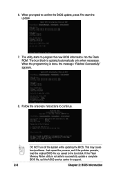
...start the update. 7. 6. When prompted to confirm the BIOS update, press Y to continue. If the Flash Memory Writer utility is done, the message "Flashed Successfully" appears. 8. DO NOT turn off the system while updating the BIOS. The utility starts to the boot disk. When the ...programming is not able to successfully update a complete BIOS file, call the ASUS service center for support. 2-6 Chapter 2: BIOS Information The boot block is updated automatically only when necessary. This may cause boot problems. Just repeat the process...
...start the update. 7. 6. When prompted to confirm the BIOS update, press Y to continue. If the Flash Memory Writer utility is done, the message "Flashed Successfully" appears. 8. DO NOT turn off the system while updating the BIOS. The utility starts to the boot disk. When the ...programming is not able to successfully update a complete BIOS file, call the ASUS service center for support. 2-6 Chapter 2: BIOS Information The boot block is updated automatically only when necessary. This may cause boot problems. Just repeat the process...
P4BGL-MX/533 User Manual
Page 37
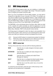
... your system using the BIOS Setup program so that the computer can scroll through the various submenus and make changes to the advanced features. BOOT Use this menu to enable and make your selections among the predetermined choices. ASUS P4BGL-MX Motherboard 2-7 ADVANCED Use ...this menu to configure the default system device used to locate and load the Operating System. For example, you see on your screen. 2.2.1 BIOS menu bar The top of the EEPROM. ...
... your system using the BIOS Setup program so that the computer can scroll through the various submenus and make changes to the advanced features. BOOT Use this menu to enable and make your selections among the predetermined choices. ASUS P4BGL-MX Motherboard 2-7 ADVANCED Use ...this menu to configure the default system device used to locate and load the Operating System. For example, you see on your screen. 2.2.1 BIOS menu bar The top of the EEPROM. ...
P4BGL-MX/533 User Manual
Page 38
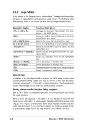
...to its Setup Defaults Saves changes and exits Setup General help window, press or . 2-8 Chapter 2: BIOS Information To exit the help In addition to the Item Specific Help window, the BIOS setup program also provides a General Help screen. The following table lists the keys found in the ...legend bar with their corresponding functions. Navigation Key(s) Function Description or Displays the General Help screen from anywhere in the BIOS Setup Jumps to the Exit menu or returns to the main menu from any menu by simply pressing or the + combination. 2.2.2 Legend...
...to its Setup Defaults Saves changes and exits Setup General help window, press or . 2-8 Chapter 2: BIOS Information To exit the help In addition to the Item Specific Help window, the BIOS setup program also provides a General Help screen. The following table lists the keys found in the ...legend bar with their corresponding functions. Navigation Key(s) Function Description or Displays the General Help screen from anywhere in the BIOS Setup Jumps to the Exit menu or returns to the main menu from any menu by simply pressing or the + combination. 2.2.2 Legend...
P4BGL-MX/533 User Manual
Page 40
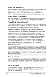
... password is set a password, highlight the appropriate field and press . Forgot the password? Re-install the battery after about passwords The BIOS Setup program allows you did not set to [Enabled]. If you to specify two different passwords: a Supervisor password and a User password.... To set to [Disabled]. This password allows full access to the BIOS during system startup. Press . The format is required to support older Japanese floppy drives. To confirm the password, type the password again...
... password is set a password, highlight the appropriate field and press . Forgot the password? Re-install the battery after about passwords The BIOS Setup program allows you did not set to [Enabled]. If you to specify two different passwords: a Supervisor password and a User password.... To set to [Disabled]. This password allows full access to the BIOS during system startup. Press . The format is required to support older Japanese floppy drives. To confirm the password, type the password again...
P4BGL-MX/533 User Manual
Page 42
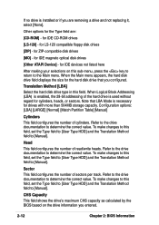
... This field configures the number of cylinders. Sector This field configures the number of the hard drive is installed or if you entered. 2-12 Chapter 2: BIOS Information for IDE magneto optical disk drives [Other ATAPI Device] - Refer to the drive documentation to determine the correct value. To make changes to this... (LBA) is enabled, the 28-bit addressing of sectors per track. CHS Capacity This field shows the drive's maximum CHS capacity as calculated by the BIOS based on this field.
... This field configures the number of cylinders. Sector This field configures the number of the hard drive is installed or if you entered. 2-12 Chapter 2: BIOS Information for IDE magneto optical disk drives [Other ATAPI Device] - Refer to the drive documentation to determine the correct value. To make changes to this... (LBA) is enabled, the 28-bit addressing of sectors per track. CHS Capacity This field shows the drive's maximum CHS capacity as calculated by the BIOS based on this field.


