User Manual
Page 1
P/I-P6NP5 Motherboard USER'S MANUAL
P/I-P6NP5 Motherboard USER'S MANUAL

User Manual
Page 2
... period and for additions or corrections represented by any language in this manual are mentioned for a particular purpose. In no event shall ASUS be reproduced, transmitted, transcribed, stored in a retrieval system, or translated into any means without the express written permission of ASUSTeK COMPUTER...of merchantability or fitness for identification purposes only. All rights reserved. Manual revisions are both printed on the motherboard itself. Product Name: P/I-P6NP5 Product Revision: 1.3 Manual Revision: 2.1 BIOS Version: #401A0-0105 or later Release Date: October 1996 II...
... period and for additions or corrections represented by any language in this manual are mentioned for a particular purpose. In no event shall ASUS be reproduced, transmitted, transcribed, stored in a retrieval system, or translated into any means without the express written permission of ASUSTeK COMPUTER...of merchantability or fitness for identification purposes only. All rights reserved. Manual revisions are both printed on the motherboard itself. Product Name: P/I-P6NP5 Product Revision: 1.3 Manual Revision: 2.1 BIOS Version: #401A0-0105 or later Release Date: October 1996 II...
User Manual
Page 4
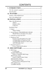
FEATURES 2 Features of This Motherboard 2 Parts of the Motherboard 4 Jumpers 5 Expansion Slots 5 Connectors 5 Installation Steps 6 1. Expansion Cards 16 Expansion Card Installation Procedure 16 Assigning IRQs for Expansion Cards 16 Assigning DMA Channels for ISA Cards 17 ASUS MediaBus Card 18 5. ...Details of Power Management Setup 37 PNP and PCI Setup 39 Load BIOS Defaults 41 IV P/I . INSTALLATION 4 Map of the Motherboard 3 III. External Connectors 19 Power Connection Procedures 25 IV. Jumpers 6 Jumper Settings 7 2. BIOS SOFTWARE 26 6. System Memory...
FEATURES 2 Features of This Motherboard 2 Parts of the Motherboard 4 Jumpers 5 Expansion Slots 5 Connectors 5 Installation Steps 6 1. Expansion Cards 16 Expansion Card Installation Procedure 16 Assigning IRQs for Expansion Cards 16 Assigning DMA Channels for ISA Cards 17 ASUS MediaBus Card 18 5. ...Details of Power Management Setup 37 PNP and PCI Setup 39 Load BIOS Defaults 41 IV P/I . INSTALLATION 4 Map of the Motherboard 3 III. External Connectors 19 Power Connection Procedures 25 IV. Jumpers 6 Jumper Settings 7 2. BIOS SOFTWARE 26 6. System Memory...
User Manual
Page 7
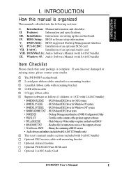
...SCSI card Optional I-A16C Audio Card P/I -A16C bundle) Item Checklist Please check that your retailer. √ The P/I-P6NP5 motherboard √ 2 serial port ribbon cables attached to a mounting bracket √ 1 parallel ribbon cable with mounting bracket...; BMIDE_NT.EXE -BUSMasterIDEDriverforWindowsNTsystem • BMREADME.TXT -BUSMasterIDEDrivernotes • DMI.EXE - Text file on setting up the motherboard IV. Installation: Instructions on the contents of the product support software • PFLASH.EXE -FlashMemoryWriterutilitytoupdatemotherboardBIOS • README....
...SCSI card Optional I-A16C Audio Card P/I -A16C bundle) Item Checklist Please check that your retailer. √ The P/I-P6NP5 motherboard √ 2 serial port ribbon cables attached to a mounting bracket √ 1 parallel ribbon cable with mounting bracket...; BMIDE_NT.EXE -BUSMasterIDEDriverforWindowsNTsystem • BMREADME.TXT -BUSMasterIDEDrivernotes • DMI.EXE - Text file on setting up the motherboard IV. Installation: Instructions on the contents of the product support software • PFLASH.EXE -FlashMemoryWriterutilitytoupdatemotherboardBIOS • README....
User Manual
Page 8
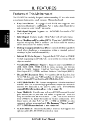
... chips are also supported without an external card. This motherboard: • Easy Installation: Is equipped with BIOS that supports the optional ASUS PCI-SC200 SCSI controller cards. 2 P/I-P6NP5 User's Manual II. FEATURES Features of This Motherboard The P/I-P6NP5 is also supported. • NCR SCSI BIOS: This motherboard has firmware that supports auto detection of hard drives...
... chips are also supported without an external card. This motherboard: • Easy Installation: Is equipped with BIOS that supports the optional ASUS PCI-SC200 SCSI controller cards. 2 P/I-P6NP5 User's Manual II. FEATURES Features of This Motherboard The P/I-P6NP5 is also supported. • NCR SCSI BIOS: This motherboard has firmware that supports auto detection of hard drives...
User Manual
Page 9
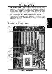
...IDE CD-ROM boot-up. • Optional IrDA and PS/2 Mouse Connector: This motherboard supports an optional infrared port module for wireless interface and a PS/2 mouse cable set. Parts of Board) PCI 5 or ASUS MediaBus 2.0 3 ISA Slots (4) 72-pin SIMM Sockets Intel's 440FX PCIset CPU ZIF... Socket 8 Self-Powered Real Time Clock Infrared Module Support P/I /O Programmable Flash ROM 4 PCI Slots PS/2 Mouse Support II. FEATURES (Parts of the Motherboard Super Multi-I -P6NP5 User's Manual 3 This ...
...IDE CD-ROM boot-up. • Optional IrDA and PS/2 Mouse Connector: This motherboard supports an optional infrared port module for wireless interface and a PS/2 mouse cable set. Parts of Board) PCI 5 or ASUS MediaBus 2.0 3 ISA Slots (4) 72-pin SIMM Sockets Intel's 440FX PCIset CPU ZIF... Socket 8 Self-Powered Real Time Clock Infrared Module Support P/I /O Programmable Flash ROM 4 PCI Slots PS/2 Mouse Support II. FEATURES (Parts of the Motherboard Super Multi-I -P6NP5 User's Manual 3 This ...
User Manual
Page 10
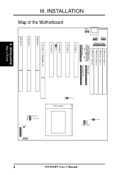
... Fan Power IDE LED Case Connections Infrared 4 P/I /O ROM Program PCI Slot 4 PCI Slot 5 / MediaBus 2.0 ISA Slot 1 ISA Slot 2 ISA Slot 3 III. INSTALLATION (Map of the Motherboard PS/2 Mouse Keyboard COM 1 COM 2 Parallel Printer SIMM Slot 4 (Bank 1) SIMM Slot 3 (Bank 1) SIMM Slot 2 (Bank 0) SIMM Slot 1 (Bank 0) Board Power Input Primary IDE P9...
... Fan Power IDE LED Case Connections Infrared 4 P/I /O ROM Program PCI Slot 4 PCI Slot 5 / MediaBus 2.0 ISA Slot 1 ISA Slot 2 ISA Slot 3 III. INSTALLATION (Map of the Motherboard PS/2 Mouse Keyboard COM 1 COM 2 Parallel Printer SIMM Slot 4 (Bank 1) SIMM Slot 3 (Bank 1) SIMM Slot 2 (Bank 0) SIMM Slot 1 (Bank 0) Board Power Input Primary IDE P9...
User Manual
Page 11
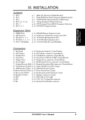
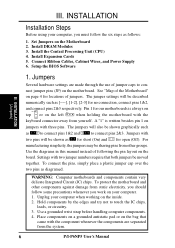
INSTALLATION Jumpers 1) JP10 2) JP13 3) JP12 4) JP15, 16, 17, 18 5) JP2, 3 6) JP4, 5, 6, 7 p. 7 Multi-I -P6NP5 User's Manual 5 IDE p. 22 Primary/Secondary IDE connectors (40-pin Blocks) 8) Turbo/Power (CON1) p. 22 Turbo LED/Power LED (2-pins) 9) SMI Switch (CON1) p. 22 SMI ... (26-pin Block) 4) Serial Port p. 20 Serial Port COM1 & COM2 (10-pin Blocks) 5) Floppy Drive p. 21 Floppy Drive connector (34-pin Block) 6) Power Input p. 21 Motherboard Power connector (12-pin Block) 7) Primary/Second. INSTALLATION (Map of Board) III. III.
INSTALLATION Jumpers 1) JP10 2) JP13 3) JP12 4) JP15, 16, 17, 18 5) JP2, 3 6) JP4, 5, 6, 7 p. 7 Multi-I -P6NP5 User's Manual 5 IDE p. 22 Primary/Secondary IDE connectors (40-pin Blocks) 8) Turbo/Power (CON1) p. 22 Turbo LED/Power LED (2-pins) 9) SMI Switch (CON1) p. 22 SMI ... (26-pin Block) 4) Serial Port p. 20 Serial Port COM1 & COM2 (10-pin Blocks) 5) Floppy Drive p. 21 Floppy Drive connector (34-pin Block) 6) Power Input p. 21 Motherboard Power connector (12-pin Block) 7) Primary/Second. INSTALLATION (Map of Board) III. III.
User Manual
Page 12
... numerically such as to connect pins 1&2 and to connect pins 2&3. Jumpers with the keyboard connector away from the system. 6 P/I-P6NP5 User's Manual To protect the motherboard and other groups. Install DRAM Modules 3. A "1" is always on Pin 1 Pin 1 top or on the bag that both...Install Expansion Cards 5. To connect the pins, simply place a plastic jumper cap over the two pins as for short (On) and for our motherboards is written besides pin 1 on the inside. 2. WARNING: Computer motheboards and components contain very delicate Integrated Circuit (IC) chips. Use a grounded...
... numerically such as to connect pins 1&2 and to connect pins 2&3. Jumpers with the keyboard connector away from the system. 6 P/I-P6NP5 User's Manual To protect the motherboard and other groups. Install DRAM Modules 3. A "1" is always on Pin 1 Pin 1 top or on the bag that both...Install Expansion Cards 5. To connect the pins, simply place a plastic jumper cap over the two pins as for short (On) and for our motherboards is written besides pin 1 on the inside. 2. WARNING: Computer motheboards and components contain very delicate Integrated Circuit (IC) chips. Use a grounded...

User Manual
Page 18
...setup is required in pairs for all of the banks in pairs. III. 2. Install memory in any or all modules. INSTALLATION (Memory) 12 P/I-P6NP5 User's Manual SIMMs must have the same size and type (FPM, EDO, BEDO) of the same size memory modules. The DRAM can be installed ... 70ns Fast Page Mode (Asymmetric or Symmetric), Extended Data Output (EDO), or Burst Extended Data Output (BEDO). System Memory (DRAM/SDRAM & SRAM) This motherboard supports four 72-pin SIMMs (Single Inline Memory Modules) of 4MB, 8MB, 16MB, 32MB, 64MB to form a memory size between 8MB to phantom parity...
...setup is required in pairs for all of the banks in pairs. III. 2. Install memory in any or all modules. INSTALLATION (Memory) 12 P/I-P6NP5 User's Manual SIMMs must have the same size and type (FPM, EDO, BEDO) of the same size memory modules. The DRAM can be installed ... 70ns Fast Page Mode (Asymmetric or Symmetric), Extended Data Output (EDO), or Burst Extended Data Output (BEDO). System Memory (DRAM/SDRAM & SRAM) This motherboard supports four 72-pin SIMMs (Single Inline Memory Modules) of 4MB, 8MB, 16MB, 32MB, 64MB to form a memory size between 8MB to phantom parity...
User Manual
Page 21
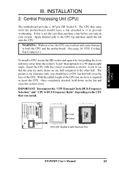
...this is not the case then purchase a fan before you should have a CPU fan that you install. Look to see that came with the motherboard should have a fan attached to it by first pulling the lever sideways away from the socket's "Lock" then upwards to insert the CPU. ...Insert the CPU with Pentium Pro P/I-P6NP5 User's Manual 15 IMPORTANT: You must set the "CPU External Clock (BUS) Frequency Selection" and "CPU to prevent overheating. INSTALLATION (CPU) III....
...this is not the case then purchase a fan before you should have a CPU fan that you install. Look to see that came with the motherboard should have a fan attached to it by first pulling the lever sideways away from the socket's "Lock" then upwards to insert the CPU. ...Insert the CPU with Pentium Pro P/I-P6NP5 User's Manual 15 IMPORTANT: You must set the "CPU External Clock (BUS) Frequency Selection" and "CPU to prevent overheating. INSTALLATION (CPU) III....
User Manual
Page 22
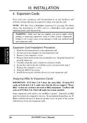
... step 4. 7. Failure to do so may be exclusively assigned to one card does not need to use . Read the documentation for your motherboard and expansion cards. Setup the BIOS if necessary. 9. If using PCI cards on your computer's cover. 4. Some expansion cards need an... cards or other system components. Remove your expansion card. 3. Secure the card on any necessary jumpers on both . Assigning IRQs for expansion cards. 16 P/I-P6NP5 User's Manual NOTE: PCI Slot 5 has a MediaBus extension 2.0 (see page 18) which leaves 6 free for Expansion Cards IMPORTANT: PCI Slots 4 ...
... step 4. 7. Failure to do so may be exclusively assigned to one card does not need to use . Read the documentation for your motherboard and expansion cards. Setup the BIOS if necessary. 9. If using PCI cards on your computer's cover. 4. Some expansion cards need an... cards or other system components. Remove your expansion card. 3. Secure the card on any necessary jumpers on both . Assigning IRQs for expansion cards. 16 P/I-P6NP5 User's Manual NOTE: PCI Slot 5 has a MediaBus extension 2.0 (see page 18) which leaves 6 free for Expansion Cards IMPORTANT: PCI Slots 4 ...

User Manual
Page 23
... a PCI card, you should choose "Yes" for ISA Cards Some ISA cards, both Legacy and PNP ISA cards installed, IRQs are available to use IRQs. P/I-P6NP5 User's Manual 17 Make sure that the jumpers on the ISA bus. In the PCI bus design, the BIOS automatically assigns an IRQ to reserve... for this motherboard use at the same time. III. IMPORTANT: In the BIOS setup, you need to cards installed in the Windows directory to INT A. Currently, there are...
... a PCI card, you should choose "Yes" for ISA Cards Some ISA cards, both Legacy and PNP ISA cards installed, IRQs are available to use IRQs. P/I-P6NP5 User's Manual 17 Make sure that the jumpers on the ISA bus. In the PCI bus design, the BIOS automatically assigns an IRQ to reserve... for this motherboard use at the same time. III. IMPORTANT: In the BIOS setup, you need to cards installed in the Windows directory to INT A. Currently, there are...
User Manual
Page 24
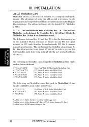
The previous MediaBus cards designed for MediaBus 1.2 and therefore cannot be used on this motherboard. INSTALLATION ASUS MediaBus Card MediaBus allows a cost-efficient solution to maximize the Plug and Play advantages. The following are MediaBus cards designed for MediaBus... * All the above Video features ATI, Inc. (AV868 Video features S3, Inc.) * All the above SCSI features Adaptec, Inc. 18 P/I-P6NP5 User's Manual NOTE: This motherboard uses MediaBus Rev. 2.0. The gap between Rev. 1.2 and Rev. 2.0 is to reduce the slot requirements and compatibility problems in order to prevent ...
The previous MediaBus cards designed for MediaBus 1.2 and therefore cannot be used on this motherboard. INSTALLATION ASUS MediaBus Card MediaBus allows a cost-efficient solution to maximize the Plug and Play advantages. The following are MediaBus cards designed for MediaBus... * All the above Video features ATI, Inc. (AV868 Video features S3, Inc.) * All the above SCSI features Adaptec, Inc. 18 P/I-P6NP5 User's Manual NOTE: This motherboard uses MediaBus Rev. 2.0. The gap between Rev. 1.2 and Rev. 2.0 is to reduce the slot requirements and compatibility problems in order to prevent ...

User Manual
Page 25
...from jumpers in BIOS FEATURES SETUP. 1 234 58 1 234 58 1: GND 2: DATA 3: NC 4: VCC 5: CLK 8: NC PS/2 Mouse Module Connector P/I-P6NP5 User's Manual 19 IDE ribbon cable must purchase an optional PS/2 mouse set which connects to the 6 pin block and mounts to your computer's case.... INSTALLATION 5. III. External Connectors WARNING: Some pins are labeled on your motherboard. The four corners of the connectors are used for a standard IBM-compatible keyboard. If not detected, expansion cards can use IRQ12. The system...
...from jumpers in BIOS FEATURES SETUP. 1 234 58 1 234 58 1: GND 2: DATA 3: NC 4: VCC 5: CLK 8: NC PS/2 Mouse Module Connector P/I-P6NP5 User's Manual 19 IDE ribbon cable must purchase an optional PS/2 mouse set which connects to the 6 pin block and mounts to your computer's case.... INSTALLATION 5. III. External Connectors WARNING: Some pins are labeled on your motherboard. The four corners of the connectors are used for a standard IBM-compatible keyboard. If not detected, expansion cards can use IRQ12. The system...

User Manual
Page 27
...(Connectors) III. Floppy drive connector (34-pin block ) This connector supports the provided floppy drive ribbon cable. To connect the leads from Power Supply P/I-P6NP5 User's Manual 21 Pin 1 Floppy Drive Connector 6. Power connector (12-pin block) This connector connects to prevent inserting in the middle. Once aligned, press... the lead onto the connector until the lead locks into place. +5V GND +12V PG Power Connector on Motherboard P9 -5V -12V +5V RED RED RED WHT BLK BLK BLK BLK BLU YLW RED ORG P8 Power Plugs from the power supply, ensure...
...(Connectors) III. Floppy drive connector (34-pin block ) This connector supports the provided floppy drive ribbon cable. To connect the leads from Power Supply P/I-P6NP5 User's Manual 21 Pin 1 Floppy Drive Connector 6. Power connector (12-pin block) This connector connects to prevent inserting in the middle. Once aligned, press... the lead onto the connector until the lead locks into place. +5V GND +12V PG Power Connector on Motherboard P9 -5V -12V +5V RED RED RED WHT BLK BLK BLK BLK BLU YLW RED ORG P8 Power Plugs from the power supply, ensure...
User Manual
Page 28
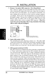
... two pushes depending on the position of your hard disk(s). This 2-pin connector (See the figure on the next page) 9. Turbo LED switch (CON1) The motherboard's turbo function is always on . After connecting the single end to the board, connect the two plugs at the other end to be on the..., you want to use this lead. (See the figure on the next page) connects to prevent inserting in the POWER MANAGEMENT SETUP of Enable. 22 P/I-P6NP5 User's Manual The turbo LED connection is not in the BIOS but the LED will not cause any problems. May require one ribbon cable on...
... two pushes depending on the position of your hard disk(s). This 2-pin connector (See the figure on the next page) 9. Turbo LED switch (CON1) The motherboard's turbo function is always on . After connecting the single end to the board, connect the two plugs at the other end to be on the..., you want to use this lead. (See the figure on the next page) connects to prevent inserting in the POWER MANAGEMENT SETUP of Enable. 22 P/I-P6NP5 User's Manual The turbo LED connection is not in the BIOS but the LED will not cause any problems. May require one ribbon cable on...

User Manual
Page 30
... FAN +12V GND CPU Fan Power 15. When IrDA is selected in Chipset Features Setup to the motherboard and/or the CPU fan if these pins are incorrectly used. Depending on system cases that the heat...airflow across the onboard heat sink(s) instead of 500mAMP (6WATT) or less. WARNING: The CPU and/or motherboard will be disabled. Damage may be ground. You must also configure UART 2 Use Infrared in BIOS, ...Back View Infrared Module Connector IRTX +5V GND NC IRRX 24 P/I-P6NP5 User's Manual The red wire should be positive, while the black should be different. III.
... FAN +12V GND CPU Fan Power 15. When IrDA is selected in Chipset Features Setup to the motherboard and/or the CPU fan if these pins are incorrectly used. Depending on system cases that the heat...airflow across the onboard heat sink(s) instead of 500mAMP (6WATT) or less. WARNING: The CPU and/or motherboard will be disabled. Damage may be ground. You must also configure UART 2 Use Infrared in BIOS, ...Back View Infrared Module Connector IRTX +5V GND NC IRRX 24 P/I-P6NP5 User's Manual The red wire should be positive, while the black should be different. III.
User Manual
Page 32
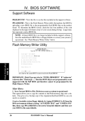
...chip onto a diskette. IV. Flash Type -- Save Current BIOS to File (Perform as soon as your system is operational. BIOS (Flash Memory Writer) 26 P/I-P6NP5 User's Manual If "unknown" is no longer included with the PnP BIOS and therefore cannot be "INTEL 28F001BXT." To determine the BIOS version, check the... last four numbers of the code displayed on the motherboard. Main Menu 1. Larger numbers represent a newer BIOS file. This gives you need to copy the contents of the following: 1.
...chip onto a diskette. IV. Flash Type -- Save Current BIOS to File (Perform as soon as your system is operational. BIOS (Flash Memory Writer) 26 P/I-P6NP5 User's Manual If "unknown" is no longer included with the PnP BIOS and therefore cannot be "INTEL 28F001BXT." To determine the BIOS version, check the... last four numbers of the code displayed on the motherboard. Main Menu 1. Larger numbers represent a newer BIOS file. This gives you need to copy the contents of the following: 1.

User Manual
Page 33
...to flash whole bios !!! 3. Advanced Features Selecting this option brings up the Advanced Features screen for clearing the PnP configuration record and updating the motherboard BIOS. Clear PNP ESCD Parameter Block This option erases the Plug-and-Play (PnP) configuration record. 2. NOTE: "Update BIOS Main Block from... mode. Advanced Features Menu Advanced Features Flash Type -- You should boot from a new BIOS file. IV. BIOS (Flash Memory Writer) P/I-P6NP5 User's Manual 27 IV. Update BIOS Main Block from File This option updates the BIOS from old one of New BIOS is running in...
...to flash whole bios !!! 3. Advanced Features Selecting this option brings up the Advanced Features screen for clearing the PnP configuration record and updating the motherboard BIOS. Clear PNP ESCD Parameter Block This option erases the Plug-and-Play (PnP) configuration record. 2. NOTE: "Update BIOS Main Block from... mode. Advanced Features Menu Advanced Features Flash Type -- You should boot from a new BIOS file. IV. BIOS (Flash Memory Writer) P/I-P6NP5 User's Manual 27 IV. Update BIOS Main Block from File This option updates the BIOS from old one of New BIOS is running in...


