User Manual
Page 1
P/I-P6NP5 Motherboard USER'S MANUAL
P/I-P6NP5 Motherboard USER'S MANUAL

User Manual
Page 2
...'s home page at: http://www.asus.com.tw/ Products mentioned in this manual are mentioned for a particular purpose. Manual revisions are both printed on the motherboard itself. Product Name: P/I-P6NP5 Product Revision: 1.3 Manual Revision: 2.1 BIOS Version: #401A0-0105 or later Release Date: October 1996 II P/I-P6NP5 User's Manual ASUS may revise this manual from any defect or error in...
...'s home page at: http://www.asus.com.tw/ Products mentioned in this manual are mentioned for a particular purpose. Manual revisions are both printed on the motherboard itself. Product Name: P/I-P6NP5 Product Revision: 1.3 Manual Revision: 2.1 BIOS Version: #401A0-0105 or later Release Date: October 1996 II P/I-P6NP5 User's Manual ASUS may revise this manual from any defect or error in...
User Manual
Page 4
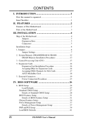
...26 6. Expansion Cards 16 Expansion Card Installation Procedure 16 Assigning IRQs for Expansion Cards 16 Assigning DMA Channels for ISA Cards 17 ASUS MediaBus Card 18 5. BIOS Setup 26 Load Defaults 27 Standard CMOS Setup 27 Details of Standard CMOS Setup 28 BIOS Features Setup...34 Power Management Setup 37 Details of Power Management Setup 37 PNP and PCI Setup 39 Load BIOS Defaults 41 IV P/I . INTRODUCTION 1 How this manual is organized 1 Item Checklist 1 II. INSTALLATION 4 Map of the Motherboard 3 III. System Memory (DRAM/SDRAM & SRAM 12 DRAM Memory Installation ...
...26 6. Expansion Cards 16 Expansion Card Installation Procedure 16 Assigning IRQs for Expansion Cards 16 Assigning DMA Channels for ISA Cards 17 ASUS MediaBus Card 18 5. BIOS Setup 26 Load Defaults 27 Standard CMOS Setup 27 Details of Standard CMOS Setup 28 BIOS Features Setup...34 Power Management Setup 37 Details of Power Management Setup 37 PNP and PCI Setup 39 Load BIOS Defaults 41 IV P/I . INTRODUCTION 1 How this manual is organized 1 Item Checklist 1 II. INSTALLATION 4 Map of the Motherboard 3 III. System Memory (DRAM/SDRAM & SRAM 12 DRAM Memory Installation ...
User Manual
Page 5
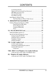
... 50 VI. I-A16C Audio Card 57 I -A16C Audio Card Bundle Only) IX. DOS 3.1 & Windows 3.1x Audio Software (with optional I-A16C Audio Card Bundle Only) P/I-P6NP5 User's Manual V Windows 95 Audio Software (with optional I -A16C Audio Features 57 Unpacking and Handling Precautions 57 Layout and Connectors 58 Connectors 58 VIII. CONTENTS Load Setup...
... 50 VI. I-A16C Audio Card 57 I -A16C Audio Card Bundle Only) IX. DOS 3.1 & Windows 3.1x Audio Software (with optional I-A16C Audio Card Bundle Only) P/I-P6NP5 User's Manual V Windows 95 Audio Software (with optional I -A16C Audio Features 57 Unpacking and Handling Precautions 57 Layout and Connectors 58 Connectors 58 VIII. CONTENTS Load Setup...
User Manual
Page 6
... connected. • Consult the dealer or an experienced radio/TV technician for radio noise emissions from that interference will not occur in a residential installation. VI P/I-P6NP5 User's Manual WARNING: The use of shielded cables for a Class B digital device, pursuant to Part 15 of the following two conditions: • This device may not...
... connected. • Consult the dealer or an experienced radio/TV technician for radio noise emissions from that interference will not occur in a residential installation. VI P/I-P6NP5 User's Manual WARNING: The use of shielded cables for a Class B digital device, pursuant to Part 15 of the following two conditions: • This device may not...
User Manual
Page 7
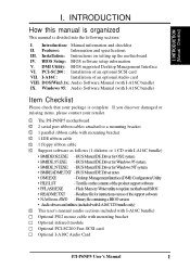
.... Text file on setting up the motherboard IV. Installation: Instructions on the contents of an optional Audio card VIII. DOS/Win3.1x: Audio Software Manual (with I -P6NP5 User's Manual 1 INTRODUCTION (Manual / Checklist) I . BIOS Setup: BIOS software setup information V. PCI-SC200: Installation of an optional SCSI card VII. Features: Information and specifications III. DMI Utility...
.... Text file on setting up the motherboard IV. Installation: Instructions on the contents of an optional Audio card VIII. DOS/Win3.1x: Audio Software Manual (with I -P6NP5 User's Manual 1 INTRODUCTION (Manual / Checklist) I . BIOS Setup: BIOS software setup information V. PCI-SC200: Installation of an optional SCSI card VII. Features: Information and specifications III. DMI Utility...
User Manual
Page 8
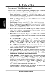
... with I/O subsystems. • Error Checking and Correcting (ECC): Using Intel's 440FX PCIset together with EPP and ECP capabilities. 16 bit I -P6NP5 User's Manual FEATURES (Features) II. FEATURES Features of 4MB, 8MB, 16MB, 32MB, 64MB to form a memory size between 8MB to page 18.) • Super... virtually automatic. • Multi-Speed Support: Supports one 150-200MHz Pentium Pro CPU on CPU) Level 2 cache so that supports the optional ASUS PCI-SC200 SCSI controller cards. 2 P/I /O fully decoded to the Infrared Module for the demanding PC user who wants a great many features in...
... with I/O subsystems. • Error Checking and Correcting (ECC): Using Intel's 440FX PCIset together with EPP and ECP capabilities. 16 bit I -P6NP5 User's Manual FEATURES (Features) II. FEATURES Features of 4MB, 8MB, 16MB, 32MB, 64MB to form a memory size between 8MB to page 18.) • Super... virtually automatic. • Multi-Speed Support: Supports one 150-200MHz Pentium Pro CPU on CPU) Level 2 cache so that supports the optional ASUS PCI-SC200 SCSI controller cards. 2 P/I /O fully decoded to the Infrared Module for the demanding PC user who wants a great many features in...
User Manual
Page 9
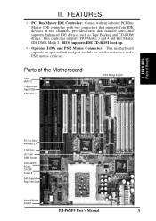
II. This controller supports PIO Modes 3 and 4 and Bus Master IDE DMA Mode 2. Parts of Board) PCI 5 or ASUS MediaBus 2.0 3 ISA Slots (4) 72-pin SIMM Sockets Intel's 440FX PCIset CPU ZIF Socket 8 Self-Powered Real Time Clock Infrared Module Support P/I /O ...motherboard supports an optional infrared port module for wireless interface and a PS/2 mouse cable set. FEATURES (Parts of the Motherboard Super Multi-I -P6NP5 User's Manual 3 FEATURES • PCI Bus Master IDE Controller: Comes with an onboard PCI Bus Master IDE controller with two connectors that supports four IDE ...
II. This controller supports PIO Modes 3 and 4 and Bus Master IDE DMA Mode 2. Parts of Board) PCI 5 or ASUS MediaBus 2.0 3 ISA Slots (4) 72-pin SIMM Sockets Intel's 440FX PCIset CPU ZIF Socket 8 Self-Powered Real Time Clock Infrared Module Support P/I /O ...motherboard supports an optional infrared port module for wireless interface and a PS/2 mouse cable set. FEATURES (Parts of the Motherboard Super Multi-I -P6NP5 User's Manual 3 FEATURES • PCI Bus Master IDE Controller: Comes with an onboard PCI Bus Master IDE controller with two connectors that supports four IDE ...
User Manual
Page 10
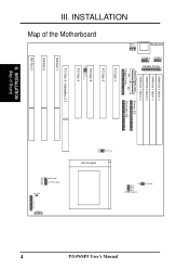
... 2 (Bank 0) SIMM Slot 1 (Bank 0) Board Power Input Primary IDE P9 P8 Floppy Drives Secondary IDE PCI Slot 1 PCI Slot 2 PCI Slot 3 JP10 JP13 Multi I -P6NP5 User's Manual III. ZIF Socket 8 JP12 JP5 JP7 JP6 JP4 CMOS RAM CPU:BUS Ratio JP1 JP15 JP16 JP17 JP18 Voltage Regulator Fan Power IDE LED Case...
... 2 (Bank 0) SIMM Slot 1 (Bank 0) Board Power Input Primary IDE P9 P8 Floppy Drives Secondary IDE PCI Slot 1 PCI Slot 2 PCI Slot 3 JP10 JP13 Multi I -P6NP5 User's Manual III. ZIF Socket 8 JP12 JP5 JP7 JP6 JP4 CMOS RAM CPU:BUS Ratio JP1 JP15 JP16 JP17 JP18 Voltage Regulator Fan Power IDE LED Case...
User Manual
Page 11
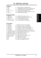
III. INSTALLATION (Map of Board) III. INSTALLATION Jumpers 1) JP10 2) JP13 3) JP12 4) JP15, 16, 17, 18 5) JP2, 3 6) JP4, 5, 6, 7 p. 7 Multi-I -P6NP5 User's Manual 5 IDE p. 22 Primary/Secondary IDE connectors (40-pin Blocks) 8) Turbo/Power (CON1) p. 22 Turbo LED/Power LED (2-pins) 9) SMI Switch (CON1) p. 22 SMI Switch lead (2-...
III. INSTALLATION (Map of Board) III. INSTALLATION Jumpers 1) JP10 2) JP13 3) JP12 4) JP15, 16, 17, 18 5) JP2, 3 6) JP4, 5, 6, 7 p. 7 Multi-I -P6NP5 User's Manual 5 IDE p. 22 Primary/Secondary IDE connectors (40-pin Blocks) 8) Turbo/Power (CON1) p. 22 Turbo LED/Power LED (2-pins) 9) SMI Switch (CON1) p. 22 SMI Switch lead (2-...
User Manual
Page 12
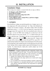
... shown graphically such as for short (On) and for open (Off). Jumpers with the keyboard connector away from the system. 6 P/I-P6NP5 User's Manual INSTALLATION (Jumpers) 1. The jumpers will be moved together. Settings with three pins. Install Expansion Cards 5. Connect Ribbon Cables, Cabinet Wires...such as diagramed. Hold components by the edges and try not to con- Unplug your computer. 1. Use the diagrams in this manual instead of jumper caps to touch the IC chips, leads, or circuitry. 3. WARNING: Computer motheboards and components contain very delicate ...
... shown graphically such as for short (On) and for open (Off). Jumpers with the keyboard connector away from the system. 6 P/I-P6NP5 User's Manual INSTALLATION (Jumpers) 1. The jumpers will be moved together. Settings with three pins. Install Expansion Cards 5. Connect Ribbon Cables, Cabinet Wires...such as diagramed. Hold components by the edges and try not to con- Unplug your computer. 1. Use the diagrams in this manual instead of jumper caps to touch the IC chips, leads, or circuitry. 3. WARNING: Computer motheboards and components contain very delicate ...
User Manual
Page 13
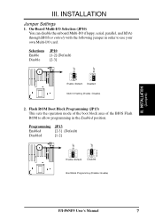
On-Board Multi-I/O Selection (JP10) You can disable the onboard Multi-I /O card. Selections Enable Disable JP10 [1-2] (Default) [2-3] JP10 JP10 1 2 3 Enable (Default) Disabled Multi I -P6NP5 User's Manual 7 Programming JP13 Enabled [2-3] (Default) Disabled [1-2] JP13 JP13 Enable (Default) 1 2 3 Disabled Boot Block Programming (Disable / Enable) P/I /O Setting (Enable / Disable) 2. INSTALLATION (Jumpers) III. INSTALLATION Jumper Settings 1. Flash ...
On-Board Multi-I/O Selection (JP10) You can disable the onboard Multi-I /O card. Selections Enable Disable JP10 [1-2] (Default) [2-3] JP10 JP10 1 2 3 Enable (Default) Disabled Multi I -P6NP5 User's Manual 7 Programming JP13 Enabled [2-3] (Default) Disabled [1-2] JP13 JP13 Enable (Default) 1 2 3 Disabled Boot Block Programming (Disable / Enable) P/I /O Setting (Enable / Disable) 2. INSTALLATION (Jumpers) III. INSTALLATION Jumper Settings 1. Flash ...
User Manual
Page 14
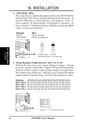
... [O] [S] [O] [S] [O] [S] [O] [S] JP16 (VID 1) [S] [S] [O] [O] [S] [S] [O] [O] [S] [S] [O] [O] [S] [S] [O] JP17 (VID 2) [S] [S] [S] [S] [O] [O] [O] [O] [S] [S] [S] [S] [O] [O] [O] JP18 (VID 3) [S] [S] [S] [S] [S] [S] [S] [S] [O] [O] [O] [O] [O] [O] [O] JP15 (VID 0) JP16 (VID 1) JP17 (VID 2) JP18 (VID 3) VID Support (Default) Voltage ID 0, 1, 2, 3 (VID Support or Manual) 8 P/I-P6NP5 User's Manual CMOS RAM (JP12) This clears the user-entered information stored in this case). INSTALLATION (Jumpers) Operation (Default) Clear Data CMOS RAM (Operation / Clear CMOS Data) 4. ...
... [O] [S] [O] [S] [O] [S] [O] [S] JP16 (VID 1) [S] [S] [O] [O] [S] [S] [O] [O] [S] [S] [O] [O] [S] [S] [O] JP17 (VID 2) [S] [S] [S] [S] [O] [O] [O] [O] [S] [S] [S] [S] [O] [O] [O] JP18 (VID 3) [S] [S] [S] [S] [S] [S] [S] [S] [O] [O] [O] [O] [O] [O] [O] JP15 (VID 0) JP16 (VID 1) JP17 (VID 2) JP18 (VID 3) VID Support (Default) Voltage ID 0, 1, 2, 3 (VID Support or Manual) 8 P/I-P6NP5 User's Manual CMOS RAM (JP12) This clears the user-entered information stored in this case). INSTALLATION (Jumpers) Operation (Default) Clear Data CMOS RAM (Operation / Clear CMOS Data) 4. ...

User Manual
Page 15
INSTALLATION (This page was intentionally left blank) III. INSTALLATION (Jumpers) P/I-P6NP5 User's Manual 9 III.
INSTALLATION (This page was intentionally left blank) III. INSTALLATION (Jumpers) P/I-P6NP5 User's Manual 9 III.
User Manual
Page 16
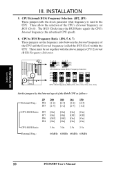
...] [Off] [On] [On] [Off] [On] [On] [On] [Off] [On] [On] CPU:BUS Ratio: 3.0x 3.0x 2.5x 2.5x External Freq.: 66MHz 60MHz 66MHz 60MHz 10 P/I-P6NP5 User's Manual CPU to the CPU. INSTALLATION (Jumpers) III. CPU External (BUS) Frequency Selection (JP2, JP3) These jumpers tells the clock generator what frequency to send to...
...] [Off] [On] [On] [Off] [On] [On] [On] [Off] [On] [On] CPU:BUS Ratio: 3.0x 3.0x 2.5x 2.5x External Freq.: 66MHz 60MHz 66MHz 60MHz 10 P/I-P6NP5 User's Manual CPU to the CPU. INSTALLATION (Jumpers) III. CPU External (BUS) Frequency Selection (JP2, JP3) These jumpers tells the clock generator what frequency to send to...
User Manual
Page 17
INSTALLATION (This page was intentionally left blank) III. INSTALLATION (Jumpers) P/I-P6NP5 User's Manual 11 III.
INSTALLATION (This page was intentionally left blank) III. INSTALLATION (Jumpers) P/I-P6NP5 User's Manual 11 III.

User Manual
Page 18
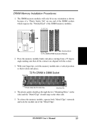
... Total System Memory = IMPORTANT: Each bank must have the same size and type (FPM, EDO, BEDO) of the same size memory modules. INSTALLATION (Memory) 12 P/I-P6NP5 User's Manual The DRAM can be installed in any or all modules.
... Total System Memory = IMPORTANT: Each bank must have the same size and type (FPM, EDO, BEDO) of the same size memory modules. INSTALLATION (Memory) 12 P/I-P6NP5 User's Manual The DRAM can be installed in any or all modules.
User Manual
Page 19
... the sides and the "Metal Clips" should snap on one end of the SIMM sockets which requires the "Notched End" of the "Metal Clips". P/I-P6NP5 User's Manual 13 The SIMM memory modules will only fit in SIMM Socket Metal Clip Plastic Safety Tab (This Side Only) Mounting Hole 4. With your finger tips...
... the sides and the "Metal Clips" should snap on one end of the SIMM sockets which requires the "Notched End" of the "Metal Clips". P/I-P6NP5 User's Manual 13 The SIMM memory modules will only fit in SIMM Socket Metal Clip Plastic Safety Tab (This Side Only) Mounting Hole 4. With your finger tips...

User Manual
Page 20
INSTALLATION (This page was intentionally left blank) 14 P/I-P6NP5 User's Manual III.
INSTALLATION (This page was intentionally left blank) 14 P/I-P6NP5 User's Manual III.
User Manual
Page 21
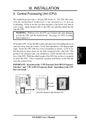
... on your system. The picture is for reference only, you install. If this is required to the other half. Insert the CPU with Pentium Pro P/I-P6NP5 User's Manual 15 WARNING: Without a fan, the CPU can overheat and cause damage to prevent overheating. With the added weight of the CPU. Lock Lever CPU...
... on your system. The picture is for reference only, you install. If this is required to the other half. Insert the CPU with Pentium Pro P/I-P6NP5 User's Manual 15 WARNING: Without a fan, the CPU can overheat and cause damage to prevent overheating. With the added weight of the CPU. Lock Lever CPU...


