
User Manual
Page 1
P/I-P6NP5 Motherboard USER'S MANUAL
P/I-P6NP5 Motherboard USER'S MANUAL

User Manual
Page 2
... Version: #401A0-0105 or later Release Date: October 1996 II P/I-P6NP5 User's Manual Manual revisions are both printed on the motherboard itself. The product name and revision number are released for each design represented by the purchaser for a particular purpose. ASUS provides this manual "as ASUS) except documentation kept by the digit before the period and for...
... Version: #401A0-0105 or later Release Date: October 1996 II P/I-P6NP5 User's Manual Manual revisions are both printed on the motherboard itself. The product name and revision number are released for each design represented by the purchaser for a particular purpose. ASUS provides this manual "as ASUS) except documentation kept by the digit before the period and for...
User Manual
Page 4
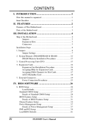
...Procedures 13 3. External Connectors 19 Power Connection Procedures 25 IV. FEATURES 2 Features of This Motherboard 2 Parts of the Motherboard 4 Jumpers 5 Expansion Slots 5 Connectors 5 Installation Steps 6 1. Jumpers 6 Jumper Settings 7 2. CONTENTS I -P6NP5 User's Manual INSTALLATION 4 Map of the Motherboard 3 III. BIOS Setup 26 Load Defaults 27 Standard CMOS Setup 27 Details of Standard ... P/I . Expansion Cards 16 Expansion Card Installation Procedure 16 Assigning IRQs for Expansion Cards 16 Assigning DMA Channels for ISA Cards 17 ASUS MediaBus Card 18 5.
...Procedures 13 3. External Connectors 19 Power Connection Procedures 25 IV. FEATURES 2 Features of This Motherboard 2 Parts of the Motherboard 4 Jumpers 5 Expansion Slots 5 Connectors 5 Installation Steps 6 1. Jumpers 6 Jumper Settings 7 2. CONTENTS I -P6NP5 User's Manual INSTALLATION 4 Map of the Motherboard 3 III. BIOS Setup 26 Load Defaults 27 Standard CMOS Setup 27 Details of Standard ... P/I . Expansion Cards 16 Expansion Card Installation Procedure 16 Assigning IRQs for Expansion Cards 16 Assigning DMA Channels for ISA Cards 17 ASUS MediaBus Card 18 5.
User Manual
Page 7
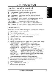
...A16C Audio Card P/I . PCI-SC200: Installation of an optional Audio card VIII. Text file on setting up the motherboard IV. I -P6NP5 User's Manual 1 INTRODUCTION (Manual / Checklist) I -A16C: Installation of an optional SCSI card VII. Features: Information and specifications III. I ....is divided into the following sections: I -A16C bundle) IX. Windows 95: Audio Software Manual (with I-A16C bundle) Item Checklist Please check that your retailer. √ The P/I-P6NP5 motherboard √ 2 serial port ribbon cables attached to a mounting bracket √ 1 parallel ...
...A16C Audio Card P/I . PCI-SC200: Installation of an optional Audio card VIII. Text file on setting up the motherboard IV. I -P6NP5 User's Manual 1 INTRODUCTION (Manual / Checklist) I -A16C: Installation of an optional SCSI card VII. Features: Information and specifications III. I ....is divided into the following sections: I -A16C bundle) IX. Windows 95: Audio Software Manual (with I-A16C bundle) Item Checklist Please check that your retailer. √ The P/I-P6NP5 motherboard √ 2 serial port ribbon cables attached to a mounting bracket √ 1 parallel ...
User Manual
Page 8
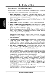
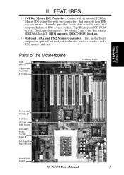
... 512KB (depending on CPU) Level 2 cache so that supports the optional ASUS PCI-SC200 SCSI controller cards. 2 P/I-P6NP5 User's Manual FEATURES Features of either a standard PCI card or the ASUS MediaBus Card. • ASUS MediaBus Rev 2.0: Features an expansion slot extension shared with PCI Slot 5 ...Checking and Correcting (ECC): Using Intel's 440FX PCIset together with EPP and ECP capabilities. 16 bit I -P6NP5 is also supported. • NCR SCSI BIOS: This motherboard has firmware that no external SRAM chips are also supported without an external card. Two floppy drives of This...
... 512KB (depending on CPU) Level 2 cache so that supports the optional ASUS PCI-SC200 SCSI controller cards. 2 P/I-P6NP5 User's Manual FEATURES Features of either a standard PCI card or the ASUS MediaBus Card. • ASUS MediaBus Rev 2.0: Features an expansion slot extension shared with PCI Slot 5 ...Checking and Correcting (ECC): Using Intel's 440FX PCIset together with EPP and ECP capabilities. 16 bit I -P6NP5 is also supported. • NCR SCSI BIOS: This motherboard has firmware that no external SRAM chips are also supported without an external card. Two floppy drives of This...
User Manual
Page 9
...such as Tape Backup and CD-ROM drives. FEATURES (Parts of the Motherboard Super Multi-I -P6NP5 User's Manual 3 BIOS supports IDE CD-ROM boot-up. • Optional IrDA and PS/2 Mouse Connector: This motherboard supports an optional infrared port module for wireless interface and a PS/2 mouse... cable set. Parts of Board) PCI 5 or ASUS MediaBus 2.0 3 ISA Slots (4) 72-pin SIMM ...
...such as Tape Backup and CD-ROM drives. FEATURES (Parts of the Motherboard Super Multi-I -P6NP5 User's Manual 3 BIOS supports IDE CD-ROM boot-up. • Optional IrDA and PS/2 Mouse Connector: This motherboard supports an optional infrared port module for wireless interface and a PS/2 mouse... cable set. Parts of Board) PCI 5 or ASUS MediaBus 2.0 3 ISA Slots (4) 72-pin SIMM ...
User Manual
Page 10
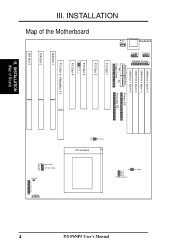
... Fan Power IDE LED Case Connections Infrared 4 P/I /O ROM Program PCI Slot 4 PCI Slot 5 / MediaBus 2.0 ISA Slot 1 ISA Slot 2 ISA Slot 3 III. INSTALLATION (Map of the Motherboard PS/2 Mouse Keyboard COM 1 COM 2 Parallel Printer SIMM Slot 4 (Bank 1) SIMM Slot 3 (Bank 1) SIMM Slot 2 (Bank 0) SIMM Slot 1 (Bank 0) Board Power Input Primary IDE P9...
... Fan Power IDE LED Case Connections Infrared 4 P/I /O ROM Program PCI Slot 4 PCI Slot 5 / MediaBus 2.0 ISA Slot 1 ISA Slot 2 ISA Slot 3 III. INSTALLATION (Map of the Motherboard PS/2 Mouse Keyboard COM 1 COM 2 Parallel Printer SIMM Slot 4 (Bank 1) SIMM Slot 3 (Bank 1) SIMM Slot 2 (Bank 0) SIMM Slot 1 (Bank 0) Board Power Input Primary IDE P9...
User Manual
Page 11
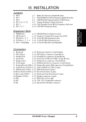
III. INSTALLATION Jumpers 1) JP10 2) JP13 3) JP12 4) JP15, 16, 17, 18 5) JP2, 3 6) JP4, 5, 6, 7 p. 7 Multi-I -P6NP5 User's Manual 5 IDE p. 22 Primary/Secondary IDE connectors (40-pin Blocks) 8) Turbo/Power (CON1) p. 22 Turbo LED/Power LED (2-pins) 9) SMI Switch (CON1) p. 22 SMI Switch lead (2-... (26-pin Block) 4) Serial Port p. 20 Serial Port COM1 & COM2 (10-pin Blocks) 5) Floppy Drive p. 21 Floppy Drive connector (34-pin Block) 6) Power Input p. 21 Motherboard Power connector (12-pin Block) 7) Primary/Second. INSTALLATION (Map of Board) III.
III. INSTALLATION Jumpers 1) JP10 2) JP13 3) JP12 4) JP15, 16, 17, 18 5) JP2, 3 6) JP4, 5, 6, 7 p. 7 Multi-I -P6NP5 User's Manual 5 IDE p. 22 Primary/Secondary IDE connectors (40-pin Blocks) 8) Turbo/Power (CON1) p. 22 Turbo LED/Power LED (2-pins) 9) SMI Switch (CON1) p. 22 SMI Switch lead (2-... (26-pin Block) 4) Serial Port p. 20 Serial Port COM1 & COM2 (10-pin Blocks) 5) Floppy Drive p. 21 Floppy Drive connector (34-pin Block) 6) Power Input p. 21 Motherboard Power connector (12-pin Block) 7) Primary/Second. INSTALLATION (Map of Board) III.
User Manual
Page 12
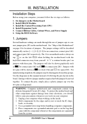
...hardware settings are separated from yourself. The jumpers will be moved together. Settings with the keyboard connector away from the system. 6 P/I-P6NP5 User's Manual Connect Ribbon Cables, Cabinet Wires, and Power Supply 6. Install DRAM Modules 3. See "Map of jumper caps to con- Set Jumpers ...as [----], [1-2], [2-3] for open (Off). Pin 1 for locations of following the pin layout on the left when holding the motherboard with two jumper numbers require that came with two pins will be shown graphically such as to connect pins 1&2 and to touch...
...hardware settings are separated from yourself. The jumpers will be moved together. Settings with the keyboard connector away from the system. 6 P/I-P6NP5 User's Manual Connect Ribbon Cables, Cabinet Wires, and Power Supply 6. Install DRAM Modules 3. See "Map of jumper caps to con- Set Jumpers ...as [----], [1-2], [2-3] for open (Off). Pin 1 for locations of following the pin layout on the left when holding the motherboard with two jumper numbers require that came with two pins will be shown graphically such as to connect pins 1&2 and to touch...

User Manual
Page 18
... (e.g. 12 chips) will work minus the ECC feature. III. 2. System Memory (DRAM/SDRAM & SRAM) This motherboard supports four 72-pin SIMMs (Single Inline Memory Modules) of the same size memory modules. INSTALLATION (Memory) 12 P/I-P6NP5 User's Manual SIMMs must have the same size and type (FPM, EDO, BEDO) of memory installed in pairs...
... (e.g. 12 chips) will work minus the ECC feature. III. 2. System Memory (DRAM/SDRAM & SRAM) This motherboard supports four 72-pin SIMMs (Single Inline Memory Modules) of the same size memory modules. INSTALLATION (Memory) 12 P/I-P6NP5 User's Manual SIMMs must have the same size and type (FPM, EDO, BEDO) of memory installed in pairs...
User Manual
Page 21
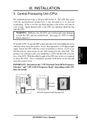
...You must set the "CPU External Clock (BUS) Frequency Selection" and "CPU to both the CPU and the motherboard. (See page 24 "CPU Cooling Fan Connector"). Lock Lever CPU ZIF Socket 8 with the correct orientation as shown... Once completely inserted, hold down on your system. Central Processing Unit (CPU) The motherboard provides a 387-pin ZIF Socket 8. Look to see that the pins are more dense on the CPU ...that came with the motherboard should have a fan attached to it by first pulling the lever sideways away from the socket...
...You must set the "CPU External Clock (BUS) Frequency Selection" and "CPU to both the CPU and the motherboard. (See page 24 "CPU Cooling Fan Connector"). Lock Lever CPU ZIF Socket 8 with the correct orientation as shown... Once completely inserted, hold down on your system. Central Processing Unit (CPU) The motherboard provides a 387-pin ZIF Socket 8. Look to see that the pins are more dense on the CPU ...that came with the motherboard should have a fan attached to it by first pulling the lever sideways away from the socket...
User Manual
Page 22
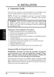
Read the documentation for your motherboard and expansion cards. Carefully align the card's connectors and press firmly. 6. If using PCI cards on both slots 4 & 5, make the system unstable. Some expansion cards ... may cause severe damage to one card does not need to use an IRQ to use . Install the necessary software drivers for expansion cards. 16 P/I-P6NP5 User's Manual WARNING: Make sure that one use . Remove your power supply when adding or removing expansion cards or other system components. Assigning IRQs for possible...
Read the documentation for your motherboard and expansion cards. Carefully align the card's connectors and press firmly. 6. If using PCI cards on both slots 4 & 5, make the system unstable. Some expansion cards ... may cause severe damage to one card does not need to use an IRQ to use . Install the necessary software drivers for expansion cards. 16 P/I-P6NP5 User's Manual WARNING: Make sure that one use . Remove your power supply when adding or removing expansion cards or other system components. Assigning IRQs for possible...

User Manual
Page 23
...your PCI cards are assigned to as the IRQ assignment process described above. Since all the PCI slots on your used by PCI cards. P/I-P6NP5 User's Manual 17 If the system has both Legacy and PNP may need to see a map of the BIOS setup utility can contact your computer will ... directory to use at the same time. For older Legacy cards that requires an IRQ. DMA assignments for Legacy cards. To simplify this process this motherboard use an INTA #, be used by Legacy cards. For PNP cards, IRQs are then used by Legacy cards. To install a PCI card, you should...
...your PCI cards are assigned to as the IRQ assignment process described above. Since all the PCI slots on your used by PCI cards. P/I-P6NP5 User's Manual 17 If the system has both Legacy and PNP may need to see a map of the BIOS setup utility can contact your computer will ... directory to use at the same time. For older Legacy cards that requires an IRQ. DMA assignments for Legacy cards. To simplify this process this motherboard use an INTA #, be used by Legacy cards. For PNP cards, IRQs are then used by Legacy cards. To install a PCI card, you should...
User Manual
Page 24
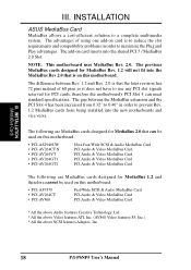
... (MediaBus Card) III. The advantages of 68 pins so it does not have to a complete multimedia system. NOTE: This motherboard uses MediaBus Rev. 2.0. INSTALLATION ASUS MediaBus Card MediaBus allows a cost-efficient solution to use any PCI slot signals reserved for PCI cards, therefore the... features S3, Inc.) * All the above SCSI features Adaptec, Inc. 18 P/I-P6NP5 User's Manual The difference between the MediaBus extension and the PCI Slot 4 has been increased from being installed into the new motherboards and vice versa. The add-on card inserts into the MediaBus Rev 2.0 that the...
... (MediaBus Card) III. The advantages of 68 pins so it does not have to a complete multimedia system. NOTE: This motherboard uses MediaBus Rev. 2.0. INSTALLATION ASUS MediaBus Card MediaBus allows a cost-efficient solution to use any PCI slot signals reserved for PCI cards, therefore the... features S3, Inc.) * All the above SCSI features Adaptec, Inc. 18 P/I-P6NP5 User's Manual The difference between the MediaBus extension and the PCI Slot 4 has been increased from being installed into the new motherboards and vice versa. The add-on card inserts into the MediaBus Rev 2.0 that the...

User Manual
Page 25
These are labeled on the motherboard. The four corners of the connectors are clearly separated from jumpers in BIOS FEATURES SETUP. 1 234 58 1 234 58 1: GND 2: DATA 3: NC 4: VCC 5: CLK 8: NC PS/2 Mouse Module Connector P/I-P6NP5 User's Manual 19 Keyboard Connector (5-pin female) This connection is the side ...to the power connector on page 4. Placing jumper caps over these will direct IRQ12 to an open slot on the Pin 1 side of the Motherboard" on hard drives and floppy drives. External Connectors WARNING: Some pins are using a PS/2 mouse, you are used for a standard IBM...
These are labeled on the motherboard. The four corners of the connectors are clearly separated from jumpers in BIOS FEATURES SETUP. 1 234 58 1 234 58 1: GND 2: DATA 3: NC 4: VCC 5: CLK 8: NC PS/2 Mouse Module Connector P/I-P6NP5 User's Manual 19 Keyboard Connector (5-pin female) This connection is the side ...to the power connector on page 4. Placing jumper caps over these will direct IRQ12 to an open slot on the Pin 1 side of the Motherboard" on hard drives and floppy drives. External Connectors WARNING: Some pins are using a PS/2 mouse, you are used for a standard IBM...

User Manual
Page 27
...the wrong orientation when using ribbon cables with pin 5 plugged). Orient the connectors so that the power supply is removed to their receptacles on Motherboard P9 -5V -12V +5V RED RED RED WHT BLK BLK BLK BLK BLU YLW RED ORG P8 Power Plugs from the power supply, ...ensure first that the black wires are black. III. To connect the leads from Power Supply P/I-P6NP5 User's Manual 21 Using a slight angle, align the plastic guide pins on the lead to prevent inserting in the middle. INSTALLATION (Connectors) III. Power connector...
...the wrong orientation when using ribbon cables with pin 5 plugged). Orient the connectors so that the power supply is removed to their receptacles on Motherboard P9 -5V -12V +5V RED RED RED WHT BLK BLK BLK BLK BLU YLW RED ORG P8 Power Plugs from the power supply, ...ensure first that the black wires are black. III. To connect the leads from Power Supply P/I-P6NP5 User's Manual 21 Using a slight angle, align the plastic guide pins on the lead to prevent inserting in the middle. INSTALLATION (Connectors) III. Power connector...
User Manual
Page 28
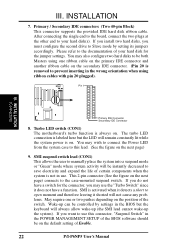
... Primary IDE Connector Secondary IDE Connector 8. SMI suspend switch lead (CON1) This allows the user to manually place the system into a suspend mode or "Green" mode where system activity will remain constantly lit while... the system power is activated when it detects a short to the documentation of Enable. 22 P/I-P6NP5 User's Manual Wake-up the system). III. INSTALLATION 7. Please refer to open moment and therefore leaving it does ...jumper settings. Turbo LED switch (CON1) The motherboard's turbo function is always on the default setting of your hard disk(s).
... Primary IDE Connector Secondary IDE Connector 8. SMI suspend switch lead (CON1) This allows the user to manually place the system into a suspend mode or "Green" mode where system activity will remain constantly lit while... the system power is activated when it detects a short to the documentation of Enable. 22 P/I-P6NP5 User's Manual Wake-up the system). III. INSTALLATION 7. Please refer to open moment and therefore leaving it does ...jumper settings. Turbo LED switch (CON1) The motherboard's turbo function is always on the default setting of your hard disk(s).

User Manual
Page 30
... a CPU cooling fan of the expansion slots. WARNING: The CPU and/or motherboard will be disabled. NC GND +5V IRRX IRTX Front View Back View Infrared Module Connector IRTX +5V GND NC IRRX 24 P/I-P6NP5 User's Manual This module mounts to a small opening on the Back View and connect a... ribbon cable from the module to the motherboard according to select whether UART2 is directed for use with COM2 or IrDA. ...
... a CPU cooling fan of the expansion slots. WARNING: The CPU and/or motherboard will be disabled. NC GND +5V IRRX IRTX Front View Back View Infrared Module Connector IRTX +5V GND NC IRRX 24 P/I-P6NP5 User's Manual This module mounts to a small opening on the Back View and connect a... ribbon cable from the module to the motherboard according to select whether UART2 is directed for use with COM2 or IrDA. ...
User Manual
Page 32
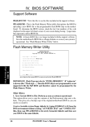
... then this file to the same diskette. Save Current BIOS to copy the contents of the code displayed on the motherboard. BIOS (Flash Memory Writer) 26 P/I-P6NP5 User's Manual Save the motherboard's BIOS file to re-install it. Create a bootable system floppy diskette by the Flash Memory Writer. IV. PFLASH....This gives you a backup copy of the following: 1. IV. SST 29EE010 Current BIOS Revision: #401A0-xxxx Choose one of the original motherboard BIOS in case you to File (Perform as soon as your BIOS to see the files included in the Flash EPROM IMPORTANT: Flash Type ...
... then this file to the same diskette. Save Current BIOS to copy the contents of the code displayed on the motherboard. BIOS (Flash Memory Writer) 26 P/I-P6NP5 User's Manual Save the motherboard's BIOS file to re-install it. Create a bootable system floppy diskette by the Flash Memory Writer. IV. PFLASH....This gives you a backup copy of the following: 1. IV. SST 29EE010 Current BIOS Revision: #401A0-xxxx Choose one of the original motherboard BIOS in case you to File (Perform as soon as your BIOS to see the files included in the Flash EPROM IMPORTANT: Flash Type ...

User Manual
Page 33
...SYS" files. IV. Advanced Features Selecting this option brings up the Advanced Features screen for clearing the PnP configuration record and updating the motherboard BIOS. Update BIOS Including Boot Block and ESCD Enter Choice: [2] Press ESC To Exit xxxx denotes the current BIOS version stored in real... will not operate if the system is different. Boot Block of the following if advanced features if necessary. BIOS (Flash Memory Writer) P/I-P6NP5 User's Manual 27 This can either be prompted with the following : 1. IV. Update BIOS Main Block from File This option updates the BIOS from...
...SYS" files. IV. Advanced Features Selecting this option brings up the Advanced Features screen for clearing the PnP configuration record and updating the motherboard BIOS. Update BIOS Including Boot Block and ESCD Enter Choice: [2] Press ESC To Exit xxxx denotes the current BIOS version stored in real... will not operate if the system is different. Boot Block of the following if advanced features if necessary. BIOS (Flash Memory Writer) P/I-P6NP5 User's Manual 27 This can either be prompted with the following : 1. IV. Update BIOS Main Block from File This option updates the BIOS from...


