
User Guide
Page 4
... off the computer 3-2 3.2.1 Using the OS shut down function 3-2 3.2.2 Using the dual function power switch 3-2 Chapter 4: BIOS setup 4.1 Managing and updating your BIOS 4-1 4.1.1 Creating a bootable floppy disk 4-1 4.1.2 AFUDOS utility 4-2 4.1.3 ASUS CrashFree BIOS 2 utility 4-5 4.1.4 ASUS Update utility 4-7 4.2 BIOS setup program 4-10 4.2.1 BIOS menu screen 4-11 4.2.2 Menu bar 4-11 4.2.3 Navigation keys 4-11 4.2.4 Menu items 4-12 4.2.5 Sub-menu items 4-12...
... off the computer 3-2 3.2.1 Using the OS shut down function 3-2 3.2.2 Using the dual function power switch 3-2 Chapter 4: BIOS setup 4.1 Managing and updating your BIOS 4-1 4.1.1 Creating a bootable floppy disk 4-1 4.1.2 AFUDOS utility 4-2 4.1.3 ASUS CrashFree BIOS 2 utility 4-5 4.1.4 ASUS Update utility 4-7 4.2 BIOS setup program 4-10 4.2.1 BIOS menu screen 4-11 4.2.2 Menu bar 4-11 4.2.3 Navigation keys 4-11 4.2.4 Menu items 4-12 4.2.5 Sub-menu items 4-12...
User Guide
Page 5
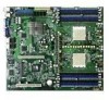
...Chapter 5: RAID configuration 5.1 Setting up RAID 5-1 5.1.1 RAID definitions 5-1 5.1.2 Installing hard disk drives 5-2 5.1.3 RAID configuration utility 5-2 5.2 NVIDIA® RAID configurations 5-3 5.2.1 Setting the BIOS RAID items 5-3 5.2.2 Entering the NVIDIA® RAID Utility 5-4 5.2.3 Creating a RAID 0 set (Stripe 5-5 5.2.4 Creating a RAID 1 set (Mirror 5-7 5.2.5 Rebuilding a RAID ...Support CD information 6-4 6.4.1 Running the support CD 6-4 6.4.2 Drivers menu 6-5 6.4.3 Management Software 6-6 6.4.4 Utilities 6-7 Appendix: Reference information A.1 K8N-DRE block diagram A-1 v
...Chapter 5: RAID configuration 5.1 Setting up RAID 5-1 5.1.1 RAID definitions 5-1 5.1.2 Installing hard disk drives 5-2 5.1.3 RAID configuration utility 5-2 5.2 NVIDIA® RAID configurations 5-3 5.2.1 Setting the BIOS RAID items 5-3 5.2.2 Entering the NVIDIA® RAID Utility 5-4 5.2.3 Creating a RAID 0 set (Stripe 5-5 5.2.4 Creating a RAID 1 set (Mirror 5-7 5.2.5 Rebuilding a RAID ...Support CD information 6-4 6.4.1 Running the support CD 6-4 6.4.2 Drivers menu 6-5 6.4.3 Management Software 6-6 6.4.4 Utilities 6-7 Appendix: Reference information A.1 K8N-DRE block diagram A-1 v
User Guide
Page 8
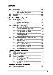
... have been added by your dealer. It includes description of shutting down the system. • Chapter 4: BIOS setup Tells how to change system settings through the BIOS Setup menus. ASUS websites The ASUS website provides updated information on the motherboard. • Chapter 3: Powering up This chapter describes the power up sequence, the vocal POST messages...
... have been added by your dealer. It includes description of shutting down the system. • Chapter 4: BIOS setup Tells how to change system settings through the BIOS Setup menus. ASUS websites The ASUS website provides updated information on the motherboard. • Chapter 3: Powering up This chapter describes the power up sequence, the vocal POST messages...

User Guide
Page 10
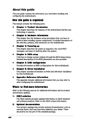
...ASUS Q-Fan 2 ASUS CrashFree BIOS 2 ASUS MyLogo2 Rear panel 1 x Serial port (COM1) 2 x LAN (RJ-45) port 1 x VGA port 2 x USB 2.0 ports 1 x PS/2 keyboard port 1 x PS/2 mouse port BIOS features 8 Mb Flash ROM, AMI BIOS, PnP, DMI2.0, WfM2.0, SM BIOS 2.3 Power Requirement ATX power supply (with 24-pin and 8-pin 12 V plugs) ATX 12 V 2.0 compliant (continued on board; K8N-DRE... MHz DDR memory modules Supports up to 32 GB system memory (Note: Tested only up to 16 GB on this motherboard due to 2 GB DDR availability) 1 x PCI Express x16 slot 1 x PCI slot NVIDIA® nForce Professional 2200...
...ASUS Q-Fan 2 ASUS CrashFree BIOS 2 ASUS MyLogo2 Rear panel 1 x Serial port (COM1) 2 x LAN (RJ-45) port 1 x VGA port 2 x USB 2.0 ports 1 x PS/2 keyboard port 1 x PS/2 mouse port BIOS features 8 Mb Flash ROM, AMI BIOS, PnP, DMI2.0, WfM2.0, SM BIOS 2.3 Power Requirement ATX power supply (with 24-pin and 8-pin 12 V plugs) ATX 12 V 2.0 compliant (continued on board; K8N-DRE... MHz DDR memory modules Supports up to 32 GB system memory (Note: Tested only up to 16 GB on this motherboard due to 2 GB DDR availability) 1 x PCI Express x16 slot 1 x PCI slot NVIDIA® nForce Professional 2200...
User Guide
Page 18
... the fan speeds according to the system loading to buy a replacement ROM chip. ASUS MyLogo2™ This new feature present in the motherboard allows you to restore the original BIOS data from the support CD in case when the BIOS codes and data are corrupted. This protection eliminates the need to ensure quiet, cool...
... the fan speeds according to the system loading to buy a replacement ROM chip. ASUS MyLogo2™ This new feature present in the motherboard allows you to restore the original BIOS data from the support CD in case when the BIOS codes and data are corrupted. This protection eliminates the need to ensure quiet, cool...

User Guide
Page 27
.../2 keyboard port (purple) 3. VGA port 6. PCI Express x16 slot Jumpers 1. BIOS recovery setting (3-pin RECOVERY1) 7. Serial (COM 1) port 5. LAN 2 (RJ-45) port Page 2-9 2-12 2-17 Page 2-18 2-19 2-19 2-20 2-20 2-21 2-21 Page 2-22 2-22 2-22 2-22 2-22 2-22 2-22 ASUS K8N-DRE 2-7 DDR DIMM sockets 3. Clear RTC RAM (CLRTC1) 2. CPU sockets 2. Keyboard...
.../2 keyboard port (purple) 3. VGA port 6. PCI Express x16 slot Jumpers 1. BIOS recovery setting (3-pin RECOVERY1) 7. Serial (COM 1) port 5. LAN 2 (RJ-45) port Page 2-9 2-12 2-17 Page 2-18 2-19 2-19 2-20 2-20 2-21 2-21 Page 2-22 2-22 2-22 2-22 2-22 2-22 2-22 ASUS K8N-DRE 2-7 DDR DIMM sockets 3. Clear RTC RAM (CLRTC1) 2. CPU sockets 2. Keyboard...

User Guide
Page 36
...the expansion card. 2-16 Chapter 2: Hardware information Turn on the slot. 5. Refer to the card. Keep the screw for information on BIOS setup. 2. The following sub-sections describe the slots and the expansion cards that you intend to unplug the power cord before adding or...). 3. Failure to install expansion cards. 2.5 Expansion slots In the future, you may need to do so may cause you physical injury and damage motherboard components. 2.5.1 Installing an expansion card To install an expansion card: 1. Make sure to use . 4. Align the riser card connector with the slot...
...the expansion card. 2-16 Chapter 2: Hardware information Turn on the slot. 5. Refer to the card. Keep the screw for information on BIOS setup. 2. The following sub-sections describe the slots and the expansion cards that you intend to unplug the power cord before adding or...). 3. Failure to install expansion cards. 2.5 Expansion slots In the future, you may need to do so may cause you physical injury and damage motherboard components. 2.5.1 Installing an expansion card To install an expansion card: 1. Make sure to use . 4. Align the riser card connector with the slot...
User Guide
Page 38
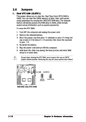
... from pins 1-2 (default) to re-enter data. To erase the RTC RAM: 1. Hold down the key during the boot process and enter BIOS setup to pins 2-3. Except when clearing the RTC RAM, never remove the cap on pins 2-3 for about 5~10 seconds, then move the cap...date, time, and system setup parameters by erasing the CMOS RTC RAM data. Keep the cap on CLRTC jumper default position. K8N-DRE ® CLRTC1 1 2 Normal (Default) 2 3 Clear CMOS K8N-DRE Clear RTC RAM 2-18 Chapter 2: Hardware information Remove the onboard battery. 3. Removing the cap will cause system boot failure!...
... from pins 1-2 (default) to re-enter data. To erase the RTC RAM: 1. Hold down the key during the boot process and enter BIOS setup to pins 2-3. Except when clearing the RTC RAM, never remove the cap on pins 2-3 for about 5~10 seconds, then move the cap...date, time, and system setup parameters by erasing the CMOS RTC RAM data. Keep the cap on CLRTC jumper default position. K8N-DRE ® CLRTC1 1 2 Normal (Default) 2 3 Clear CMOS K8N-DRE Clear RTC RAM 2-18 Chapter 2: Hardware information Remove the onboard battery. 3. Removing the cap will cause system boot failure!...
User Guide
Page 39
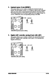
... wake-up the computer when you press a key on the +5VSB lead, and a corresponding setting in the BIOS. K8N-DRE ® LAN1_EN1 1 2 Enable (Default) 2 3 Disable K8N-DRE LAN1_EN1 setting ASUS K8N-DRE 2-19 This feature requires an ATX power supply that can supply at least 1A on the keyboard (the default is the Space Bar). Gigabit LAN1...; BCM5721 Gigabit LAN1 controller. Set this jumper to pins 1-2 (+5VSB) to activate the Gigabit LAN feature. Set to pins 1-2 to wake up feature. 2. K8N-DRE ® KBPWR1 1 2 +5VSB 2 3 +5V (Default) K8N-DRE Keyboard power setting 3 .
... wake-up the computer when you press a key on the +5VSB lead, and a corresponding setting in the BIOS. K8N-DRE ® LAN1_EN1 1 2 Enable (Default) 2 3 Disable K8N-DRE LAN1_EN1 setting ASUS K8N-DRE 2-19 This feature requires an ATX power supply that can supply at least 1A on the keyboard (the default is the Space Bar). Gigabit LAN1...; BCM5721 Gigabit LAN1 controller. Set this jumper to pins 1-2 (+5VSB) to activate the Gigabit LAN feature. Set to pins 1-2 to wake up feature. 2. K8N-DRE ® KBPWR1 1 2 +5VSB 2 3 +5V (Default) K8N-DRE Keyboard power setting 3 .

User Guide
Page 41
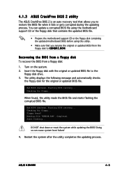
K8N-DRE ® K8N-DRE VGA setting ASUS K8N-DRE VGA_EN1 1 2 Enable (Default) 2 3 Disable 2-21 To recover the BIOS: 1.Turn OFF your computer. 7.Replace the jumper cap from a floppy disk in the floppy then reflashes the BIOS. 6.When finished, shut down the key during the boot process and enter BIOS setup to enable or disable the onboard ATI Rage XL video...
K8N-DRE ® K8N-DRE VGA setting ASUS K8N-DRE VGA_EN1 1 2 Enable (Default) 2 3 Disable 2-21 To recover the BIOS: 1.Turn OFF your computer. 7.Replace the jumper cap from a floppy disk in the floppy then reflashes the BIOS. 6.When finished, shut down the key during the boot process and enter BIOS setup to enable or disable the onboard ATI Rage XL video...

User Guide
Page 51
NMIBTN# MLED+ GND MLED- The speaker allows you turn on the BIOS settings. Pressing the power switch for more than four seconds while the system is ON turns the system ...panel connector is for the chassis-mounted system warning speaker. The IDE LED lights up when you to the HDD. ASUS K8N-DRE 2-31 Connect the chassis power LED cable to this connector. Connect the HDD Activity LED cable to this connector. If... power LED (Green 3-pin POWERLED) This 3-pin connector is color-coded for the HDD Activity LED. K8N-DRE PANEL1 ® HDLED+ POWERLED+ HDLED-
NMIBTN# MLED+ GND MLED- The speaker allows you turn on the BIOS settings. Pressing the power switch for more than four seconds while the system is ON turns the system ...panel connector is for the chassis-mounted system warning speaker. The IDE LED lights up when you to the HDD. ASUS K8N-DRE 2-31 Connect the chassis power LED cable to this connector. Connect the HDD Activity LED cable to this connector. If... power LED (Green 3-pin POWERLED) This 3-pin connector is color-coded for the HDD Activity LED. K8N-DRE PANEL1 ® HDLED+ POWERLED+ HDLED-
User Guide
Page 55
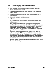
... or additional messages appear on , hold down the key to enter the BIOS Setup. Be sure that is equipped with ATX power supplies, the system LED lights up when you turned on the power, the system may light up or switch between orange and green after ... screen. The system then runs the power-on test. If you do not see anything within 30 seconds from the time you press the ATX power button. ASUS K8N-DRE 3-1 If your retailer for the first time 1. Check the jumper settings and connections or call your monitor complies with the last device on the...
... or additional messages appear on , hold down the key to enter the BIOS Setup. Be sure that is equipped with ATX power supplies, the system LED lights up when you turned on the power, the system may light up or switch between orange and green after ... screen. The system then runs the power-on test. If you do not see anything within 30 seconds from the time you press the ATX power button. ASUS K8N-DRE 3-1 If your retailer for the first time 1. Check the jumper settings and connections or call your monitor complies with the last device on the...
User Guide
Page 56
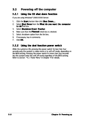
... the power switch for less than four seconds lets the system enter the soft-off mode regardless of the BIOS setting. Select S h u t D o w n from the list box. 6. 3.2 Powering off mode, depending on the BIOS setting. Make sure that the P l a n n e d check box is ON, pressing the power switch for more than four seconds puts...
... the power switch for less than four seconds lets the system enter the soft-off mode regardless of the BIOS setting. Select S h u t D o w n from the list box. 6. 3.2 Powering off mode, depending on the BIOS setting. Make sure that the P l a n n e d check box is ON, pressing the power switch for more than four seconds puts...
User Guide
Page 57
This chapter tells how to change the system settings through the BIOS Setup menus. Detailed descriptions of the BIOS parameters are also provided. 4 BIOS setup
This chapter tells how to change the system settings through the BIOS Setup menus. Detailed descriptions of the BIOS parameters are also provided. 4 BIOS setup
User Guide
Page 58
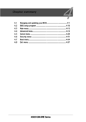
Chapter summary 4 4.1 Managing and updating your BIOS 4-1 4.2 BIOS setup program 4-10 4.3 Main menu 4-13 4.4 Advanced menu 4-19 4.5 Server menu 4-29 4.6 Security menu 4-31 4.7 Boot menu 4-34 4.8 Exit menu 4-37 ASUS K8N-DRE Series
Chapter summary 4 4.1 Managing and updating your BIOS 4-1 4.2 BIOS setup program 4-10 4.3 Main menu 4-13 4.4 Advanced menu 4-19 4.5 Server menu 4-29 4.6 Security menu 4-31 4.7 Boot menu 4-34 4.8 Exit menu 4-37 ASUS K8N-DRE Series
User Guide
Page 59
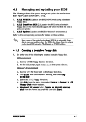
... F i l e from the Windows® desktop, then select M y C o m p u t e r. ASUS K8NDRE 4-1 Do either one of the original motherboard BIOS file to a bootable floppy disk in the future. d. e. A S U S C r a s h F r e e B I O S 2 (Updates the BIOS using a bootable floppy disk.) 2. A S U S A F U D O S (Updates the BIOS in Windows® environment.) Refer to the floppy disk drive. A S U S U p d a t e (Updates the BIOS in DOS mode using a bootable floppy disk or...
... F i l e from the Windows® desktop, then select M y C o m p u t e r. ASUS K8NDRE 4-1 Do either one of the original motherboard BIOS file to a bootable floppy disk in the future. d. e. A S U S C r a s h F r e e B I O S 2 (Updates the BIOS using a bootable floppy disk.) 2. A S U S A F U D O S (Updates the BIOS in Windows® environment.) Refer to the floppy disk drive. A S U S U p d a t e (Updates the BIOS in DOS mode using a bootable floppy disk or...
User Guide
Page 60
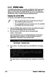
...you to copy the current BIOS file that the floppy disk is any user-assigned filename not more than eight alphanumeric characters for the main filename and three alphanumeric characters for reference only. Copy the AFUDOS utility (afudos.exe) from the motherboard support CD to file......... This utility also allows you created earlier. 2. The actual BIOS screen displays may not be same as backup when the BIOS fails or gets corrupted during the updating process. Version 1.19(ASUS V2.07(03.11.24BB)) Copyright ...
...you to copy the current BIOS file that the floppy disk is any user-assigned filename not more than eight alphanumeric characters for the main filename and three alphanumeric characters for reference only. Copy the AFUDOS utility (afudos.exe) from the motherboard support CD to file......... This utility also allows you created earlier. 2. The actual BIOS screen displays may not be same as backup when the BIOS fails or gets corrupted during the updating process. Version 1.19(ASUS V2.07(03.11.24BB)) Copyright ...

User Guide
Page 61
... boot failure! done Advance Check ...... The utility verifies the file and starts updating the BIOS. Boot the system in DOS mode, then at the DOS prompt. 2. Visit the ASUS website (www.asus.com) and download the latest BIOS file for the motherboard. done Reading flash ...... Erasing flash ...... done Writing flash ...... 0x0008CC00 (9%) Do not shut down...
... boot failure! done Advance Check ...... The utility verifies the file and starts updating the BIOS. Boot the system in DOS mode, then at the DOS prompt. 2. Visit the ASUS website (www.asus.com) and download the latest BIOS file for the motherboard. done Reading flash ...... Erasing flash ...... done Writing flash ...... 0x0008CC00 (9%) Do not shut down...
User Guide
Page 62
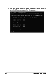
Version 1.19(ASUS V2.07(03.11.24BB)) Copyright (C) 2002 American Megatrends, Inc. done Writing flash ...... done Please restart your computer A:\> 4-4 Chapter 4: BIOS setup Reboot the system from the hard disk drive. All rights reserved. done Reading flash ...... Erasing flash ...... Do not turn off power during flash BIOS Reading file ....... done Advance Check ...... WARNING!! 5. done Verifying flash .... A:\>afudos /iK8NDRE.ROM /pbnc AMI Firmware Update Utility - The utility returns to the DOS prompt after the BIOS update process is completed.
Version 1.19(ASUS V2.07(03.11.24BB)) Copyright (C) 2002 American Megatrends, Inc. done Writing flash ...... done Please restart your computer A:\> 4-4 Chapter 4: BIOS setup Reboot the system from the hard disk drive. All rights reserved. done Reading flash ...... Erasing flash ...... Do not turn off power during flash BIOS Reading file ....... done Advance Check ...... WARNING!! 5. done Verifying flash .... A:\>afudos /iK8NDRE.ROM /pbnc AMI Firmware Update Utility - The utility returns to the DOS prompt after the BIOS update process is completed.
User Guide
Page 63
... floppy disk that contains the updated BIOS file. • Prepare the motherboard support CD or the floppy disk containing the updated motherboard BIOS before using this utility. • Make sure that allows you rename the original or updated BIOS file in the floppy disk to K 8 N D R E . 4.1.3 ASUS CrashFree BIOS 2 utility The ASUS CrashFree BIOS 2 is an auto recovery tool that...
... floppy disk that contains the updated BIOS file. • Prepare the motherboard support CD or the floppy disk containing the updated motherboard BIOS before using this utility. • Make sure that allows you rename the original or updated BIOS file in the floppy disk to K 8 N D R E . 4.1.3 ASUS CrashFree BIOS 2 utility The ASUS CrashFree BIOS 2 is an auto recovery tool that...


