
User Guide
Page 10
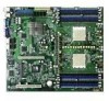
...JBOD configurations LSI 1020A SCSI RAID controller supports: - supports 2 ports) Special features ASUS Q-Fan 2 ASUS CrashFree BIOS 2 ASUS MyLogo2 Rear panel 1 x Serial port (COM1) 2 x LAN (RJ-45) ...ATX 12 V 2.0 compliant (continued on board; RAID 0, RAID 1, and RAID 1E configurations (SCSI model only) Dual LAN 2 x BROADCOM® BCM5721 Gigabit PCI-E LAN controllers USB 2 x USB 2.0 ports (on the rear panel) 1 x USB 2.0 connector (on the next page) x K8N-DRE...GB system memory (Note: Tested only up to 16 GB on this motherboard due to 2 GB DDR availability) 1 x PCI Express x16 slot 1...
...JBOD configurations LSI 1020A SCSI RAID controller supports: - supports 2 ports) Special features ASUS Q-Fan 2 ASUS CrashFree BIOS 2 ASUS MyLogo2 Rear panel 1 x Serial port (COM1) 2 x LAN (RJ-45) ...ATX 12 V 2.0 compliant (continued on board; RAID 0, RAID 1, and RAID 1E configurations (SCSI model only) Dual LAN 2 x BROADCOM® BCM5721 Gigabit PCI-E LAN controllers USB 2 x USB 2.0 ports (on the rear panel) 1 x USB 2.0 connector (on the next page) x K8N-DRE...GB system memory (Note: Tested only up to 16 GB on this motherboard due to 2 GB DDR availability) 1 x PCI Express x16 slot 1...
User Guide
Page 16
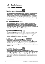
...Chapter 1: Product introduction Dual Channel DDR memory support Employing the Double Data Rate (DDR) memory technology, the motherboard supports up the PCI bus. The SATA 3Gb/s specification provides twice the bandwidth of ownership and development. Additionally, Serial ATA allows thinner, more flexible cables...protection, and reduced total cost of the current Serial ATA products. 1.3 Special features 1.3.1 Product highlights Latest processor technology The motherboard comes with dual 940-pin sockets for details. This high speed interface is a high-speed, low latency, point-to-point...
...Chapter 1: Product introduction Dual Channel DDR memory support Employing the Double Data Rate (DDR) memory technology, the motherboard supports up the PCI bus. The SATA 3Gb/s specification provides twice the bandwidth of ownership and development. Additionally, Serial ATA allows thinner, more flexible cables...protection, and reduced total cost of the current Serial ATA products. 1.3 Special features 1.3.1 Product highlights Latest processor technology The motherboard comes with dual 940-pin sockets for details. This high speed interface is a high-speed, low latency, point-to-point...

User Guide
Page 17
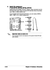
...ASUS K8N-DRE 1-3 See section "4.4.8 Hardware Monitor" on USB 2.0. Temperature, fan, and voltage monitoring The CPU temperature is backward compatible with dual-RAID functionality that allows you to prevent overheating and damage. See pages 2-22 and 2-27 for details. Dual RAID solution Onboard RAID controllers provide the motherboard... 2.0 technology The motherboard implements the Universal Serial Bus (USB) 2.0 specification, dramatically increasing the connection speed from the 12 Mbps bandwidth on USB 1.1 to ensure stable supply of current for four SATA and two PATA connectors...
...ASUS K8N-DRE 1-3 See section "4.4.8 Hardware Monitor" on USB 2.0. Temperature, fan, and voltage monitoring The CPU temperature is backward compatible with dual-RAID functionality that allows you to prevent overheating and damage. See pages 2-22 and 2-27 for details. Dual RAID solution Onboard RAID controllers provide the motherboard... 2.0 technology The motherboard implements the Universal Serial Bus (USB) 2.0 specification, dramatically increasing the connection speed from the 12 Mbps bandwidth on USB 1.1 to ensure stable supply of current for four SATA and two PATA connectors...
User Guide
Page 44
... installed. 2-24 Chapter 2: Hardware information SATA2 GND RSATA_TXP2 RSATA_TXN2 GND RSATA_RXN2 RSATA_RXP2 GND GND RSATA_TXP1 RSATA_TXN1 GND RSATA_RXN1 RSATA_RXP1 GND K8N-DRE ® SATA1 SATA4 GND RSATA_TXP4 RSATA_TXN4 GND RSATA_RXN4 RSATA_RXP4 GND K8N-DRE SATA connectors SATA3 GND RSATA_TXP3 RSATA_TXN3 GND RSATA_RXN3 RSATA_RXP3 GND Important notes on Serial ATA The actual data transfer rate depends...
... installed. 2-24 Chapter 2: Hardware information SATA2 GND RSATA_TXP2 RSATA_TXN2 GND RSATA_RXN2 RSATA_RXP2 GND GND RSATA_TXP1 RSATA_TXN1 GND RSATA_RXN1 RSATA_RXP1 GND K8N-DRE ® SATA1 SATA4 GND RSATA_TXP4 RSATA_TXN4 GND RSATA_RXN4 RSATA_RXP4 GND K8N-DRE SATA connectors SATA3 GND RSATA_TXP3 RSATA_TXN3 GND RSATA_RXN3 RSATA_RXP3 GND Important notes on Serial ATA The actual data transfer rate depends...

User Guide
Page 45
... causes the front panel LED to light up to the SCSI or SATA add-on card. K8N-DRE ® HDLED1 1 NC ADD_IN_CARD_ACT# ADD_IN_CARD_ACT# NC K8N-DRE Hard disk activity LED connector ASUS K8N-DRE 2-25 S C S I /O cell that supports both single-ended (SE), Ultra2, and Ultra160/320 devices. K8N-DRE ® 68 34 SCSI1 68-Pin Ultra320/ Ultra2-Wide SCSI Connector... of 12m (or 25m in a point-to an SE speed and 1.5m cable length. 5 . Storage add-on card cable connected to 160MB/s or 320MB/s) and extended cabling of 15 devices as specified by the Ultra160/320 standards.
... causes the front panel LED to light up to the SCSI or SATA add-on card. K8N-DRE ® HDLED1 1 NC ADD_IN_CARD_ACT# ADD_IN_CARD_ACT# NC K8N-DRE Hard disk activity LED connector ASUS K8N-DRE 2-25 S C S I /O cell that supports both single-ended (SE), Ultra2, and Ultra160/320 devices. K8N-DRE ® 68 34 SCSI1 68-Pin Ultra320/ Ultra2-Wide SCSI Connector... of 12m (or 25m in a point-to an SE speed and 1.5m cable length. 5 . Storage add-on card cable connected to 160MB/s or 320MB/s) and extended cabling of 15 devices as specified by the Ultra160/320 standards.

User Guide
Page 51
...-in card is read or write activities of any device connected to the SCSI or SATA add-in card causes this LED to this connector. ASUS K8N-DRE 2-31 The IDE LED lights up . • System warning speaker (Orange 4-pin SPKROUT) This 4-pin connector is in SLEEP or SOFT-...easy connection. NMIBTN# MLED+ GND MLED- Refer to this connector. System panel connector (20-pin PANEL1) This connector supports several chassis-mounted functions. K8N-DRE PANEL1 ® HDLED+ POWERLED+ HDLED- Pressing the power switch for more than four seconds while the system is ON turns the system OFF. &#...
...-in card is read or write activities of any device connected to the SCSI or SATA add-in card causes this LED to this connector. ASUS K8N-DRE 2-31 The IDE LED lights up . • System warning speaker (Orange 4-pin SPKROUT) This 4-pin connector is in SLEEP or SOFT-...easy connection. NMIBTN# MLED+ GND MLED- Refer to this connector. System panel connector (20-pin PANEL1) This connector supports several chassis-mounted functions. K8N-DRE PANEL1 ® HDLED+ POWERLED+ HDLED- Pressing the power switch for more than four seconds while the system is ON turns the system OFF. &#...

User Guide
Page 99
...disk drives is data mirroring and data striping combined. If one drive to a second drive. J B O D (Spanning) stands for details. ASUS K8N-DRE 5-1 This configuration uses two or more hard disk drives for this setup. Use two new drives or use three or more drives that you ... to read and write data in parallel, interleaved stacks. 5.1 Setting up RAID The motherboard comes with the following RAID solutions: • The N V I D I A® nForce Professional 2200 chipset comes with a built-in SATA RAID controller that allows you to configure RAID 0, RAID 1, RAID 1+0 and JBOD ...
...disk drives is data mirroring and data striping combined. If one drive to a second drive. J B O D (Spanning) stands for details. ASUS K8N-DRE 5-1 This configuration uses two or more hard disk drives for this setup. Use two new drives or use three or more drives that you ... to read and write data in parallel, interleaved stacks. 5.1 Setting up RAID The motherboard comes with the following RAID solutions: • The N V I D I A® nForce Professional 2200 chipset comes with a built-in SATA RAID controller that allows you to configure RAID 0, RAID 1, RAID 1+0 and JBOD ...

User Guide
Page 100
... cable to the SATA connector on each RAID controller. Connect the SCSI interface cable connectors at the back of each drive and to the power connector on the motherboard. 3. To install the SCSI hard disks for details on the motherboard. 5.1.3 RAID configuration utility You can use the N V I D I A® R A I D U t i l i t y if you can create a RAID...
... cable to the SATA connector on each RAID controller. Connect the SCSI interface cable connectors at the back of each drive and to the power connector on the motherboard. 3. To install the SCSI hard disks for details on the motherboard. 5.1.3 RAID configuration utility You can use the N V I D I A® R A I D U t i l i t y if you can create a RAID...

User Guide
Page 101
.... • Refer to set the necessary RAID items in the BIOS before setting your screen. Enter the BIOS Setup during POST. 2. ASUS K8N-DRE 5-3 5.2 NVIDIA® RAID configurations The motherboard includes a high performance SATA RAID controller integrated in this section are for reference only, and may not exactly match the items on your RAID configuration...
.... • Refer to set the necessary RAID items in the BIOS before setting your screen. Enter the BIOS Setup during POST. 2. ASUS K8N-DRE 5-3 5.2 NVIDIA® RAID configurations The motherboard includes a high performance SATA RAID controller integrated in this section are for reference only, and may not exactly match the items on your RAID configuration...

User Guide
Page 109
During POST, Press + to the next section for details. ASUS K8N-DRE 5-11 The LSI Logic Configuration Utility main menu appears. The LSI Logic Configuration Utility has two tabbed menus that you to create RAID 0, RAID 1, and ... by pressing . Refer to enter the LSI Logic Configuration Utility. To enter the LSI Logic Configuration Utility: 1. Turn on the system after installing all the SATA hard disk drives. 2. 5.3 LSI Logic Configuration Utility (SCSI model only) The LSI Logic Configuration Utility allows you can select by the LSI 1020A SCSI controller...
During POST, Press + to the next section for details. ASUS K8N-DRE 5-11 The LSI Logic Configuration Utility main menu appears. The LSI Logic Configuration Utility has two tabbed menus that you to create RAID 0, RAID 1, and ... by pressing . Refer to enter the LSI Logic Configuration Utility. To enter the LSI Logic Configuration Utility: 1. Turn on the system after installing all the SATA hard disk drives. 2. 5.3 LSI Logic Configuration Utility (SCSI model only) The LSI Logic Configuration Utility allows you can select by the LSI 1020A SCSI controller...
User Guide
Page 132
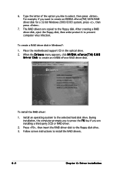
...I D D r i v e r D i s k to prevent computer virus infection. During installation, the computer prompts you to press the F 6 key if you are copied to create an NVIDIA nForce(TM) SATA RAID driver disk for a 32-bit Windows 2000/2003 system, press , then press . 7. After creating a RAID driver disk, eject the floppy disk, then write-protect.... 6-2 Chapter 6: Driver installation Press , then insert the RAID driver disk to select, then press . 6. Place the motherboard support CD in Windows®: 1. To install the RAID driver: 1. To create a RAID driver disk in the optical ...
...I D D r i v e r D i s k to prevent computer virus infection. During installation, the computer prompts you to press the F 6 key if you are copied to create an NVIDIA nForce(TM) SATA RAID driver disk for a 32-bit Windows 2000/2003 system, press , then press . 7. After creating a RAID driver disk, eject the floppy disk, then write-protect.... 6-2 Chapter 6: Driver installation Press , then insert the RAID driver disk to select, then press . 6. Place the motherboard support CD in Windows®: 1. To install the RAID driver: 1. To create a RAID driver disk in the optical ...


