
User Guide
Page 1
K8N-DRE Motherboard
K8N-DRE Motherboard

User Guide
Page 3
... Notices vi Safety information vii About this guide viii Typography ix K8N-DRE specifications summary x Chapter 1: Product introduction 1.1 Welcome 1-1 1.2 Package contents 1-1 1.3 Special features 1-2 1.3.1 Product highlights 1-2 1.3.2 Innovative ASUS features 1-4 Chapter 2: Hardware information 2.1 Before you proceed 2-1 Onboard LEDs 2-1 2.2 Motherboard overview 2-2 2.2.1 Placement direction 2-2 2.2.2 Screw holes 2-2 2.2.3 Motherboard layout 2-3 2.2.4 Heatsink plates 2-4 2.2.5 Layout Contents 2-7 2.3 Central Processing Unit (CPU 2-9 2.3.1 Overview 2-9 2.3.2 Installing...
... Notices vi Safety information vii About this guide viii Typography ix K8N-DRE specifications summary x Chapter 1: Product introduction 1.1 Welcome 1-1 1.2 Package contents 1-1 1.3 Special features 1-2 1.3.1 Product highlights 1-2 1.3.2 Innovative ASUS features 1-4 Chapter 2: Hardware information 2.1 Before you proceed 2-1 Onboard LEDs 2-1 2.2 Motherboard overview 2-2 2.2.1 Placement direction 2-2 2.2.2 Screw holes 2-2 2.2.3 Motherboard layout 2-3 2.2.4 Heatsink plates 2-4 2.2.5 Layout Contents 2-7 2.3 Central Processing Unit (CPU 2-9 2.3.1 Overview 2-9 2.3.2 Installing...

User Guide
Page 7
...in any damage, contact your dealer immediately. • To avoid short circuits, keep paper clips, screws, and staples away from the motherboard, ensure that came with the product, contact a qualified service technician or your local power company. • If the power supply ..., make sure all power cables are not damaged. vii Contact a qualified service technician or your area. Operation safety • Before installing the motherboard and adding devices on a stable surface. • If you add a device. • Before connecting or removing signal cables from connectors, ...
...in any damage, contact your dealer immediately. • To avoid short circuits, keep paper clips, screws, and staples away from the motherboard, ensure that came with the product, contact a qualified service technician or your local power company. • If the power supply ..., make sure all power cables are not damaged. vii Contact a qualified service technician or your area. Operation safety • Before installing the motherboard and adding devices on a stable surface. • If you add a device. • Before connecting or removing signal cables from connectors, ...
User Guide
Page 8
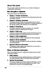
...1: Product introduction This chapter describes the features of the switches, jumpers, and connectors on ASUS hardware and software products. It includes description of the motherboard and the new technology it supports. • Chapter 2: Hardware information This chapter lists ...sources for additional information and for this motherboard. • Appendix: Reference information This appendix includes additional information that may refer to when configuring the motherboard. ASUS websites The ASUS website provides updated information on the motherboard. • Chapter 3: Powering up ...
...1: Product introduction This chapter describes the features of the switches, jumpers, and connectors on ASUS hardware and software products. It includes description of the motherboard and the new technology it supports. • Chapter 2: Hardware information This chapter lists ...sources for additional information and for this motherboard. • Appendix: Reference information This appendix includes additional information that may refer to when configuring the motherboard. ASUS websites The ASUS website provides updated information on the motherboard. • Chapter 3: Powering up ...

User Guide
Page 10
...8-pin 12 V plugs) ATX 12 V 2.0 compliant (continued on board; RAID 0, RAID 1, and RAID 1E configurations (SCSI model only) Dual LAN 2 x BROADCOM® BCM5721 Gigabit PCI-E LAN controllers USB 2 x USB 2.0 ports (on the rear panel) 1 x USB 2.0 connector (on the next page) x K8N-DRE specifications summary CPU Chipset System... registered ECC 400/333/266 MHz DDR memory modules Supports up to 32 GB system memory (Note: Tested only up to 16 GB on this motherboard due to 2 GB DDR availability) 1 x PCI Express x16 slot 1 x PCI slot NVIDIA® nForce Professional 2200 chipset supports: - 2 x...
...8-pin 12 V plugs) ATX 12 V 2.0 compliant (continued on board; RAID 0, RAID 1, and RAID 1E configurations (SCSI model only) Dual LAN 2 x BROADCOM® BCM5721 Gigabit PCI-E LAN controllers USB 2 x USB 2.0 ports (on the rear panel) 1 x USB 2.0 connector (on the next page) x K8N-DRE specifications summary CPU Chipset System... registered ECC 400/333/266 MHz DDR memory modules Supports up to 32 GB system memory (Note: Tested only up to 16 GB on this motherboard due to 2 GB DDR availability) 1 x PCI Express x16 slot 1 x PCI slot NVIDIA® nForce Professional 2200 chipset supports: - 2 x...

User Guide
Page 13
This chapter describes the motherboard features and the new technologies it supports. 1Product introduction
This chapter describes the motherboard features and the new technologies it supports. 1Product introduction

User Guide
Page 15
...standout in the long line of the above items is damaged or missing, contact your motherboard package for the following items. Motherboard Cables Accessories Application CD Documentation ASUS K8N-DRE motherboard 4 x Serial ATA signal cables (dual plugs) 2 x Serial ATA power cables ... below. 1.2 Package contents Check your retailer. The motherboard delivers a host of new features and latest technologies, making it , check the items in -1 IDE and floppy cable I/O shield 2 x Copper heatsink 2 x Support plates for buying an ASUS® K8N-DRE motherboard! ASUS K8N-DRE 1-1 1.1 Welcome!
...standout in the long line of the above items is damaged or missing, contact your motherboard package for the following items. Motherboard Cables Accessories Application CD Documentation ASUS K8N-DRE motherboard 4 x Serial ATA signal cables (dual plugs) 2 x Serial ATA power cables ... below. 1.2 Package contents Check your retailer. The motherboard delivers a host of new features and latest technologies, making it , check the items in -1 IDE and floppy cable I/O shield 2 x Copper heatsink 2 x Support plates for buying an ASUS® K8N-DRE motherboard! ASUS K8N-DRE 1-1 1.1 Welcome!
User Guide
Page 16
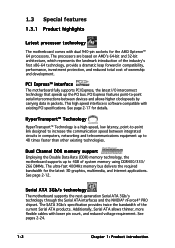
...applications. Dual Channel DDR memory support Employing the Double Data Rate (DDR) memory technology, the motherboard supports up to 48 times faster than other existing technologies. Serial ATA 3Gb/s technology The motherboard supports the next-generation Serial ATA 3Gb/s technology through the Serial ATA interfaces and the NVIDIA...; Technology is software compatible with lower pin count, and reduced voltage requirement. 1.3 Special features 1.3.1 Product highlights Latest processor technology The motherboard comes with dual 940-pin sockets for the AMD Opteron™ 64 processors.
...applications. Dual Channel DDR memory support Employing the Double Data Rate (DDR) memory technology, the motherboard supports up to 48 times faster than other existing technologies. Serial ATA 3Gb/s technology The motherboard supports the next-generation Serial ATA 3Gb/s technology through the Serial ATA interfaces and the NVIDIA...; Technology is software compatible with lower pin count, and reduced voltage requirement. 1.3 Special features 1.3.1 Product highlights Latest processor technology The motherboard comes with dual 940-pin sockets for the AMD Opteron™ 64 processors.

User Guide
Page 17
... fan rotations per minute (RPM) is monitored for details. See section "4.4.8 Hardware Monitor" on USB 2.0. USB 2.0 technology The motherboard implements the Universal Serial Bus (USB) 2.0 specification, dramatically increasing the connection speed from the 12 Mbps bandwidth on USB 1.1 to... solution Onboard RAID controllers provide the motherboard with USB 1.1. The NVIDIA® nForce4® PRO allows RAID 0, RAID 1, RAID 0+1 and JBOD configuration for details. The ASIC monitors the voltage levels to prevent overheating and damage. ASUS K8N-DRE 1-3 USB 2.0 is monitored by the...
... fan rotations per minute (RPM) is monitored for details. See section "4.4.8 Hardware Monitor" on USB 2.0. USB 2.0 technology The motherboard implements the Universal Serial Bus (USB) 2.0 specification, dramatically increasing the connection speed from the 12 Mbps bandwidth on USB 1.1 to... solution Onboard RAID controllers provide the motherboard with USB 1.1. The NVIDIA® nForce4® PRO allows RAID 0, RAID 1, RAID 0+1 and JBOD configuration for details. The ASIC monitors the voltage levels to prevent overheating and damage. ASUS K8N-DRE 1-3 USB 2.0 is monitored by the...
User Guide
Page 18
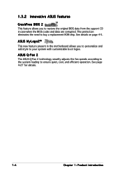
...technology smartly adjusts the fan speeds according to the system loading to your system with customizable boot logos. See details on page 4-5. ASUS MyLogo2™ This new feature present in case when the BIOS codes and data are corrupted. See page 4-27 for details. ... 1: Product introduction This protection eliminates the need to restore the original BIOS data from the support CD in the motherboard allows you to buy a replacement ROM chip. 1.3.2 Innovative ASUS features CrashFree BIOS 2 This feature allows you to personalize and add style to ensure quiet, cool, and efficient ...
...technology smartly adjusts the fan speeds according to the system loading to your system with customizable boot logos. See details on page 4-5. ASUS MyLogo2™ This new feature present in case when the BIOS codes and data are corrupted. See page 4-27 for details. ... 1: Product introduction This protection eliminates the need to restore the original BIOS data from the support CD in the motherboard allows you to buy a replacement ROM chip. 1.3.2 Innovative ASUS features CrashFree BIOS 2 This feature allows you to personalize and add style to ensure quiet, cool, and efficient ...

User Guide
Page 19
It includes description of the jumpers and connectors on the motherboard. 2 Hardware information This chapter lists the hardware setup procedures that you have to perform when installing system components.
It includes description of the jumpers and connectors on the motherboard. 2 Hardware information This chapter lists the hardware setup procedures that you have to perform when installing system components.

User Guide
Page 20
Chapter summary 2.1 Before you proceed 2-1 2.2 Motherboard overview 2-2 2.3 Central Processing Unit (CPU 2-9 2.4 System memory 2-12 2.5 Expansion slots 2-16 2.6 Jumpers 2-18 2.7 Connectors 2-22 ASUS K8N-DRE
Chapter summary 2.1 Before you proceed 2-1 2.2 Motherboard overview 2-2 2.3 Central Processing Unit (CPU 2-9 2.4 System memory 2-12 2.5 Expansion slots 2-16 2.6 Jumpers 2-18 2.7 Connectors 2-22 ASUS K8N-DRE

User Guide
Page 21
...power LED (SB_PWR1) The motherboard comes with the component. • Before you install or remove any component, place it on socket CPU1 CPU types mismatched OFF No detected CPU problem K8N-DRE Standby power LED SB_PWR1 ON Standby Power OFF Powered Off ASUS K8N-DRE 2-1 CPU warning LED (CPU_WARN1...) The CPU warning LED lights up to the motherboard, peripherals, and/or components. Onboard LEDs 1. CPU_WARN1 K8N-DRE ® ON No CPU installed No CPU on a grounded antistatic pad or in the bag that the ATX power supply is...
...power LED (SB_PWR1) The motherboard comes with the component. • Before you install or remove any component, place it on socket CPU1 CPU types mismatched OFF No detected CPU problem K8N-DRE Standby power LED SB_PWR1 ON Standby Power OFF Powered Off ASUS K8N-DRE 2-1 CPU warning LED (CPU_WARN1...) The CPU warning LED lights up to the motherboard, peripherals, and/or components. Onboard LEDs 1. CPU_WARN1 K8N-DRE ® ON No CPU installed No CPU on a grounded antistatic pad or in the bag that the ATX power supply is...

User Guide
Page 22
... Place ten (10) screws into the holes indicated by circles to secure the motherboard to do so can damage the motherboard. Do not overtighten the screws! Make sure to the rear part of the chassis K8N-DRE ® 2-2 Chapter 2: Hardware information The edge with external ports goes to ...unplug the power cord before installing or removing the motherboard. Place this side towards ...
... Place ten (10) screws into the holes indicated by circles to secure the motherboard to do so can damage the motherboard. Do not overtighten the screws! Make sure to the rear part of the chassis K8N-DRE ® 2-2 Chapter 2: Hardware information The edge with external ports goes to ...unplug the power cord before installing or removing the motherboard. Place this side towards ...

User Guide
Page 24
These plates support the weight of the adhesive pad with the heatsink plate standoffs. Peel off the adhesive pads that came with the motherboard package. Press the adhesive pad flat on the heatsink plate. 2-4 Chapter 2: Hardware information To install the heatsink plates: 1. Standoffs 3. 2.2.4 Heatsink plates Two heatsink plates come with the motherboard package. Match the holes of the CPU heatsinks. Adhesive pad 2.
These plates support the weight of the adhesive pad with the heatsink plate standoffs. Peel off the adhesive pads that came with the motherboard package. Press the adhesive pad flat on the heatsink plate. 2-4 Chapter 2: Hardware information To install the heatsink plates: 1. Standoffs 3. 2.2.4 Heatsink plates Two heatsink plates come with the motherboard package. Match the holes of the CPU heatsinks. Adhesive pad 2.

User Guide
Page 25
Position the heatsink plate underneath the motherboard and match the motherboard CPU1 heatsink holes with the heatsink plate standoffs. 7. ASUS K8N-DRE 2-5 Press the heatsink plate flat under the motherboard. Peel off the adhesive pad cover. 5. 4. Locate the heatsink holes on the motherboard. 6.
Position the heatsink plate underneath the motherboard and match the motherboard CPU1 heatsink holes with the heatsink plate standoffs. 7. ASUS K8N-DRE 2-5 Press the heatsink plate flat under the motherboard. Peel off the adhesive pad cover. 5. 4. Locate the heatsink holes on the motherboard. 6.

User Guide
Page 26
Even if you are not installing a second processor now, we recommend that you want to section "2.2.2 Screw Holes" for the illustration. 2-6 Chapter 2: Hardware information The heatsink plate standoffs appears as shown when installed. Standoffs 8. Refer to install a second processor in CPU2 socket. Secure the motherboard with ten (10) screws. Repeat steps 1-7 if you install the second heatsink plate. 9.
Even if you are not installing a second processor now, we recommend that you want to section "2.2.2 Screw Holes" for the illustration. 2-6 Chapter 2: Hardware information The heatsink plate standoffs appears as shown when installed. Standoffs 8. Refer to install a second processor in CPU2 socket. Secure the motherboard with ten (10) screws. Repeat steps 1-7 if you install the second heatsink plate. 9.
User Guide
Page 29
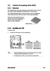
...of the notched corner on the motherboard. Locate the CPU socket on the CPU. This corner should match a specific corner on your left. • If installing only one CPU, use the CPU socket marked CPU1. K8N-DRE ® CPU2 CPU1 CPU2 CPU1 K8N-DRE CPU Socket 940 • ...sure that the socket box is facing towards you and the load lever is on the socket to ensure correct installation. ASUS K8N-DRE 2-9 2.3 Central Processing Unit (CPU) 2.3.1 Overview The motherboard comes with only 32-bit or 64-bit wide data paths. Notched corner 2.3.2 Installing the CPU To install a CPU:...
...of the notched corner on the motherboard. Locate the CPU socket on the CPU. This corner should match a specific corner on your left. • If installing only one CPU, use the CPU socket marked CPU1. K8N-DRE ® CPU2 CPU1 CPU2 CPU1 K8N-DRE CPU Socket 940 • ...sure that the socket box is facing towards you and the load lever is on the socket to ensure correct installation. ASUS K8N-DRE 2-9 2.3 Central Processing Unit (CPU) 2.3.1 Overview The motherboard comes with only 32-bit or 64-bit wide data paths. Notched corner 2.3.2 Installing the CPU To install a CPU:...
User Guide
Page 32
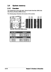
The following figure illustrates the location of the sockets: K8N-DRE ® DIMM_A1 DIMM_A2 DIMM_B1 DIMM_B2 DIMM_D2 DIMM_D1 DIMM_C2 DIMM_C1 104 Pins 80 Pins 80 Pins 104 Pins K8N-DRE 184-pin DDR DIMM sockets For CPU 1 Channel A Channel B For CPU 2 Channel A Channel B Sockets DIMM_A1 and DIMM_A2 DIMM_B1 and DIMM_B2 Sockets DIMM_C1 and DIMM_C2 DIMM_D1 and DIMM_D2 2-12 Chapter 2: Hardware information 2.4 System memory 2.4.1 Overview The motherboard comes with eight 184-pin Double Data Rate (DDR) Dual Inline Memory Modules (DIMM) sockets.
The following figure illustrates the location of the sockets: K8N-DRE ® DIMM_A1 DIMM_A2 DIMM_B1 DIMM_B2 DIMM_D2 DIMM_D1 DIMM_C2 DIMM_C1 104 Pins 80 Pins 80 Pins 104 Pins K8N-DRE 184-pin DDR DIMM sockets For CPU 1 Channel A Channel B For CPU 2 Channel A Channel B Sockets DIMM_A1 and DIMM_A2 DIMM_B1 and DIMM_B2 Sockets DIMM_C1 and DIMM_C2 DIMM_D1 and DIMM_D2 2-12 Chapter 2: Hardware information 2.4 System memory 2.4.1 Overview The motherboard comes with eight 184-pin Double Data Rate (DDR) Dual Inline Memory Modules (DIMM) sockets.

User Guide
Page 35
... socket. ASUS K8N-DRE 2-15 2.4.3 Installing a DIMM Make sure to remove a DIMM. 2 1. Failure to do so may cause severe damage to unlock the DIMM. 1 1 DDR DIMM notch Support the DIMM lightly with extra force. 2. Unlock a DIMM socket by pressing the retaining clips outward. 2. Simultaneously press the retaining clips outward to both the motherboard and...
... socket. ASUS K8N-DRE 2-15 2.4.3 Installing a DIMM Make sure to remove a DIMM. 2 1. Failure to do so may cause severe damage to unlock the DIMM. 1 1 DDR DIMM notch Support the DIMM lightly with extra force. 2. Unlock a DIMM socket by pressing the retaining clips outward. 2. Simultaneously press the retaining clips outward to both the motherboard and...


