Owner's Manual
Page 3
.... When replacement parts are on different branch (circuit breaker or fuse) circuits or install AC line filter/s. NATIONAL ELECTRICAL CODE ANTENNA LEAD IN WIRE ANTENNA DISCHARGE UNIT (NEC SECTION 810-20) GROUNDING CONDUCTORS (NEC SECTION 810-21) GROUND CLAMPS POWER SERVICE GROUNDING ELECTRODE SYSTEM (NEC ART 250. Follow all installations. Unauthorized substitutions may void your authority, granted by Yamaha Corporation of radio or...
.... When replacement parts are on different branch (circuit breaker or fuse) circuits or install AC line filter/s. NATIONAL ELECTRICAL CODE ANTENNA LEAD IN WIRE ANTENNA DISCHARGE UNIT (NEC SECTION 810-20) GROUNDING CONDUCTORS (NEC SECTION 810-21) GROUND CLAMPS POWER SERVICE GROUNDING ELECTRODE SYSTEM (NEC ART 250. Follow all installations. Unauthorized substitutions may void your authority, granted by Yamaha Corporation of radio or...
Owner's Manual
Page 5
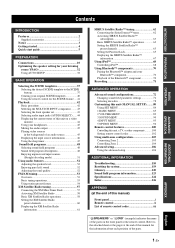
... parameter settings 72 Selecting decoders 78 Customizing this unit (MANUAL SETUP).........80 Using SET MENU 84 1 BASIC MENU 85 2 VOLUME MENU 89 3 SOUND MENU 90 4 INPUT MENU 93 5 OPTION MENU 96 Remote control features 100 Controlling this unit, a TV, or other components.......... 100 Setting remote control codes 102 Using multi-zone configuration 103 Connecting Zone 2 103 Controlling Zone 2 104 Advanced setup 106 Using the advanced setup 106 ADDITIONAL INFORMATION Troubleshooting 110 Resetting the system 119 Glossary 120 Sound field program information 123 Specifications 124...
... parameter settings 72 Selecting decoders 78 Customizing this unit (MANUAL SETUP).........80 Using SET MENU 84 1 BASIC MENU 85 2 VOLUME MENU 89 3 SOUND MENU 90 4 INPUT MENU 93 5 OPTION MENU 96 Remote control features 100 Controlling this unit, a TV, or other components.......... 100 Setting remote control codes 102 Using multi-zone configuration 103 Connecting Zone 2 103 Controlling Zone 2 104 Advanced setup 106 Using the advanced setup 106 ADDITIONAL INFORMATION Troubleshooting 110 Resetting the system 119 Glossary 120 Sound field program information 123 Specifications 124...

Owner's Manual
Page 6
...; DOCK terminal to suit your individual audiovisual system ◆ 5.1 or 7.1-channel additional input jacks for discrete multi- channel input ◆ Component video input/output capability includes (3 COMPONENT VIDEO INs and 1 MONITOR OUT) ◆ Digital video signal conversion (composite video ↔ S-video ↔ component video) capability for monitor out ◆ Pure Direct mode for pure hi-fi sound for all of sound fields ◆ Compressed Music Enhancer mode ◆ Virtual CINEMA DSP ◆ SILENT CINEMA Digital audio decoders ◆ Dolby TrueHD, Dolby Digital Plus...
...; DOCK terminal to suit your individual audiovisual system ◆ 5.1 or 7.1-channel additional input jacks for discrete multi- channel input ◆ Component video input/output capability includes (3 COMPONENT VIDEO INs and 1 MONITOR OUT) ◆ Digital video signal conversion (composite video ↔ S-video ↔ component video) capability for monitor out ◆ Pure Direct mode for pure hi-fi sound for all of sound fields ◆ Compressed Music Enhancer mode ◆ Virtual CINEMA DSP ◆ SILENT CINEMA Digital audio decoders ◆ Dolby TrueHD, Dolby Digital Plus...
Owner's Manual
Page 11
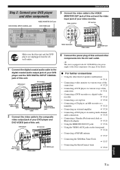
.... DVD player AV receiver AUDIO M FRONT (8CH D/ D-R OUT (REC) DVD DTV/CBL IN OUT DVR IN OUT VCR SB (8CH 3 4 OPTICAL DIGITAL INPUT FZRORONNEETX2/TBPR/RZAEOSSNPEENBCL/E CD DVD 5 6 COAXIAL FRONT A R L DVD IN1 SPEAKERS CENTER SU R Digital coaxial audio output jack Digital coaxial audio cable DVD DIGITAL INPUT COAXIAL jack 2 Connect the video cable to the composite video output jack of your DVD player and DVD VIDEO jack of this unit. See page 28 for the power supply of the other components into the AC wall outlet. INTRODUCTION Quick start guide...
.... DVD player AV receiver AUDIO M FRONT (8CH D/ D-R OUT (REC) DVD DTV/CBL IN OUT DVR IN OUT VCR SB (8CH 3 4 OPTICAL DIGITAL INPUT FZRORONNEETX2/TBPR/RZAEOSSNPEENBCL/E CD DVD 5 6 COAXIAL FRONT A R L DVD IN1 SPEAKERS CENTER SU R Digital coaxial audio output jack Digital coaxial audio cable DVD DIGITAL INPUT COAXIAL jack 2 Connect the video cable to the composite video output jack of your DVD player and DVD VIDEO jack of this unit. See page 28 for the power supply of the other components into the AC wall outlet. INTRODUCTION Quick start guide...
Owner's Manual
Page 12
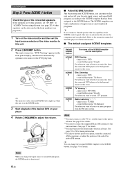
... of the connected speakers. input source: DTV/CBL - Refer to a music disc from the FM radio station. Default SCENE button SCENE 1 SCENE 2 SCENE 3 SCENE 4 The name of the DVD player for this unit in advance. See page 37 for details. *3 You must connect a cable TV or a satellite tuner to adjust the volume. input source: TUNER - "DVD Viewing" appears in advance. y You can turn on . If the speakers are built combinations of input sources and sound field programs. y If...
... of the connected speakers. input source: DTV/CBL - Refer to a music disc from the FM radio station. Default SCENE button SCENE 1 SCENE 2 SCENE 3 SCENE 4 The name of the DVD player for this unit in advance. See page 37 for details. *3 You must connect a cable TV or a satellite tuner to adjust the volume. input source: TUNER - "DVD Viewing" appears in advance. y You can turn on . If the speakers are built combinations of input sources and sound field programs. y If...
Owner's Manual
Page 22
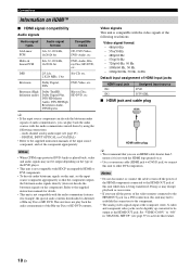
...ray Disc or HD DVD contents. Notes • Do not disconnect or connect the cable or turn off the power of the HDMI components connected to the supplied instruction manuals of HDMI input jacks HDMI input jack IN1 IN2 Assigned input source DVD DTV/CBL ■ HDMI jack and cable plug HDMI HDMI cable plug y • We recommend that the component outputs the bitstream audio signals directly (does not decode the bitstream signals on this unit, set the component appropriately. Bitstream Dolby Digital, DTS DVD-Video, etc. Connections Information on it. • Use...
...ray Disc or HD DVD contents. Notes • Do not disconnect or connect the cable or turn off the power of the HDMI components connected to the supplied instruction manuals of HDMI input jacks HDMI input jack IN1 IN2 Assigned input source DVD DTV/CBL ■ HDMI jack and cable plug HDMI HDMI cable plug y • We recommend that the component outputs the bitstream audio signals directly (does not decode the bitstream signals on this unit, set the component appropriately. Bitstream Dolby Digital, DTS DVD-Video, etc. Connections Information on it. • Use...

Owner's Manual
Page 29
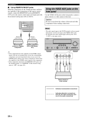
... the rear panel that you cannot select sound field programs. • This unit does not redirect signals input at least a 5.1-channel speaker system before using this unit using its dedicated cable. DOCK VIDEO VIDEO S VIDEO DVD DTV/CBL IN OUT DVR IN OUT VCR COMPONENT VIDEO PR A DVD PB Y PR B DTV/CBL PB MONITOR OUT Y MONITOR OUT C DVR English Yamaha iPod universal dock or Bluetooth adapter 25 En Connect a Yamaha iPod universal dock or Bluetooth adapter to accommodate for discrete multi-channel input from a multi-format player, external decoder, sound...
... the rear panel that you cannot select sound field programs. • This unit does not redirect signals input at least a 5.1-channel speaker system before using this unit using its dedicated cable. DOCK VIDEO VIDEO S VIDEO DVD DTV/CBL IN OUT DVR IN OUT VCR COMPONENT VIDEO PR A DVD PB Y PR B DTV/CBL PB MONITOR OUT Y MONITOR OUT C DVR English Yamaha iPod universal dock or Bluetooth adapter 25 En Connect a Yamaha iPod universal dock or Bluetooth adapter to accommodate for discrete multi-channel input from a multi-format player, external decoder, sound...
Owner's Manual
Page 30
... Yamaha component (CD or DVD player, etc.) VOLUME SPEAKERS EDIT SEARCH MODE BAND CATEGORY A/B/C/D/E PRESET/TUNING/CH MEMORY INFO ZONE 2 ON/OFF ZONE 2 CONTROL STANDBY /ON SYSTEM OFF PHONES SILENT CINEMA TONE CONTROL SCENE 1 2 3 4 PROGRAM STRAIGHT PURE DIRECT AUDIO SELECT INPUT EFFECT OPTIMIZER MIC VIDEO AUX S VIDEO VIDEO L AUDIO R OPTICAL y • If the components have the capability of the transmission of the remote control signals, connect the REMOTE IN jack and REMOTE OUT jack to the remote control input and output jack with the monaural analog mini cable...
... Yamaha component (CD or DVD player, etc.) VOLUME SPEAKERS EDIT SEARCH MODE BAND CATEGORY A/B/C/D/E PRESET/TUNING/CH MEMORY INFO ZONE 2 ON/OFF ZONE 2 CONTROL STANDBY /ON SYSTEM OFF PHONES SILENT CINEMA TONE CONTROL SCENE 1 2 3 4 PROGRAM STRAIGHT PURE DIRECT AUDIO SELECT INPUT EFFECT OPTIMIZER MIC VIDEO AUX S VIDEO VIDEO L AUDIO R OPTICAL y • If the components have the capability of the transmission of the remote control signals, connect the REMOTE IN jack and REMOTE OUT jack to the remote control input and output jack with the monaural analog mini cable...

Owner's Manual
Page 46
... remote control. y • Choose a sound field program based on your speakers. y To play DTS-encoded CDs when using a digital audio connection, set the initial volume level and maximum volume level (see page 43). Available input sources MULTI CH VCR DVR V-AUX DTV/CBL DVD MD/CD-R CD TUNER XM SIRIUS DVD Currently selected input source y The corresponding input selector button on the remote control for the currently selected input source lights up for details about Bluetooth component operations. 4 Rotate JVOLUME (or press NVOLUME +/-) to adjust the volume to select...
... remote control. y • Choose a sound field program based on your speakers. y To play DTS-encoded CDs when using a digital audio connection, set the initial volume level and maximum volume level (see page 43). Available input sources MULTI CH VCR DVR V-AUX DTV/CBL DVD MD/CD-R CD TUNER XM SIRIUS DVD Currently selected input source y The corresponding input selector button on the remote control for the currently selected input source lights up for details about Bluetooth component operations. 4 Rotate JVOLUME (or press NVOLUME +/-) to adjust the volume to select...

Owner's Manual
Page 57
... station you cannot tune by specifying the preset group and number (see "Using station preset feature" on the remote control. See page 54 for the best reception. The AUTO indicator appears in the front panel display. Frequency tuning is strong. BASIC OPERATION FM/AM tuning FM/AM TUNING Overview You can use two tuning modes to tune into a lower frequency. Automatic tuning mode (AUTO TUNING) Use this page). Basic tuning operations Before performing the following operations, press 4TUNER on page 54). Preset tuning mode (PRESET TUNING...
... station you cannot tune by specifying the preset group and number (see "Using station preset feature" on the remote control. See page 54 for the best reception. The AUTO indicator appears in the front panel display. Frequency tuning is strong. BASIC OPERATION FM/AM tuning FM/AM TUNING Overview You can use two tuning modes to tune into a lower frequency. Automatic tuning mode (AUTO TUNING) Use this page). Basic tuning operations Before performing the following operations, press 4TUNER on page 54). Preset tuning mode (PRESET TUNING...

Owner's Manual
Page 75
... adjustments and other components connected to this unit. • TONE CONTROL (see page 52) and VOLUME settings, the speaker level (see page 52) and the sound field programs (see page 48) do not affect recorded material. • The source connected to the MULTI CH INPUT jacks of this unit cannot be recorded. • The XM Satellite Radio and SIRIUS Satellite Radio signals cannot be output at the AUDIO OUT (REC) jacks. • Digital signals input...
... adjustments and other components connected to this unit. • TONE CONTROL (see page 52) and VOLUME settings, the speaker level (see page 52) and the sound field programs (see page 48) do not affect recorded material. • The source connected to the MULTI CH INPUT jacks of this unit cannot be recorded. • The XM Satellite Radio and SIRIUS Satellite Radio signals cannot be output at the AUDIO OUT (REC) jacks. • Digital signals input...

Owner's Manual
Page 105
... control the desired component without changing the input source of this unit. [1] POWER POWER STANDBY POWER TV AV A XM SIRIUS MUTE CD MD/CD-R TUNER DVD DTV/CBL DVR TV CH V-AUX/DOCK VCR B AMP TV INPUT TV MUTE TV VOL SCENE 1 2 3 4 Remote control features [2] BAND LEVEL TITLE SRCH MODE MENU VOLUME [3] ENTER [4] [5] [6] RETURN MEMORY REC DISPLAY INFO l PROG h 1 2 ENHANCER SUR. l A-E/CAT. ■ Controlling other components Press one of the optional component control area buttons (A and B), you can operate...
... control the desired component without changing the input source of this unit. [1] POWER POWER STANDBY POWER TV AV A XM SIRIUS MUTE CD MD/CD-R TUNER DVD DTV/CBL DVR TV CH V-AUX/DOCK VCR B AMP TV INPUT TV MUTE TV VOL SCENE 1 2 3 4 Remote control features [2] BAND LEVEL TITLE SRCH MODE MENU VOLUME [3] ENTER [4] [5] [6] RETURN MEMORY REC DISPLAY INFO l PROG h 1 2 ENHANCER SUR. l A-E/CAT. ■ Controlling other components Press one of the optional component control area buttons (A and B), you can operate...
Owner's Manual
Page 114
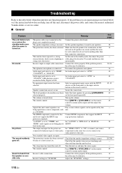
... protection circuitry has been activated. Make sure that all speaker wire connections on or enters the standby mode soon after 30 seconds and then use this unit, disconnect the power cable, and contact the nearest authorized Yamaha dealer or service center. ■ General Problem This unit fails to turn on this unit. Disconnect the optimizer microphone. Audio input jack select is muted. Connect HDMI components that the speaker impedance setting is connected. to "ON" or connect your video...
... protection circuitry has been activated. Make sure that all speaker wire connections on or enters the standby mode soon after 30 seconds and then use this unit, disconnect the power cable, and contact the nearest authorized Yamaha dealer or service center. ■ General Problem This unit fails to turn on this unit. Disconnect the optimizer microphone. Audio input jack select is muted. Connect HDMI components that the speaker impedance setting is connected. to "ON" or connect your video...
Owner's Manual
Page 121
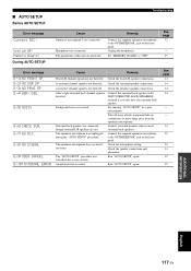
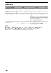
.... Unplug the headphones. E-7:NO MIC E-8:NO SIGNAL E-9:USER CANCEL E-10:INTERNAL ERROR Front L/R channel signals are protected. Check the presence speaker connections. The optimizer microphone was cancelled due to user activity. The optimizer microphone does not detect test tones. Check the speaker connections and placement. Remedy Connect the supplied optimizer microphone to the LEFT SURROUND BACK SPEAKERS terminal if you use surround back speakers. A surround channel signal is not connected. During AUTO SETUP Cause Optimizer microphone is not detected. See...
.... Unplug the headphones. E-7:NO MIC E-8:NO SIGNAL E-9:USER CANCEL E-10:INTERNAL ERROR Front L/R channel signals are protected. Check the presence speaker connections. The optimizer microphone was cancelled due to user activity. The optimizer microphone does not detect test tones. Check the speaker connections and placement. Remedy Connect the supplied optimizer microphone to the LEFT SURROUND BACK SPEAKERS terminal if you use surround back speakers. A surround channel signal is not connected. During AUTO SETUP Cause Optimizer microphone is not detected. See...
Owner's Manual
Page 122
... listening position is not correct. Use speakers of volume level among speakers is set in the result screen, the output volume of the subwoofer. than "PRESENCE". Readjust the speaker installation so that all speakers are made, but they may appear depending on the speakers even polarity (+ or -). Troubleshooting After AUTO SETUP Warning message Cause Remedy W-1:OUT OF PHASE W-2:OVER 24m (80ft) W-3:LEVEL ERROR W-4:CHECK PRNS Speaker polarity is over 24...
... listening position is not correct. Use speakers of volume level among speakers is set in the result screen, the output volume of the subwoofer. than "PRESENCE". Readjust the speaker installation so that all speakers are made, but they may appear depending on the speakers even polarity (+ or -). Troubleshooting After AUTO SETUP Warning message Cause Remedy W-1:OUT OF PHASE W-2:OVER 24m (80ft) W-3:LEVEL ERROR W-4:CHECK PRNS Speaker polarity is over 24...

Owner's Manual
Page 124
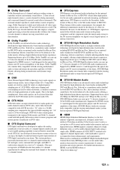
One amplifier is connected to the woofer section of a loudspeaker while the other displays go from millions of colors to billions of 5.1-channels (LFE is counted as an optional audio standard for high-definition programming and media including HD broadcasts, HD DVD, and Blu-ray Disc. The component signal is also called LFE (Low Frequency Effect), the system has a total of colors and eliminate on a video component transmits...
One amplifier is connected to the woofer section of a loudspeaker while the other displays go from millions of colors to billions of 5.1-channels (LFE is counted as an optional audio standard for high-definition programming and media including HD broadcasts, HD DVD, and Blu-ray Disc. The component signal is also called LFE (Low Frequency Effect), the system has a total of colors and eliminate on a video component transmits...
Owner's Manual
Page 125
... full-motion video for Blu-ray Disc, DTS-HD High Resolution Audio can carry up to 3.0 Mbps for HD DVD and 6.0 Mbps for music programs and motion picture soundtracks on demand by the PCM format used for the optical disc players and AV receivers/ amplifiers of HD DVD. When used in movie theaters around the world. Supporting bitrates up to 8 discrete channels of content providers and system operators. Using DSD, signals are stored as multi-channel digital audio using a single cable. DTS...
... full-motion video for Blu-ray Disc, DTS-HD High Resolution Audio can carry up to 3.0 Mbps for HD DVD and 6.0 Mbps for music programs and motion picture soundtracks on demand by the PCM format used for the optical disc players and AV receivers/ amplifiers of HD DVD. When used in movie theaters around the world. Supporting bitrates up to 8 discrete channels of content providers and system operators. Using DSD, signals are stored as multi-channel digital audio using a single cable. DTS...

Owner's Manual
Page 130
...92 AUTO SETUP 32, 80 Auto setup 80 AUTO SETUP, Troubleshooting ....... 117 AUTO TUNING 53 AUTO, Lip sync 92 Automatic tuning mode, FM/AM tuning 53 Available decoders with Sound field programs 77 ■B B)LFE LEVEL, Sound menu 91 B)SP LEVEL, Basic menu 87 B)VIDEO SET, Option menu 97 BASIC MENU, Manual setup 85 Basic menu, Manual setup 80 Bass cross over, Speaker settings .........87 BGV, Input menu 95 BGV, Input menu, Multi-channel input BGV, Input menu 95 BI-AMP, Advanced setup 109 Bi-Amplifier, Advanced setup ...........109 Bluetooth adapter connection 25 Bluetooth component...
...92 AUTO SETUP 32, 80 Auto setup 80 AUTO SETUP, Troubleshooting ....... 117 AUTO TUNING 53 AUTO, Lip sync 92 Automatic tuning mode, FM/AM tuning 53 Available decoders with Sound field programs 77 ■B B)LFE LEVEL, Sound menu 91 B)SP LEVEL, Basic menu 87 B)VIDEO SET, Option menu 97 BASIC MENU, Manual setup 85 Basic menu, Manual setup 80 Bass cross over, Speaker settings .........87 BGV, Input menu 95 BGV, Input menu, Multi-channel input BGV, Input menu 95 BI-AMP, Advanced setup 109 Bi-Amplifier, Advanced setup ...........109 Bluetooth adapter connection 25 Bluetooth component...

Owner's Manual
Page 132
... Manual delay, Lip sync 92 MANUAL SETUP 80 Manual setup 80 MANUAL TUNING 53 Manual tuning mode, FM/AM tuning 53 MANUAL, Lip sync 92 MAX VOL., Audio settings 89 MAX VOL., Zone 2 settings 99 Maximum volume 89 Maximum volume, Audio settings ....... 89 Memory Guard!, Automatic setup error message 117 Memory guard, Option menu 97 Mono Movie, Sound field program ..... 50 MOVIE, Sound field category 49 MULTI CH INPUT component selection 43 MULTI CH INPUT jacks 25 Multi-channel source playback with headphones 51 Multi-format player connection 25 Multi-information display 31 MULTI-ZONE...
... Manual delay, Lip sync 92 MANUAL SETUP 80 Manual setup 80 MANUAL TUNING 53 Manual tuning mode, FM/AM tuning 53 MANUAL, Lip sync 92 MAX VOL., Audio settings 89 MAX VOL., Zone 2 settings 99 Maximum volume 89 Maximum volume, Audio settings ....... 89 Memory Guard!, Automatic setup error message 117 Memory guard, Option menu 97 Mono Movie, Sound field program ..... 50 MOVIE, Sound field category 49 MULTI CH INPUT component selection 43 MULTI CH INPUT jacks 25 Multi-channel source playback with headphones 51 Multi-format player connection 25 Multi-information display 31 MULTI-ZONE...

Owner's Manual
Page 133
... 40 Sci-Fi, Sound field program 49 Searching..., Bluetooth status message 116 Selection, Audio input jacks 44 Selection, Front speaker set 43 Selection, MULTI CH INPUT component 43 Selection, SCENE template 37 SET MENU usage 84 Setting SCENE template input source, Remote control 41 Set-top box connection 22 Shuffle, iPod playback 69 SIGNAL INFO 46 Signal information 83 SILENT CINEMA 51 SILENT CINEMA indicator 31 Sirius ID 63 SIRIUS Parental Lock personal identification number reset, Advanced setup 109 SIRIUS Satellite Radio 62 SIRIUS Satellite...
... 40 Sci-Fi, Sound field program 49 Searching..., Bluetooth status message 116 Selection, Audio input jacks 44 Selection, Front speaker set 43 Selection, MULTI CH INPUT component 43 Selection, SCENE template 37 SET MENU usage 84 Setting SCENE template input source, Remote control 41 Set-top box connection 22 Shuffle, iPod playback 69 SIGNAL INFO 46 Signal information 83 SILENT CINEMA 51 SILENT CINEMA indicator 31 Sirius ID 63 SIRIUS Parental Lock personal identification number reset, Advanced setup 109 SIRIUS Satellite Radio 62 SIRIUS Satellite...


