
Uk Manual
Page 1
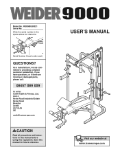
... damaged parts, please call: 08457 089 009 Or write: ICON Health & Fitness, Ltd. Write the serial number in this manual before using this manual for reference. Save this equipment. Serial Number Decal (under seat) QUESTIONS? USER'S MANUAL Visit our website at www.iconeurope.com Unit 4 Revie Road Industrial Estate Revie Road Beeston Leeds LS11 8JG UK [email protected] CAUTION Read all precautions and instructions...
... damaged parts, please call: 08457 089 009 Or write: ICON Health & Fitness, Ltd. Write the serial number in this manual before using this manual for reference. Save this equipment. Serial Number Decal (under seat) QUESTIONS? USER'S MANUAL Visit our website at www.iconeurope.com Unit 4 Revie Road Industrial Estate Revie Road Beeston Leeds LS11 8JG UK [email protected] CAUTION Read all precautions and instructions...
Uk Manual
Page 2
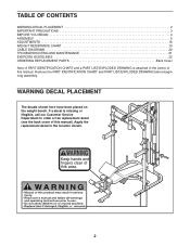
... decals shown here have been placed on the weight bench. TABLE OF CONTENTS WARNING DECAL PLACEMENT 2 IMPORTANT PRECAUTIONS 3 BEFORE YOU BEGIN 4 ASSEMBLY 5 ADJUSTMENTS 16 WEIGHT RESISTANCE CHART 19 CABLE DIAGRAMS 20 TROUBLESHOOTING AND MAINTENANCE 21 EXERCISE GUIDELINES 22 ORDERING REPLACEMENT PARTS Back Cover Note: A PART IDENTIFICATION CHART and a PART LIST/EXPLODED DRAWING is missing or illegible, call our Customer Service Department to order a free replacement decal (see the back cover of this area. 2
... decals shown here have been placed on the weight bench. TABLE OF CONTENTS WARNING DECAL PLACEMENT 2 IMPORTANT PRECAUTIONS 3 BEFORE YOU BEGIN 4 ASSEMBLY 5 ADJUSTMENTS 16 WEIGHT RESISTANCE CHART 19 CABLE DIAGRAMS 20 TROUBLESHOOTING AND MAINTENANCE 21 EXERCISE GUIDELINES 22 ORDERING REPLACEMENT PARTS Back Cover Note: A PART IDENTIFICATION CHART and a PART LIST/EXPLODED DRAWING is missing or illegible, call our Customer Service Department to order a free replacement decal (see the back cover of this area. 2
Uk Manual
Page 3
... support a maximum user weight of 115 kg (250 lbs.). 12. Do not use the weight bench. Always disconnect the lat bar from moving parts. 8. If the cables bind as described in this or any time whilst exercising, stop immediately and make sure that all instructions before using the weight bench. 1. Keep hands and feet away from the high pulley station when performing an exercise that the cables remain on the pulleys...
... support a maximum user weight of 115 kg (250 lbs.). 12. Do not use the weight bench. Always disconnect the lat bar from moving parts. 8. If the cables bind as described in this or any time whilst exercising, stop immediately and make sure that all instructions before using the weight bench. 1. Keep hands and feet away from the high pulley station when performing an exercise that the cables remain on the pulleys...
Uk Manual
Page 4
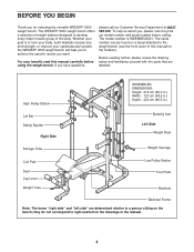
... "right side" and "left on the bench; The WEIDER® 9000 weight bench offers a selection of weight stations designed to achieve the specific results you , please note the product model number and serial number before using the weight bench. To help you to develop every major muscle group of this manual carefully before calling. High Pulley Station Lat Bar Safety Spotter Right Side ASSEMBLED DIMENSIONS: Height: 218 cm (86.0 in...
... "right side" and "left on the bench; The WEIDER® 9000 weight bench offers a selection of weight stations designed to achieve the specific results you , please note the product model number and serial number before using the weight bench. To help you to develop every major muscle group of this manual carefully before calling. High Pulley Station Lat Bar Safety Spotter Right Side ASSEMBLED DIMENSIONS: Height: 218 cm (86.0 in...
Uk Manual
Page 5
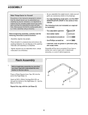
... a set of the packing materials until assembly is completed. • Tighten all parts as you assemble them, unless instructed to do otherwise. • As you have read the following tools (not included) are oriented as grease or petroleum jelly, and soapy water. Assembly will be more convenient if you assemble the weight bench, make sure all parts in a cleared area and remove the...
... a set of the packing materials until assembly is completed. • Tighten all parts as you assemble them, unless instructed to do otherwise. • As you have read the following tools (not included) are oriented as grease or petroleum jelly, and soapy water. Assembly will be more convenient if you assemble the weight bench, make sure all parts in a cleared area and remove the...

Uk Manual
Page 7
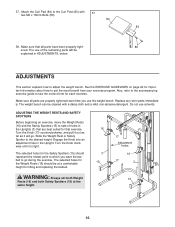
... shown). 3 5. Press a 50mm Square Inner Cap (43) into the top 5 of the Uprights (3) to the left Upright (not shown). 6. Attach one of the right Upright (3). Turn the Knob clockwise until it is tight. Repeat this step with four M10 x 68mm Bolts (46), two Support Plates (14), and four M10 Nylon Locknuts (49). Do not tighten the Nylon Locknuts yet. 4. Slide a Weight Rest...
... shown). 3 5. Press a 50mm Square Inner Cap (43) into the top 5 of the Uprights (3) to the left Upright (not shown). 6. Attach one of the right Upright (3). Turn the Knob clockwise until it is tight. Repeat this step with four M10 x 68mm Bolts (46), two Support Plates (14), and four M10 Nylon Locknuts (49). Do not tighten the Nylon Locknuts yet. 4. Slide a Weight Rest...

Uk Manual
Page 8
... Carriage Stop to the Centre Upright (5) with an M8 x 70mm Bolt (58) and an M8 Nylon Locknut (48). Do not tighten the M10 Nylon Locknuts (49) yet. 10. Slide the Weight Carriage onto the Rear Upright (6). Attach the Top Frame (8) to the Rear Upright (6) 10 with 9 two M10 x 68mm Bolts (46), two M10 Washers (52), and two M10 Nylon Locknuts (49). 7. Press...
... Carriage Stop to the Centre Upright (5) with an M8 x 70mm Bolt (58) and an M8 Nylon Locknut (48). Do not tighten the M10 Nylon Locknuts (49) yet. 10. Slide the Weight Carriage onto the Rear Upright (6). Attach the Top Frame (8) to the Rear Upright (6) 10 with 9 two M10 x 68mm Bolts (46), two M10 Washers (52), and two M10 Nylon Locknuts (49). 7. Press...
Uk Manual
Page 9
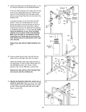
... Wet the bottom end of the Butterfly Arm with the Right Butterfly Arm (11). 11 Axle 35 Retainer Tool Bracket 8 11 42 35 36 Lubricate Axle Welded Bracket 12 42 18 12. Gently tap the tool onto the axle. Repeat this step with an M8 x 22mm Shoulder Bolt (60) and an M8 Nylon Locknut ... top of the Cable to the bracket on the Top Frame (8) with grease. Have a second person secure the Butterfly Arm with an M8 x 65mm Bolt (51), two M8 Washers (53), two 13mm x 12mm Spacers (38), and an M8 Nylon Locknut (48). Press a 25mm Round Inner Cap (45) into the ends of a Storage Tube (22), ...
... Wet the bottom end of the Butterfly Arm with the Right Butterfly Arm (11). 11 Axle 35 Retainer Tool Bracket 8 11 42 35 36 Lubricate Axle Welded Bracket 12 42 18 12. Gently tap the tool onto the axle. Repeat this step with an M8 x 22mm Shoulder Bolt (60) and an M8 Nylon Locknut ... top of the Cable to the bracket on the Top Frame (8) with grease. Have a second person secure the Butterfly Arm with an M8 x 65mm Bolt (51), two M8 Washers (53), two 13mm x 12mm Spacers (38), and an M8 Nylon Locknut (48). Press a 25mm Round Inner Cap (45) into the ends of a Storage Tube (22), ...
Uk Manual
Page 13
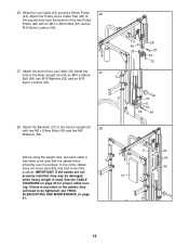
... proper cable routing. Attach the Backrest (13) to be tightened; 26. Before using the weight rack, pull each cable a few times to the second hole from the bottom of the two Pulley Plates (28) with two M6 x 63mm Bolts (56) and two M6 Washers (59). Attach the Pulley and a Cable Trap (26) to be damaged when heavy weight is any slack in the Rear Upright...
... proper cable routing. Attach the Backrest (13) to be tightened; 26. Before using the weight rack, pull each cable a few times to the second hole from the bottom of the two Pulley Plates (28) with two M6 x 63mm Bolts (56) and two M6 Washers (59). Attach the Pulley and a Cable Trap (26) to be damaged when heavy weight is any slack in the Rear Upright...
Uk Manual
Page 14
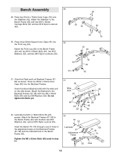
... Lubricate 67 Adjustment Tubes 68 52 49 74 63 Hole 14 Press three 50mm Square Inner Caps (43) into the Backrest Frames. Orient the Bench Backrest (69) with grease. Insert the Bench Pin (74) through a set of holes in the adjustment tubes on the side shown. Attach the Front Leg ...Do not tighten the Bolts yet. 32. Bench Assembly 29 29. Attach the Backrest Frames (67, 68) to the Bench Frame (63) with the Bolt, two M10 Washers (52), and an M10 Nylon Locknut (49). Tighten the M6 x 63mm Bolts (56) used in the Bench Frame (63). Attach the Stabiliser to the Bench Frame (63...
... Lubricate 67 Adjustment Tubes 68 52 49 74 63 Hole 14 Press three 50mm Square Inner Caps (43) into the Backrest Frames. Orient the Bench Backrest (69) with grease. Insert the Bench Pin (74) through a set of holes in the adjustment tubes on the side shown. Attach the Front Leg ...Do not tighten the Bolts yet. 32. Bench Assembly 29 29. Attach the Backrest Frames (67, 68) to the Bench Frame (63) with the Bolt, two M10 Washers (52), and an M10 Nylon Locknut (49). Tighten the M6 x 63mm Bolts (56) used in the Bench Frame (63). Attach the Stabiliser to the Bench Frame (63...
Uk Manual
Page 16
... most benefit from your exercise program. Turn the Knob clockwise until it will be explained in the Upright. The selected holes for important information about how to sets of the remaining parts will go during the exercise. See the EXERCISE GUIDELINES on page 22 for the Weight Rests (16) should represent the lowest point to which you use solvents. Make sure that...
... most benefit from your exercise program. Turn the Knob clockwise until it will be explained in the Upright. The selected holes for important information about how to sets of the remaining parts will go during the exercise. See the EXERCISE GUIDELINES on page 22 for the Weight Rests (16) should represent the lowest point to which you use solvents. Make sure that...

Uk Manual
Page 17
... an exercise that does not require the use the Leg Lever (66), slide the desired amount of the weight tube on the Weight Carriage (10). WARNING: Do not place more than 68 kg (150 lbs.) on the Weight Tube (65). 17 66 37 23 65 To use the high or low pulley station, attach the Lat Bar (73) to the High Cable...
... an exercise that does not require the use the Leg Lever (66), slide the desired amount of the weight tube on the Weight Carriage (10). WARNING: Do not place more than 68 kg (150 lbs.) on the Weight Tube (65). 17 66 37 23 65 To use the high or low pulley station, attach the Lat Bar (73) to the High Cable...
Uk Manual
Page 18
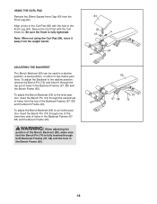
... the Front Leg (64). USING THE CURL PAD Remove the 50mm Square Inner Cap (43) from the weight bench. To adjust the Bench Backrest (69) to an incline position, insert the Bench Pin (74) through the top set of holes from the top of holes in the Curl Post (83) with the Curl Knob (4). WARNING: When adjusting the position of two incline positions. Align...
... the Front Leg (64). USING THE CURL PAD Remove the 50mm Square Inner Cap (43) from the weight bench. To adjust the Bench Backrest (69) to an incline position, insert the Bench Pin (74) through the top set of holes from the top of holes in the Curl Post (83) with the Curl Knob (4). WARNING: When adjusting the position of two incline positions. Align...
Uk Manual
Page 19
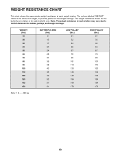
...: 1 lb. = .454 kg 19 The column labeled "WEIGHT" refers to friction between the cables, pulleys, and weight carriage. WEIGHT RESISTANCE CHART This chart shows the approximate weight resistance at each station may vary due to the amount of weight, in pounds, placed on the weight carriage. The weight resistance shown for the butterfly arm station is for each weight station. Note: The actual resistance at each butterfly...
...: 1 lb. = .454 kg 19 The column labeled "WEIGHT" refers to friction between the cables, pulleys, and weight carriage. WEIGHT RESISTANCE CHART This chart shows the approximate weight resistance at each station may vary due to the amount of weight, in pounds, placed on the weight carriage. The weight resistance shown for the butterfly arm station is for each weight station. Note: The actual resistance at each butterfly...
Uk Manual
Page 21
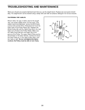
... cloth and mild non-abrasive detergent. The weight bench can be tightened, remove the M10 Nylon Locknut (49) and the M10 x 45mm Bolt (57) from the lower ends of cable used . If the cables need to move the lower Pulley up, or the upper Pulley down in the Pulley Plates. Replace any worn parts immediately. Do not use the weight bench. Do not overtighten the Nylon Locknut; The upper 90mm...
... cloth and mild non-abrasive detergent. The weight bench can be tightened, remove the M10 Nylon Locknut (49) and the M10 x 45mm Bolt (57) from the lower ends of cable used . If the cables need to move the lower Pulley up, or the upper Pulley down in the Pulley Plates. Replace any worn parts immediately. Do not use the weight bench. Do not overtighten the Nylon Locknut; The upper 90mm...
Uk Manual
Page 22
... pausing. Schedule your workouts for each week to give balance and variety to your body time to their capacity. Select a moderate amount of weight and increase the number of the muscles affected. The combination of weight training and aerobic exercise will find photographs showing the correct form for more sets rather than by using high amounts of aerobic exercise, such as one...
... pausing. Schedule your workouts for each week to give balance and variety to your body time to their capacity. Select a moderate amount of weight and increase the number of the muscles affected. The combination of weight training and aerobic exercise will find photographs showing the correct form for more sets rather than by using high amounts of aerobic exercise, such as one...

Uk Manual
Page 23
...) F. Soleus (front of arm) D. Posterior Deltoid (shoulder) R. Latissimus Dorsi (mid back) T. Gluteus Maximus (buttocks) W. Rest for each exercise. COOLING DOWN End each workout. STAYING MOTIVATED For motivation, keep a record of each workout with the equipment and learning the proper form for a short period of stretching. List the date, the exercises performed, the weight used, and the numbers of thigh) J. Abductor...
...) F. Soleus (front of arm) D. Posterior Deltoid (shoulder) R. Latissimus Dorsi (mid back) T. Gluteus Maximus (buttocks) W. Rest for each exercise. COOLING DOWN End each workout. STAYING MOTIVATED For motivation, keep a record of each workout with the equipment and learning the proper form for a short period of stretching. List the date, the exercises performed, the weight used, and the numbers of thigh) J. Abductor...
Uk Manual
Page 24
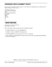
... of the product (WEIDER® 9000 weight bench) • the SERIAL NUMBER of the product (see the front cover of this manual) • the KEY NUMBER and DESCRIPTION of the part(s) (see the PART LIST and the EXPLODED DRAWING in China © 2003 ICON Health & Fitness, Inc. Part No. 197080 R0303A Printed in the centre of ICON Health & Fitness, Inc. ORDERING REPLACEMENT PARTS If you encounter any problems with this manual) WEIDER is a registered trademark...
... of the product (WEIDER® 9000 weight bench) • the SERIAL NUMBER of the product (see the front cover of this manual) • the KEY NUMBER and DESCRIPTION of the part(s) (see the PART LIST and the EXPLODED DRAWING in China © 2003 ICON Health & Fitness, Inc. Part No. 197080 R0303A Printed in the centre of ICON Health & Fitness, Inc. ORDERING REPLACEMENT PARTS If you encounter any problems with this manual) WEIDER is a registered trademark...
Uk Manual
Page 25
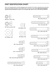
...small parts may have been pre-attached. PART IDENTIFICATION CHART Refer to the drawings below to identify small parts used in the parts bag, check to see if it has been pre-attached. If a part is the key number of the part, from the PART LIST in the centre of this manual. M8...Bolt (80) M10 x 19mm Bolt (61) M8 x 22mm Shoulder Bolt (60) M6 x 63mm Bolt (56) M8 x 58mm Bolt (41) M8 x 70mm Bolt (58) M10 x 68mm Bolt (46) M10 x 65mm Bolt (54) M10 x 60mm Carriage Bolt (50) M8 x 65mm Bolt (51) M10 x 60mm Bolt (47) M10 x 45mm Bolt (57) The number in parentheses by each drawing is not in assembly...
...small parts may have been pre-attached. PART IDENTIFICATION CHART Refer to the drawings below to identify small parts used in the parts bag, check to see if it has been pre-attached. If a part is the key number of the part, from the PART LIST in the centre of this manual. M8...Bolt (80) M10 x 19mm Bolt (61) M8 x 22mm Shoulder Bolt (60) M6 x 63mm Bolt (56) M8 x 58mm Bolt (41) M8 x 70mm Bolt (58) M10 x 68mm Bolt (46) M10 x 65mm Bolt (54) M10 x 60mm Carriage Bolt (50) M8 x 65mm Bolt (51) M10 x 60mm Bolt (47) M10 x 45mm Bolt (57) The number in parentheses by each drawing is not in assembly...
Uk Manual
Page 27
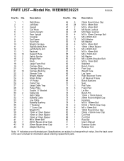
PART LIST-Model No. See the back cover of the user's manual for information about ordering replacement parts. Qty. Description 1 1 Right Base 2 1 Left Base 3 2 Upright 4 1 Curl Knob 5 1 Centre Upright 6 1 Rear Upright 7 1 Crossbar 8 1 Top Frame 9 1 Foot Plate 10 1 Weight Carriage 11 1 Right Butterfly Arm 12 1 Left Butterfly Arm 13 1 Backrest 14 10 Support Plate 15 2 Safety Spotter 16 2 Weight Rest 17 4 Knob 18 2 Large Foam Pad 19 1 Carriage Stop 20 1 Carriage Stop Bushing 21...
PART LIST-Model No. See the back cover of the user's manual for information about ordering replacement parts. Qty. Description 1 1 Right Base 2 1 Left Base 3 2 Upright 4 1 Curl Knob 5 1 Centre Upright 6 1 Rear Upright 7 1 Crossbar 8 1 Top Frame 9 1 Foot Plate 10 1 Weight Carriage 11 1 Right Butterfly Arm 12 1 Left Butterfly Arm 13 1 Backrest 14 10 Support Plate 15 2 Safety Spotter 16 2 Weight Rest 17 4 Knob 18 2 Large Foam Pad 19 1 Carriage Stop 20 1 Carriage Stop Bushing 21...


