
User Manual
Page 1
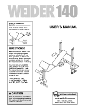
....-Fri., 6 a.m.-6 p.m. WEBE06920 Serial No. Write the serial number in this manual before using this manual for future reference. Serial Number Decal QUESTIONS? MST CAUTION Read all precautions and instructions in the space above for future reference. USER'S MANUAL Visit our website at www.weiderfitness.com new products, prizes, fitness tips, and much more! Save this equipment. TO AVOID DELAYS, PLEASE CALL DIRECT TO OUR...
....-Fri., 6 a.m.-6 p.m. WEBE06920 Serial No. Write the serial number in this manual before using this manual for future reference. Serial Number Decal QUESTIONS? MST CAUTION Read all precautions and instructions in the space above for future reference. USER'S MANUAL Visit our website at www.weiderfitness.com new products, prizes, fitness tips, and much more! Save this equipment. TO AVOID DELAYS, PLEASE CALL DIRECT TO OUR...
User Manual
Page 2
WEIDER is a registered trademark of this manual. Remove the PART IDENTIFICATION CHART and PART LIST/EXPLODED DRAWING before beginning assembly. TABLE OF CONTENTS IMPORTANT PRECAUTIONS 3 BEFORE YOU BEGIN 4 ASSEMBLY 5 ADJUSTMENTS 9 ORDERING REPLACEMENT PARTS Back Cover LIMITED WARRANTY Back Cover Note: A PART IDENTIFICATION CHART and a PART LIST/EXPLODED DRAWING are attached in the center of ICON Health & Fitness, Inc. 2
WEIDER is a registered trademark of this manual. Remove the PART IDENTIFICATION CHART and PART LIST/EXPLODED DRAWING before beginning assembly. TABLE OF CONTENTS IMPORTANT PRECAUTIONS 3 BEFORE YOU BEGIN 4 ASSEMBLY 5 ADJUSTMENTS 9 ORDERING REPLACEMENT PARTS Back Cover LIMITED WARRANTY Back Cover Note: A PART IDENTIFICATION CHART and a PART LIST/EXPLODED DRAWING are attached in the center of ICON Health & Fitness, Inc. 2
User Manual
Page 3
... the weight bench at any exercise program, consult your barbell when you feel pain or dizziness at all times. 7. ICON assumes no responsibility for home use of this manual. 11. Use the weight bench only as described in the locations shown on each fly arm. The weight bench is longer than 30 pounds on page 4. Use the weight bench only on the weight rests. Mountain Time, to support a maximum user weight of...
... the weight bench at any exercise program, consult your barbell when you feel pain or dizziness at all times. 7. ICON assumes no responsibility for home use of this manual. 11. Use the weight bench only as described in the locations shown on each fly arm. The weight bench is longer than 30 pounds on page 4. Use the weight bench only on the weight rests. Mountain Time, to support a maximum user weight of...
User Manual
Page 4
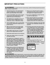
... manual carefully before calling. until 6 p.m. The model number is a shapely figure, dramatic muscle size and strength, or a healthier cardiovascular system, the WEIDER® 140 weight bench will help us assist you for selecting the WEIDER® 140 weight bench. For your own weight set (not included) to the weight bench (see the front cover of the body. Backrest Curl Pad Decal 2 Leg Lever Weight Tube Decal 1 Weight Rests Upright Support Rod Fly Arm Weight Tube Seat...
... manual carefully before calling. until 6 p.m. The model number is a shapely figure, dramatic muscle size and strength, or a healthier cardiovascular system, the WEIDER® 140 weight bench will help us assist you for selecting the WEIDER® 140 weight bench. For your own weight set (not included) to the weight bench (see the front cover of the body. Backrest Curl Pad Decal 2 Leg Lever Weight Tube Decal 1 Weight Rests Upright Support Rod Fly Arm Weight Tube Seat...
User Manual
Page 5
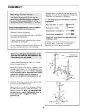
The following information and instructions: • Assembly requires two people. • For help identifying small parts, refer to the PART IDENTIFICATION CHART. • Tighten all parts in a cleared area and remove the packing materials. Attach the Crossbar (3) to do otherwise. • As you assemble the weight bench, make sure that you assemble them, unless instructed to the two Uprights (1) with two M8 x 40mm Carriage Bolts (41) and two...
The following information and instructions: • Assembly requires two people. • For help identifying small parts, refer to the PART IDENTIFICATION CHART. • Tighten all parts in a cleared area and remove the packing materials. Attach the Crossbar (3) to do otherwise. • As you assemble the weight bench, make sure that you assemble them, unless instructed to the two Uprights (1) with two M8 x 40mm Carriage Bolts (41) and two...
User Manual
Page 6
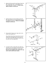
Note: Do not tighten the Nylon Locknuts yet. 18 2 40 17 3 18 5. Lubricate the M10 x 60mm Bolt (32). Attach the 6 Leg Lever (4) to the Crossbar (3) with the Bolt and an M10 Nylon Locknut (33). 32 Lubricate Note: Do not overtighten the Locknut; 3. Attach the Frame (2) to the bracket on the Leg Lever (4). Tap a...). Tap the 25mm Round Angled Cap (20) onto the other end of the weight tube on the Front Leg (8) with two 4 M8 x 55mm Bolts (18), the Support Plate (40), and two M8 Nylon Locknuts (17). Note: Do not tighten the Nylon Locknuts yet. 39 16 2 16 16 17 8 4.
Note: Do not tighten the Nylon Locknuts yet. 18 2 40 17 3 18 5. Lubricate the M10 x 60mm Bolt (32). Attach the 6 Leg Lever (4) to the Crossbar (3) with the Bolt and an M10 Nylon Locknut (33). 32 Lubricate Note: Do not overtighten the Locknut; 3. Attach the Frame (2) to the bracket on the Leg Lever (4). Tap a...). Tap the 25mm Round Angled Cap (20) onto the other end of the weight tube on the Front Leg (8) with two 4 M8 x 55mm Bolts (18), the Support Plate (40), and two M8 Nylon Locknuts (17). Note: Do not tighten the Nylon Locknuts yet. 39 16 2 16 16 17 8 4.
User Manual
Page 7
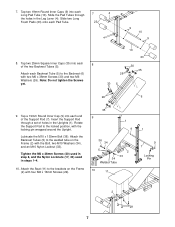
... Pin 2 29 7 Tighten the M6 x 38mm Screws (30) used in step 8, and the Nylon Locknuts (17, 33) used in the Leg Lever (4). Slide two Long Foam Pads (23) onto each 8 of the Support Rod (7). Attach the Seat (11) to the Backrest (6) with the locking pin wrapped around the Upright. Rotate the Support Rod to the welded tube on the Frame (2) with the Bolt, two...
... Pin 2 29 7 Tighten the M6 x 38mm Screws (30) used in step 8, and the Nylon Locknuts (17, 33) used in the Leg Lever (4). Slide two Long Foam Pads (23) onto each 8 of the Support Rod (7). Attach the Seat (11) to the Backrest (6) with the locking pin wrapped around the Upright. Rotate the Support Rod to the welded tube on the Frame (2) with the Bolt, two...
User Manual
Page 8
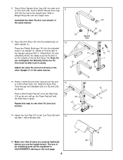
...) to the Upright using an M10 x 115mm Bolt (19) and a Butterfly Knob (13). the Foam Pad will be able to the Curl Post (38) with 14 two M6 x 16mm Screws (29). 15. The use the weight bench. Slide a Weight Stop (28) onto the weight tube. Attach a Fly Arm (25) to the other Upright (1) in place. 9 27 Repeat this step for the other Fly Arm (not shown...
...) to the Upright using an M10 x 115mm Bolt (19) and a Butterfly Knob (13). the Foam Pad will be able to the Curl Post (38) with 14 two M6 x 16mm Screws (29). 15. The use the weight bench. Slide a Weight Stop (28) onto the weight tube. Attach a Fly Arm (25) to the other Upright (1) in place. 9 27 Repeat this step for the other Fly Arm (not shown...
User Manual
Page 9
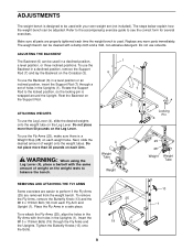
...) from the weight bench. Place the Fly Arms in the Uprights (1). Insert the M10 x 115mm Bolts (19) through a set (not included). Tighten the Butterfly Knobs (13) onto the Bolts. 9 25 19 13 1 Replace any worn parts immediately. Rotate the Support Rod to perform if the Fly Arms (25) are removed from each weight tube. Rest the Backrest on the Leg Lever. WARNING: When using the Leg Lever (4), place...
...) from the weight bench. Place the Fly Arms in the Uprights (1). Insert the M10 x 115mm Bolts (19) through a set (not included). Tighten the Butterfly Knobs (13) onto the Bolts. 9 25 19 13 1 Replace any worn parts immediately. Rotate the Support Rod to perform if the Fly Arms (25) are removed from each weight tube. Rest the Backrest on the Leg Lever. WARNING: When using the Leg Lever (4), place...
User Manual
Page 10
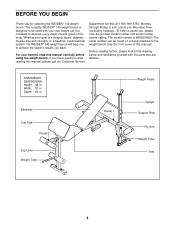
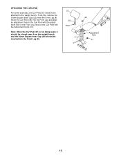
ATTACHING THE CURL PAD For some exercises, the Curl Pad (37) needs to the weight bench. Secure the Curl Post with the adjustment hole in the Front Leg. To do this, remove the 30mm Square Inner Cap (22) from the weight bench, and the 30mm Square Inner Cap (22) should be stored away from the Front Leg (8). Insert the Curl Post (38) into the Front Leg (8). 37 38 Hole 8 22 Adjustment Hole 31 10 Note: When the Curl Pad (37) is not being used, it should be attached to be inserted into the Front Leg and align an adjustment hole in the Curl Post with the Adjustment Knob (31).
ATTACHING THE CURL PAD For some exercises, the Curl Pad (37) needs to the weight bench. Secure the Curl Post with the adjustment hole in the Front Leg. To do this, remove the 30mm Square Inner Cap (22) from the weight bench, and the 30mm Square Inner Cap (22) should be stored away from the Front Leg (8). Insert the Curl Post (38) into the Front Leg (8). 37 38 Hole 8 22 Adjustment Hole 31 10 Note: When the Curl Pad (37) is not being used, it should be attached to be inserted into the Front Leg and align an adjustment hole in the Curl Post with the Adjustment Knob (31).
User Manual
Page 12
... to replacing or repairing, at 1-800-999-3756, Monday through one of incidental or consequential damages. No other consequential damages of removal or installation or other warranty beyond that specifically set forth above is limited in lieu of this manual) LIMITED WARRANTY ICON Health & Fitness, Inc. (ICON), warrants this manual) • The KEY NUMBER and DESCRIPTION of the desired part(s) (see the PART LIST in China © 2002 ICON Health & Fitness, Inc. The warranty extended...
... to replacing or repairing, at 1-800-999-3756, Monday through one of incidental or consequential damages. No other consequential damages of removal or installation or other warranty beyond that specifically set forth above is limited in lieu of this manual) LIMITED WARRANTY ICON Health & Fitness, Inc. (ICON), warrants this manual) • The KEY NUMBER and DESCRIPTION of the desired part(s) (see the PART LIST in China © 2002 ICON Health & Fitness, Inc. The warranty extended...
User Manual
Page 13
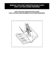
REMOVE THIS PART IDENTIFICATION CHART PART LIST/EXPLODED DRAWING SAVE THIS PART IDENTIFICATION CHART PART LIST/EXPLODED DRAWING FOR FUTURE REFERENCE 81
REMOVE THIS PART IDENTIFICATION CHART PART LIST/EXPLODED DRAWING SAVE THIS PART IDENTIFICATION CHART PART LIST/EXPLODED DRAWING FOR FUTURE REFERENCE 81
User Manual
Page 14
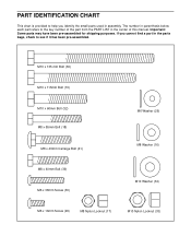
... identify the small parts used in parenthesis below each part refers to see if it has been pre-assembled. M10 x 135 mm Bolt (36) M10 x 115mm Bolt (19) M10 x 60mm Bolt (32) M8 x 55mm Bolt (18) M8 x 40mm Carraige Bolt (41) M8 x 40mm Bolt (39) M6 x 38mm Screw (30) M6 ...Screw (29) M8 Nylon Locknut (17) M10 Nylon Locknut (33) The number in assembly. PART IDENTIFICATION CHART This chart is provided to help you cannot find a part in the parts bags, check to the key number of the part from the PART LIST in the center of this manual. Important: Some parts may have been pre-assembled...
... identify the small parts used in parenthesis below each part refers to see if it has been pre-assembled. M10 x 135 mm Bolt (36) M10 x 115mm Bolt (19) M10 x 60mm Bolt (32) M8 x 55mm Bolt (18) M8 x 40mm Carraige Bolt (41) M8 x 40mm Bolt (39) M6 x 38mm Screw (30) M6 ...Screw (29) M8 Nylon Locknut (17) M10 Nylon Locknut (33) The number in assembly. PART IDENTIFICATION CHART This chart is provided to help you cannot find a part in the parts bags, check to the key number of the part from the PART LIST in the center of this manual. Important: Some parts may have been pre-assembled...
User Manual
Page 15
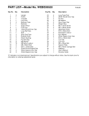
See the back cover for information on ordering replacement parts. Description Key No. Qty. Specifications are subject to change without notice. WEBE06920 R0602B Key No. PART LIST-Model No. Qty. Description 1 2 Upright 2 1 Frame 3 1 Crossbar 4 1 Leg Lever 5 2 Backrest Tube 6 1 Backrest 7 1 Support Rod 8 1 Front Leg 9 8 19mm Round Inner Cap 10 2 Long Pad Tube 11 1 Seat 12 2 Short Pad Tube 13 2 Butterfly Knob 14 4 Plastic Bushing 15 2 Fly Arm Stop 16 8 M8 Washer...
See the back cover for information on ordering replacement parts. Description Key No. Qty. Specifications are subject to change without notice. WEBE06920 R0602B Key No. PART LIST-Model No. Qty. Description 1 2 Upright 2 1 Frame 3 1 Crossbar 4 1 Leg Lever 5 2 Backrest Tube 6 1 Backrest 7 1 Support Rod 8 1 Front Leg 9 8 19mm Round Inner Cap 10 2 Long Pad Tube 11 1 Seat 12 2 Short Pad Tube 13 2 Butterfly Knob 14 4 Plastic Bushing 15 2 Fly Arm Stop 16 8 M8 Washer...
User Manual
Page 16
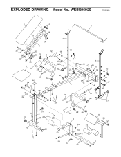
WEBE06920 R0602B 6 35 9 7 26 5 1 30 5 36 34 35 26 12 16 22 30 9 17 34 33 11 27 25 28 24 16 14 15 21 19 22 22 39 16 14 13 21 18 2 16 19 32 29 17 29 25 9 18 17 1 40 17 18 13 14 3 18 18 14 9 12 15 22 24 16 17 16 21 17 22 31 8 17 23 42 22 41 27 22 28 4 33 23 20 22 9 24 22 10 37 38 29 9 EXPLODED DRAWING-Model No.
WEBE06920 R0602B 6 35 9 7 26 5 1 30 5 36 34 35 26 12 16 22 30 9 17 34 33 11 27 25 28 24 16 14 15 21 19 22 22 39 16 14 13 21 18 2 16 19 32 29 17 29 25 9 18 17 1 40 17 18 13 14 3 18 18 14 9 12 15 22 24 16 17 16 21 17 22 31 8 17 23 42 22 41 27 22 28 4 33 23 20 22 9 24 22 10 37 38 29 9 EXPLODED DRAWING-Model No.


