
User Manual
Page 8
...representatives of energy emitted by Wireless LAN devices however is far much less than 20 cm. In normal operating configuration, the LCD in the user Refer to Radio Frequency Radiation The radiated output power of scientists who continually review and interpret the extensive research...literature. These standards and recommendations reflect the consensus of the scientific community and result from deliberations of panels and committees of the TOSHIBA Wireless LAN Mini PCI Card is safe for additional information. Exposure to the Regulatory Statements as harmful. In some situations or...
...representatives of energy emitted by Wireless LAN devices however is far much less than 20 cm. In normal operating configuration, the LCD in the user Refer to Radio Frequency Radiation The radiated output power of scientists who continually review and interpret the extensive research...literature. These standards and recommendations reflect the consensus of the scientific community and result from deliberations of panels and committees of the TOSHIBA Wireless LAN Mini PCI Card is safe for additional information. Exposure to the Regulatory Statements as harmful. In some situations or...
User Manual
Page 78
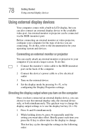
This hot key cycles through the settings in LCD display, but you can easily attach an external monitor or projector to your computer for the type of the computer. 2 Connect the device's power cable ...
This hot key cycles through the settings in LCD display, but you can easily attach an external monitor or projector to your computer for the type of the computer. 2 Connect the device's power cable ...
User Manual
Page 183
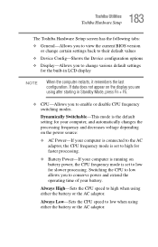
... allows you to conserve power and extend the operating time of your computer is running on the display you are using after starting in LCD display NOTE When the computer restarts, it remembers the last configuration. Always High-Sets the CPU speed to high when using either the ... Power-If your battery. Always Low-Sets the CPU speed to low when using either the battery or the AC adaptor. 183 Toshiba Utilities Toshiba Hardware Setup The Toshiba Hardware Setup screen has the following tabs: ❖ General-Allows you to view the current BIOS version or change certain settings back...
... allows you to conserve power and extend the operating time of your computer is running on the display you are using after starting in LCD display NOTE When the computer restarts, it remembers the last configuration. Always High-Sets the CPU speed to high when using either the ... Power-If your battery. Always Low-Sets the CPU speed to low when using either the battery or the AC adaptor. 183 Toshiba Utilities Toshiba Hardware Setup The Toshiba Hardware Setup screen has the following tabs: ❖ General-Allows you to view the current BIOS version or change certain settings back...

User Manual
Page 286
... Hypertext Markup Language IEEE Institute of Electrical and Electronics Engineers I/O input/output IRQ interrupt request ISP Internet service provider KB kilobyte LAN local area network LCD liquid crystal display LPT1 line printer port 1 (parallel port) LSI large-scale integration MB megabyte MIDI Musical Instrument Digital Interface PC personal computer PCI Peripheral...
... Hypertext Markup Language IEEE Institute of Electrical and Electronics Engineers I/O input/output IRQ interrupt request ISP Internet service provider KB kilobyte LAN local area network LCD liquid crystal display LPT1 line printer port 1 (parallel port) LSI large-scale integration MB megabyte MIDI Musical Instrument Digital Interface PC personal computer PCI Peripheral...

User Manual
Page 287
... some processing) may appear in its simplest form there is one that provides a compatible connection between two units. Compare direct current (DC). A liquid crystal display (LCD) made from wider angles than most passive-matrix displays. An adapter can take a number of liquid crystal cells using active-matrix technology. AC reverses its...
... some processing) may appear in its simplest form there is one that provides a compatible connection between two units. Compare direct current (DC). A liquid crystal display (LCD) made from wider angles than most passive-matrix displays. An adapter can take a number of liquid crystal cells using active-matrix technology. AC reverses its...
User Manual
Page 294
... any other on the network. load - A system's logical drives may be partitioned into memory for processing. LAN (local area network) - See LAN. liquid crystal display (LCD) - A section of display that provides electronic mail, the World Wide Web, and other devices dispersed over the electrodes permits only non-polarized light to pass...
... any other on the network. load - A system's logical drives may be partitioned into memory for processing. LAN (local area network) - See LAN. liquid crystal display (LCD) - A section of display that provides electronic mail, the World Wide Web, and other devices dispersed over the electrodes permits only non-polarized light to pass...
Maintenance Manual
Page 4
...the removal and replacement of the FRUs. Appendices The appendices describe the following parts: Chapter 1 Hardware Overview describes the TECRA A8 series / Satellite Pro A120 series system unit and each FRU. Chapter 2 Troubleshooting Procedures explains how to diagnose and resolve... : ‰ Handling the LCD module ‰ Board layout ‰ Pin assignments ‰ Keyboard scan/character codes ‰ Key layout ‰ Wiring diagrams ‰ BIOS rewrite procedures ‰ EC/KBC rewrite procedures ‰ Reliability iv [CONFIDENTIAL] TECRA A8 /Satellite Pro A120 Maintenance Manual...
...the removal and replacement of the FRUs. Appendices The appendices describe the following parts: Chapter 1 Hardware Overview describes the TECRA A8 series / Satellite Pro A120 series system unit and each FRU. Chapter 2 Troubleshooting Procedures explains how to diagnose and resolve... : ‰ Handling the LCD module ‰ Board layout ‰ Pin assignments ‰ Keyboard scan/character codes ‰ Key layout ‰ Wiring diagrams ‰ BIOS rewrite procedures ‰ EC/KBC rewrite procedures ‰ Reliability iv [CONFIDENTIAL] TECRA A8 /Satellite Pro A120 Maintenance Manual...
Maintenance Manual
Page 8
... 4.23 Heat sink/CPU ...4-52 4.24 PC card slot ...4-56 4.25 LCD unit/FL inverter 4-57 4.26 Cover latch ...4-62 4.27 Display rear cover ...4-63 4.28 Wireless LAN antenna/Bluetooth antenna 4-65 4.29 Hinge...4-71 4.30 Speaker...4-73 4.31 Fluorescent Lamp...4-77 viii [CONFIDENTIAL] TECRA A8 /Satellite Pro A120 Maintenance Manual (960-573)
... 4.23 Heat sink/CPU ...4-52 4.24 PC card slot ...4-56 4.25 LCD unit/FL inverter 4-57 4.26 Cover latch ...4-62 4.27 Display rear cover ...4-63 4.28 Wireless LAN antenna/Bluetooth antenna 4-65 4.29 Hinge...4-71 4.30 Speaker...4-73 4.31 Fluorescent Lamp...4-77 viii [CONFIDENTIAL] TECRA A8 /Satellite Pro A120 Maintenance Manual (960-573)
Maintenance Manual
Page 9
Appendices Appendix A Handling the LCD Module A-1 Appendix B Board Layout B-1 Appendix C Pin Assignments C-1 Appendix D Keyboard Scan/Character Codes D-1 Appendix E Key Layout...E-1 Appendix F Wiring Diagrams F-1 Appendix G BIOS rewrite Procedures G-1 Appendix H EC/KBC rewrite Procedures H-1 Appendix I Reliability...I-1 TECRA A8 /Satellite Pro A120 Maintenance Manual (960-573) [CONFIDENTIAL] ix
Appendices Appendix A Handling the LCD Module A-1 Appendix B Board Layout B-1 Appendix C Pin Assignments C-1 Appendix D Keyboard Scan/Character Codes D-1 Appendix E Key Layout...E-1 Appendix F Wiring Diagrams F-1 Appendix G BIOS rewrite Procedures G-1 Appendix H EC/KBC rewrite Procedures H-1 Appendix I Reliability...I-1 TECRA A8 /Satellite Pro A120 Maintenance Manual (960-573) [CONFIDENTIAL] ix
Maintenance Manual
Page 13
1 Hardware Overview Chapter 1 Contents 1.1 Features...1-1 1.2 2.5-inch Hard Disk Drive 1-14 1.3 Keyboard ...1-16 1.4 Optical Drive ...1-17 1.4.1 CD-ROM Drive 1-17 1.4.2 DVD-ROM Drive 1-18 1.4.3 DVD-ROM & CD-R/RW Drive 1-19 1.4.4 DVD-Super Multi Drive 1-20 1.5 TFT Color Display 1-21 1.5.1 LCD Module 1-21 1.5.2 FL Inverter Board 1-23 1.6 Power Supply...1-24 1.7 Batteries...1-28 1.7.1 Main Battery 1-28 1.7.2 RTC battery 1-29 1.8 AC Adaptor ...1-30 TECRA A8 /Satellite Pro A120 Maintenance Manual (960-573) [CONFIDENTIAL] 1-iii
1 Hardware Overview Chapter 1 Contents 1.1 Features...1-1 1.2 2.5-inch Hard Disk Drive 1-14 1.3 Keyboard ...1-16 1.4 Optical Drive ...1-17 1.4.1 CD-ROM Drive 1-17 1.4.2 DVD-ROM Drive 1-18 1.4.3 DVD-ROM & CD-R/RW Drive 1-19 1.4.4 DVD-Super Multi Drive 1-20 1.5 TFT Color Display 1-21 1.5.1 LCD Module 1-21 1.5.2 FL Inverter Board 1-23 1.6 Power Supply...1-24 1.7 Batteries...1-28 1.7.1 Main Battery 1-28 1.7.2 RTC battery 1-29 1.8 AC Adaptor ...1-30 TECRA A8 /Satellite Pro A120 Maintenance Manual (960-573) [CONFIDENTIAL] 1-iii
Maintenance Manual
Page 14
...1-6 Figure 1-3-1 System unit block diagram (Intel chipset model 1-7 Figure 1-3-2 System unit block diagram (ATI chipset model 1-7 Figure 1-4 2.5-inch HDD 1-14 Figure 1-5 Keyboard ...1-16 Figure 1-6 LCD module 1-21 Tables Table 1-1 Table 1-2 Table 1-3 Table 1-4 Table 1-5 Table 1-6 Table 1-7 Table 1-8-1 Table 1-8-2 Table 1-9 Table 1-10 Table 1-11 Table 1-12 Table 1-13 2.5-...required for charges 1-28 Data preservation time 1-29 RTC battery charging/data preservation time 1-29 AC adapter specifications 1-30 1-iv [CONFIDENTIAL] TECRA A8 /Satellite Pro A120 Maintenance Manual (960-573)
...1-6 Figure 1-3-1 System unit block diagram (Intel chipset model 1-7 Figure 1-3-2 System unit block diagram (ATI chipset model 1-7 Figure 1-4 2.5-inch HDD 1-14 Figure 1-5 Keyboard ...1-16 Figure 1-6 LCD module 1-21 Tables Table 1-1 Table 1-2 Table 1-3 Table 1-4 Table 1-5 Table 1-6 Table 1-7 Table 1-8-1 Table 1-8-2 Table 1-9 Table 1-10 Table 1-11 Table 1-12 Table 1-13 2.5-...required for charges 1-28 Data preservation time 1-29 RTC battery charging/data preservation time 1-29 AC adapter specifications 1-30 1-iv [CONFIDENTIAL] TECRA A8 /Satellite Pro A120 Maintenance Manual (960-573)
Maintenance Manual
Page 16
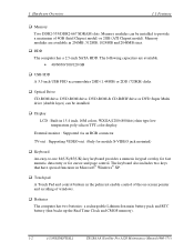
...; Optical Drive CD-ROM drive, DVD-ROM drive, DVD-ROM & CD-R/RW drive or DVD Super Multi drive (double layer) can be installed. ‰ Display LCD : Built-in 15.4 inch, 16M colors, WXGA(1280×800dots) thin type low temperature poly-silicon TFT color display. TV-out : Supporting VIDEO-out. (Only... The computer has two batteries: a rechargeable Lithium-Ion main battery pack and RTC battery (that backs up the Real Time Clock and CMOS memory). 1-2 [CONFIDENTIAL] TECRA A8 /Satellite Pro A120 Maintenance Manual (960-573)
...; Optical Drive CD-ROM drive, DVD-ROM drive, DVD-ROM & CD-R/RW drive or DVD Super Multi drive (double layer) can be installed. ‰ Display LCD : Built-in 15.4 inch, 16M colors, WXGA(1280×800dots) thin type low temperature poly-silicon TFT color display. TV-out : Supporting VIDEO-out. (Only... The computer has two batteries: a rechargeable Lithium-Ion main battery pack and RTC battery (that backs up the Real Time Clock and CMOS memory). 1-2 [CONFIDENTIAL] TECRA A8 /Satellite Pro A120 Maintenance Manual (960-573)
Maintenance Manual
Page 35
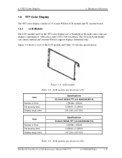
... (mm) Display range (mm) Specifications 15.4inch WXGA TFT (LG G33C0003G110) 1,280(W) x 800(H) 0.258(H) x 0.258(V) 331.2(H) x 207.0(V) Table 1-6 LCD module specifications (2/2) TECRA A8 /Satellite Pro A120 Maintenance Manual (960-573) [CONFIDENTIAL] 1-21 Figure 1-6 LCD module Table 1-6 LCD module specifications (1/2) Item Number of Dots Dot spacing (mm) Display range (mm) Specifications 15.4-inch WXGA TFT (LG...
... (mm) Display range (mm) Specifications 15.4inch WXGA TFT (LG G33C0003G110) 1,280(W) x 800(H) 0.258(H) x 0.258(V) 331.2(H) x 207.0(V) Table 1-6 LCD module specifications (2/2) TECRA A8 /Satellite Pro A120 Maintenance Manual (960-573) [CONFIDENTIAL] 1-21 Figure 1-6 LCD module Table 1-6 LCD module specifications (1/2) Item Number of Dots Dot spacing (mm) Display range (mm) Specifications 15.4-inch WXGA TFT (LG...
Maintenance Manual
Page 37
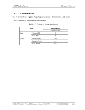
Table 1-7 FL inverter board specifications Input Output Item Voltage (VDC) Power (W) Voltage (Vrms) Current (mArms) Power (W/VA) Specifications G71C00011221 5 7 750 6.0 5/7 TECRA A8 /Satellite Pro A120 Maintenance Manual (960-573) [CONFIDENTIAL] 1-23 1.5 TFT Color Display 1 Hardware Overview 1.5.2 FL Inverter Board The FL inverter board supplies a high frequency current to illuminate the LCD module. Table 1-7 lists the FL inverter board specifications.
Table 1-7 FL inverter board specifications Input Output Item Voltage (VDC) Power (W) Voltage (Vrms) Current (mArms) Power (W/VA) Specifications G71C00011221 5 7 750 6.0 5/7 TECRA A8 /Satellite Pro A120 Maintenance Manual (960-573) [CONFIDENTIAL] 1-23 1.5 TFT Color Display 1 Hardware Overview 1.5.2 FL Inverter Board The FL inverter board supplies a high frequency current to illuminate the LCD module. Table 1-7 lists the FL inverter board specifications.
Maintenance Manual
Page 41
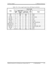
... 4.7 No No 5 No No 2.0-3.5 Yes Yes No batter y No No No No No No No No No No No Yes Object LED PSC FL-Inverter LCD CRT Docker AMP, Sound Power PC card PC card Sound CODEC, AMP PAD RTC TECRA A8 /Satellite Pro A120 Maintenance Manual (960-573) [CONFIDENTIAL] 1-27
... 4.7 No No 5 No No 2.0-3.5 Yes Yes No batter y No No No No No No No No No No No Yes Object LED PSC FL-Inverter LCD CRT Docker AMP, Sound Power PC card PC card Sound CODEC, AMP PAD RTC TECRA A8 /Satellite Pro A120 Maintenance Manual (960-573) [CONFIDENTIAL] 1-27

Maintenance Manual
Page 55
... 2: Error Code Check Procedure 3: Connection Check Procedure 4: Charge Check Procedure 5: Replacement Check Procedure 1 Icons in the LCD Check The following Icons in the LCD indicate the power supply status: ‰ Battery icon ‰ DC IN icon The Power Supply Controller (PSC) displays... the power supply status through the Battery icon and the DC IN icon in the LCD as instructed. The battery level is low while the system power is input. TECRA A8 /Satellite Pro A120 Maintenance Manual (960-573) [CONFIDENTIAL] 2-7 2.3 Power Supply Troubleshooting 2 Troubleshooting Procedures...
... 2: Error Code Check Procedure 3: Connection Check Procedure 4: Charge Check Procedure 5: Replacement Check Procedure 1 Icons in the LCD Check The following Icons in the LCD indicate the power supply status: ‰ Battery icon ‰ DC IN icon The Power Supply Controller (PSC) displays... the power supply status through the Battery icon and the DC IN icon in the LCD as instructed. The battery level is low while the system power is input. TECRA A8 /Satellite Pro A120 Maintenance Manual (960-573) [CONFIDENTIAL] 2-7 2.3 Power Supply Troubleshooting 2 Troubleshooting Procedures...
Maintenance Manual
Page 79
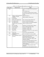
... & Reading of battery information F110 Waiting for VGA chip initialization completion, VGA BIOS initialization Update of system BIOS (Update of EDID information for LCD) Waiting VGA power on Waiting completion of display access F111 Call VGA BIOS F113 DISP_LOGO (Displaying logo) Start of waiting logo display DPORT=F125...Key input check during IRT (waiting here completion of KBC initialization) Input password (Waiting completion of HDD initialization) I/O LOCK process (model supporting I/O LOCK) TECRA A8 /Satellite Pro A120 Maintenance Manual (960-573) [CONFIDENTIAL] 2-31
... & Reading of battery information F110 Waiting for VGA chip initialization completion, VGA BIOS initialization Update of system BIOS (Update of EDID information for LCD) Waiting VGA power on Waiting completion of display access F111 Call VGA BIOS F113 DISP_LOGO (Displaying logo) Start of waiting logo display DPORT=F125...Key input check during IRT (waiting here completion of KBC initialization) Input password (Waiting completion of HDD initialization) I/O LOCK process (model supporting I/O LOCK) TECRA A8 /Satellite Pro A120 Maintenance Manual (960-573) [CONFIDENTIAL] 2-31
Maintenance Manual
Page 88
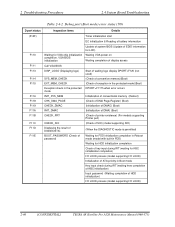
... initialization & Reading of battery information F110 Waiting for VGA chip initialization completion, VGA BIOS initialization Update of system BIOS (Update of EDID information for LCD) Waiting VGA power on Waiting completion of display access F111 Call VGA BIOS F113 DISP_LOGO (Displaying logo) Start of waiting logo display DPORT=F125 ...input check during IRT (waiting here completion of KBC initialization) Input password (Waiting completion of HDD initialization) I/O LOCK process (model supporting I/O LOCK) 2-40 [CONFIDENTIAL] TECRA A8 /Satellite Pro A120 Maintenance Manual (960-573)
... initialization & Reading of battery information F110 Waiting for VGA chip initialization completion, VGA BIOS initialization Update of system BIOS (Update of EDID information for LCD) Waiting VGA power on Waiting completion of display access F111 Call VGA BIOS F113 DISP_LOGO (Displaying logo) Start of waiting logo display DPORT=F125 ...input check during IRT (waiting here completion of KBC initialization) Input password (Waiting completion of HDD initialization) I/O LOCK process (model supporting I/O LOCK) 2-40 [CONFIDENTIAL] TECRA A8 /Satellite Pro A120 Maintenance Manual (960-573)
Maintenance Manual
Page 104
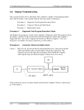
...Replacement Check Procedure 1 Diagnostic Test Program Execution Check The Display Test program is still an error, go to Procedure 3. 2-56 [CONFIDENTIAL] TECRA A8 /Satellite Pro A120 Maintenance Manual (960-573) Refer to determine if the computer's display is loose, reconnect firmly and restart the computer.... Procedure 2 Connector Check and Cable Check Check 1 The LCD, FL, FL Inverter Board and System Board are connected by the HV cable and LCD/FL cable as instructed. Insert the Diagnostics disk in Chapter 4, Replacement Procedures. The connectors...
...Replacement Check Procedure 1 Diagnostic Test Program Execution Check The Display Test program is still an error, go to Procedure 3. 2-56 [CONFIDENTIAL] TECRA A8 /Satellite Pro A120 Maintenance Manual (960-573) Refer to determine if the computer's display is loose, reconnect firmly and restart the computer.... Procedure 2 Connector Check and Cable Check Check 1 The LCD, FL, FL Inverter Board and System Board are connected by the HV cable and LCD/FL cable as instructed. Insert the Diagnostics disk in Chapter 4, Replacement Procedures. The connectors...
Maintenance Manual
Page 105
...instructions in Chapter 4, Replacement Procedures. 2.8 Display Troubleshooting 2 Troubleshooting Procedures Procedure 3 Replacement Check The FL, FL inverter board, LCD module, and system board are connected to Chapter 4, Replacement Procedures. If the problem still exists, perform Check 2. Check 2 ... following the instructions in Chapter 4, Replacement Procedures and test the display again. If the problem still exists, perform Check3. TECRA A8 /Satellite Pro A120 Maintenance Manual (960-573) [CONFIDENTIAL] 2-57 If the problem still exists, perform Check 4 Check ...
...instructions in Chapter 4, Replacement Procedures. 2.8 Display Troubleshooting 2 Troubleshooting Procedures Procedure 3 Replacement Check The FL, FL inverter board, LCD module, and system board are connected to Chapter 4, Replacement Procedures. If the problem still exists, perform Check 2. Check 2 ... following the instructions in Chapter 4, Replacement Procedures and test the display again. If the problem still exists, perform Check3. TECRA A8 /Satellite Pro A120 Maintenance Manual (960-573) [CONFIDENTIAL] 2-57 If the problem still exists, perform Check 4 Check ...


