

User Manual
Page 50
...10070; Flashes amber when the main battery charge is low and it is time to a live electrical outlet. Failure to connect or disconnect a power plug with wet hands. See "Changing the main battery" on page 128 for information on the indicator panel glows green. Disconnect the AC... this instruction could result in an electric shock, possibly resulting in the AC adaptor NOTE If the AC power light flashes amber during charging, either the main battery is malfunctioning, or it is not receiving correct input from the AC power supply. The AC power light on replacing the main battery.
...10070; Flashes amber when the main battery charge is low and it is time to a live electrical outlet. Failure to connect or disconnect a power plug with wet hands. See "Changing the main battery" on page 128 for information on the indicator panel glows green. Disconnect the AC... this instruction could result in an electric shock, possibly resulting in the AC adaptor NOTE If the AC power light flashes amber during charging, either the main battery is malfunctioning, or it is not receiving correct input from the AC power supply. The AC power light on replacing the main battery.
User Manual
Page 122
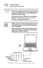
...charging, either the battery pack is malfunctioning, or it indicates that the system is not receiving correct input from the AC power supply. Disconnect the AC power cord/cable and remove the battery pack. See "Changing the main battery" on page 128 for information on certain models ...only) (Sample Illustration) Power and battery light locations Power button System Indicator Lights AC power light On/off light Battery light Hard disk drive light Wireless light SD light (on replacing the main battery...
...charging, either the battery pack is malfunctioning, or it indicates that the system is not receiving correct input from the AC power supply. Disconnect the AC power cord/cable and remove the battery pack. See "Changing the main battery" on page 128 for information on certain models ...only) (Sample Illustration) Power and battery light locations Power button System Indicator Lights AC power light On/off light Battery light Hard disk drive light Wireless light SD light (on replacing the main battery...

User Manual
Page 260
This appendix shows the shapes of the typical AC power cord/cable connectors for various parts of the world. USA and Canada United Kingdom UL approved CSA approved Australia AS approved BS approved Europe VDA approved NEMKO approved 260 Appendix B Power Cord/Cable Connectors Your notebook computer features a universal power supply you can use worldwide.
This appendix shows the shapes of the typical AC power cord/cable connectors for various parts of the world. USA and Canada United Kingdom UL approved CSA approved Australia AS approved BS approved Europe VDA approved NEMKO approved 260 Appendix B Power Cord/Cable Connectors Your notebook computer features a universal power supply you can use worldwide.
Maintenance Manual
Page 6
... 1.2 2.5-inch Hard Disk Drive 1-14 1.3 Keyboard...1-16 1.4 Optical Drive...1-17 1.5 TFT Color Display 1-21 1.6 Power Supply ...1-24 1.7 Batteries ...1-28 1.8 AC Adaptor...1-30 Chapter 2 Troubleshooting Procedures 2.1 Troubleshooting ...2-1 2.2 Troubleshooting Flowchart 2-3 2.3 Power Supply Troubleshooting 2-7 2.4 System Board Troubleshooting 2-21 2.5 USB FDD Troubleshooting 2-45 2.6 HDD Troubleshooting 2-48 2.7 Keyboard and ... 2.15 SD card Slot Troubleshooting 2-70 2.16 Fingerprint sensor Troubleshooting 2-71 vi [CONFIDENTIAL] TECRA A8 /Satellite Pro A120 Maintenance Manual (960-573)
... 1.2 2.5-inch Hard Disk Drive 1-14 1.3 Keyboard...1-16 1.4 Optical Drive...1-17 1.5 TFT Color Display 1-21 1.6 Power Supply ...1-24 1.7 Batteries ...1-28 1.8 AC Adaptor...1-30 Chapter 2 Troubleshooting Procedures 2.1 Troubleshooting ...2-1 2.2 Troubleshooting Flowchart 2-3 2.3 Power Supply Troubleshooting 2-7 2.4 System Board Troubleshooting 2-21 2.5 USB FDD Troubleshooting 2-45 2.6 HDD Troubleshooting 2-48 2.7 Keyboard and ... 2.15 SD card Slot Troubleshooting 2-70 2.16 Fingerprint sensor Troubleshooting 2-71 vi [CONFIDENTIAL] TECRA A8 /Satellite Pro A120 Maintenance Manual (960-573)
Maintenance Manual
Page 13
1 Hardware Overview Chapter 1 Contents 1.1 Features...1-1 1.2 2.5-inch Hard Disk Drive 1-14 1.3 Keyboard ...1-16 1.4 Optical Drive ...1-17 1.4.1 CD-ROM Drive 1-17 1.4.2 DVD-ROM Drive 1-18 1.4.3 DVD-ROM & CD-R/RW Drive 1-19 1.4.4 DVD-Super Multi Drive 1-20 1.5 TFT Color Display 1-21 1.5.1 LCD Module 1-21 1.5.2 FL Inverter Board 1-23 1.6 Power Supply...1-24 1.7 Batteries...1-28 1.7.1 Main Battery 1-28 1.7.2 RTC battery 1-29 1.8 AC Adaptor ...1-30 TECRA A8 /Satellite Pro A120 Maintenance Manual (960-573) [CONFIDENTIAL] 1-iii
1 Hardware Overview Chapter 1 Contents 1.1 Features...1-1 1.2 2.5-inch Hard Disk Drive 1-14 1.3 Keyboard ...1-16 1.4 Optical Drive ...1-17 1.4.1 CD-ROM Drive 1-17 1.4.2 DVD-ROM Drive 1-18 1.4.3 DVD-ROM & CD-R/RW Drive 1-19 1.4.4 DVD-Super Multi Drive 1-20 1.5 TFT Color Display 1-21 1.5.1 LCD Module 1-21 1.5.2 FL Inverter Board 1-23 1.6 Power Supply...1-24 1.7 Batteries...1-28 1.7.1 Main Battery 1-28 1.7.2 RTC battery 1-29 1.8 AC Adaptor ...1-30 TECRA A8 /Satellite Pro A120 Maintenance Manual (960-573) [CONFIDENTIAL] 1-iii
Maintenance Manual
Page 14
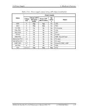
... specifications 1-21 FL inverter board specifications 1-23 Power supply output rating (Intel chipset model 1-25 Power supply output rating (ATI chipset model 1-26 Battery specifications 1-28 Time required for charges 1-28 Data preservation time 1-29 RTC battery charging/data preservation time 1-29 AC adapter specifications 1-30 1-iv [CONFIDENTIAL] TECRA A8 /Satellite Pro A120 Maintenance Manual (960...
... specifications 1-21 FL inverter board specifications 1-23 Power supply output rating (Intel chipset model 1-25 Power supply output rating (ATI chipset model 1-26 Battery specifications 1-28 Time required for charges 1-28 Data preservation time 1-29 RTC battery charging/data preservation time 1-29 AC adapter specifications 1-30 1-iv [CONFIDENTIAL] TECRA A8 /Satellite Pro A120 Maintenance Manual (960...

Maintenance Manual
Page 38
...: 1. Controls the display of battery icon and DC IN icon. 4. Turns the power supply on and off . 6. Judges that the DC power supply (AC adapter) is specified in Table 1-8-1 and 1-8-2. 1-24 [CONFIDENTIAL] TECRA A8 /Satellite Pro A120 Maintenance Manual (960-573) Detects DC output and circuit malfunctions. 3. 1 Hardware Overview 1.6 Power Supply 1.6 Power Supply The power supply supplies many different voltages to the computer. 2.
...: 1. Controls the display of battery icon and DC IN icon. 4. Turns the power supply on and off . 6. Judges that the DC power supply (AC adapter) is specified in Table 1-8-1 and 1-8-2. 1-24 [CONFIDENTIAL] TECRA A8 /Satellite Pro A120 Maintenance Manual (960-573) Detects DC output and circuit malfunctions. 3. 1 Hardware Overview 1.6 Power Supply 1.6 Power Supply The power supply supplies many different voltages to the computer. 2.
Maintenance Manual
Page 41
1.6 Power Supply 1 Hardware Overview Table 1-8-2 Power supply output rating (ATI chipset model)(2/2) Power supply Name M5V MCV FL-P5V PNL-P3V DDC-P5V IF-P5V SND-P5V MCVCCA-PYV MCVPPA-PYV A4R7-P4V SP-P5V R3V Voltag e[V] Power OFF (Suspend mode) Power OFF (Boot mode) 5 Yes Yes 5 Yes Yes 5 No No 3.3 No No 5 No No 5 No No 5 No No... Yes No batter y No No No No No No No No No No No Yes Object LED PSC FL-Inverter LCD CRT Docker AMP, Sound Power PC card PC card Sound CODEC, AMP PAD RTC TECRA A8 /Satellite Pro A120 Maintenance Manual (960-573) [CONFIDENTIAL] 1-27
1.6 Power Supply 1 Hardware Overview Table 1-8-2 Power supply output rating (ATI chipset model)(2/2) Power supply Name M5V MCV FL-P5V PNL-P3V DDC-P5V IF-P5V SND-P5V MCVCCA-PYV MCVPPA-PYV A4R7-P4V SP-P5V R3V Voltag e[V] Power OFF (Suspend mode) Power OFF (Boot mode) 5 Yes Yes 5 Yes Yes 5 No No 3.3 No No 5 No No 5 No No 5 No No... Yes No batter y No No No No No No No No No No No Yes Object LED PSC FL-Inverter LCD CRT Docker AMP, Sound Power PC card PC card Sound CODEC, AMP PAD RTC TECRA A8 /Satellite Pro A120 Maintenance Manual (960-573) [CONFIDENTIAL] 1-27
Maintenance Manual
Page 47
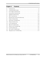
2 Troubleshooting Procedures Chapter 2 Contents 2.1 Troubleshooting...2-1 2.2 Troubleshooting Flowchart 2-3 2.3 Power Supply Troubleshooting 2-7 2.4 System Board Troubleshooting 2-21 2.5 USB FDD Troubleshooting 2-45 2.6 HDD Troubleshooting 2-48 2.7 Keyboard and Touch pad Troubleshooting 2-53 2.8 Display Troubleshooting 2-56 2.9 Optical... 2-63 2.13 Wireless LAN Troubleshooting 2-65 2.14 Sound Troubleshooting 2-67 2.15 SD card Slot Troubleshooting 2-70 2.16 Fingerprint sensor Troubleshooting 2-71 TECRA A8 /Satellite Pro A120 Maintenance Manual (960-573) [CONFIDENTIAL] 2-iii
2 Troubleshooting Procedures Chapter 2 Contents 2.1 Troubleshooting...2-1 2.2 Troubleshooting Flowchart 2-3 2.3 Power Supply Troubleshooting 2-7 2.4 System Board Troubleshooting 2-21 2.5 USB FDD Troubleshooting 2-45 2.6 HDD Troubleshooting 2-48 2.7 Keyboard and Touch pad Troubleshooting 2-53 2.8 Display Troubleshooting 2-56 2.9 Optical... 2-63 2.13 Wireless LAN Troubleshooting 2-65 2.14 Sound Troubleshooting 2-67 2.15 SD card Slot Troubleshooting 2-70 2.16 Fingerprint sensor Troubleshooting 2-71 TECRA A8 /Satellite Pro A120 Maintenance Manual (960-573) [CONFIDENTIAL] 2-iii
Maintenance Manual
Page 49
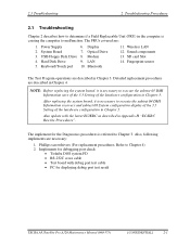
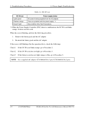
...08 System configuration display of the 3.3 Setting of the hardware configuration in Chapter 3. The FRUs covered are described in Chapter 4. Power Supply 2. Keyboard/Touch pad 6. Fingerprint sensor The Test Program operations are necessary: 1. LAN 10. Sound components 13. Display 7. ...for debugging port check • Toshiba DOS system FD • RS-232C cross cable • Test board with the latest EC/KBC as described in Appendix H "EC/KBC Rewrite Procedures". The implement for displaying debug port test result TECRA A8 /Satellite Pro A120 Maintenance Manual ...
...08 System configuration display of the 3.3 Setting of the hardware configuration in Chapter 3. The FRUs covered are described in Chapter 4. Power Supply 2. Keyboard/Touch pad 6. Fingerprint sensor The Test Program operations are necessary: 1. LAN 10. Sound components 13. Display 7. ...for debugging port check • Toshiba DOS system FD • RS-232C cross cable • Test board with the latest EC/KBC as described in Appendix H "EC/KBC Rewrite Procedures". The implement for displaying debug port test result TECRA A8 /Satellite Pro A120 Maintenance Manual ...
Maintenance Manual
Page 50
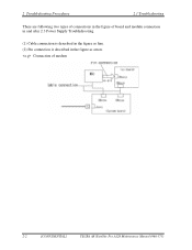
2 Troubleshooting Procedures 2.1 Troubleshooting There are following two types of connections in the figure as arrow. Connection of board and module connection in and after 2.3 Power Supply Troubleshooting. (1) Cable connection is described in the figure as line. (2) Pin connection is described in the figure of modem 2-2 [CONFIDENTIAL] TECRA A8 /Satellite Pro A120 Maintenance Manual (960-573)
2 Troubleshooting Procedures 2.1 Troubleshooting There are following two types of connections in the figure as arrow. Connection of board and module connection in and after 2.3 Power Supply Troubleshooting. (1) Cable connection is described in the figure as line. (2) Pin connection is described in the figure of modem 2-2 [CONFIDENTIAL] TECRA A8 /Satellite Pro A120 Maintenance Manual (960-573)

Maintenance Manual
Page 55
... DC IN icon in the tables below. To check the power supply status, install a battery pack and connect an AC adaptor. TECRA A8 /Satellite Pro A120 Maintenance Manual (960-573) [CONFIDENTIAL] 2-7 2.3 Power Supply Troubleshooting 2 Troubleshooting Procedures 2.3 Power Supply Troubleshooting The power supply controls many functions and components. To determine if the power supply is functioning properly, start with Procedure 1 and continue with...
... DC IN icon in the tables below. To check the power supply status, install a battery pack and connect an AC adaptor. TECRA A8 /Satellite Pro A120 Maintenance Manual (960-573) [CONFIDENTIAL] 2-7 2.3 Power Supply Troubleshooting 2 Troubleshooting Procedures 2.3 Power Supply Troubleshooting The power supply controls many functions and components. To determine if the power supply is functioning properly, start with Procedure 1 and continue with...
Maintenance Manual
Page 56
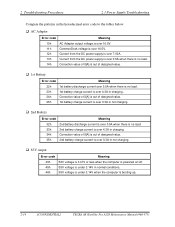
.... 1. 2 Troubleshooting Procedures 2.3 Power Supply Troubleshooting Table 2-2 DC IN icon DC IN icon Lights green Flashes orange Doesn't light Power supply status DC power is a problem with the power supply. *1 Any condition other than those... above , check the followings: Check 1 If the DC IN icon blinks orange, go to Procedure 2. There is being supplied from the AC adapter. NOTE: Use a supplied AC adapter G71C0004A510 (3-pin)/ G71C0002SC10 (2-pin). 2-8 [CONFIDENTIAL] TECRA A8...
.... 1. 2 Troubleshooting Procedures 2.3 Power Supply Troubleshooting Table 2-2 DC IN icon DC IN icon Lights green Flashes orange Doesn't light Power supply status DC power is a problem with the power supply. *1 Any condition other than those... above , check the followings: Check 1 If the DC IN icon blinks orange, go to Procedure 2. There is being supplied from the AC adapter. NOTE: Use a supplied AC adapter G71C0004A510 (3-pin)/ G71C0002SC10 (2-pin). 2-8 [CONFIDENTIAL] TECRA A8...
Maintenance Manual
Page 57
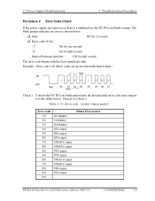
... Procedures Procedure 2 Error Code Check If the power supply microprocessor detects a malfunction, the DC IN icon blinks orange. Example: Error code 11h (Error codes are given in Intel chipset model) Error code 1*h 2*h 3*h 4*h 5*h 6*h 7*h 8*h 9*h A*h B*h C*h...65288;in hexadecimal format.) Check 1 Convert the DC IN icon blink pattern into the hexadecimal error code and compare it to Check 2. Where Error occurs TECRA A8 /Satellite Pro A120 Maintenance Manual (960-573) [CONFIDENTIAL] 2-9 The blink pattern indicates an error as shown below . Then go to the tables below...
... Procedures Procedure 2 Error Code Check If the power supply microprocessor detects a malfunction, the DC IN icon blinks orange. Example: Error code 11h (Error codes are given in Intel chipset model) Error code 1*h 2*h 3*h 4*h 5*h 6*h 7*h 8*h 9*h A*h B*h C*h...65288;in hexadecimal format.) Check 1 Convert the DC IN icon blink pattern into the hexadecimal error code and compare it to Check 2. Where Error occurs TECRA A8 /Satellite Pro A120 Maintenance Manual (960-573) [CONFIDENTIAL] 2-9 The blink pattern indicates an error as shown below . Then go to the tables below...
Maintenance Manual
Page 58
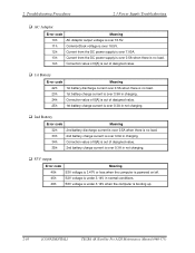
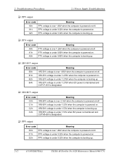
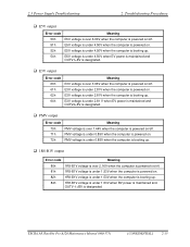
... 10h AC Adaptor output voltage is over 16.5V. 11h CommonDock voltage is over 16.5V. 12h Current from the DC power supply is over 7.00A. 13h Current from the DC power supply is over 0.5A when there is no load. 14h Correction value of 0[A] is out of designed value. ‰ 1st ... ‰ S3V output Error code Meaning 40h S3V voltage is 3.47V or less when the computer is powered on/off. 45h S3V voltage is under 3.14V in normal conditions. 46h S3V voltage is under 3.14V when the computer is booting up. 2-10 [CONFIDENTIAL] TECRA A8 /Satellite Pro A120 Maintenance Manual (960-573)
... 10h AC Adaptor output voltage is over 16.5V. 11h CommonDock voltage is over 16.5V. 12h Current from the DC power supply is over 7.00A. 13h Current from the DC power supply is over 0.5A when there is no load. 14h Correction value of 0[A] is out of designed value. ‰ 1st ... ‰ S3V output Error code Meaning 40h S3V voltage is 3.47V or less when the computer is powered on/off. 45h S3V voltage is under 3.14V in normal conditions. 46h S3V voltage is under 3.14V when the computer is booting up. 2-10 [CONFIDENTIAL] TECRA A8 /Satellite Pro A120 Maintenance Manual (960-573)
Maintenance Manual
Page 59
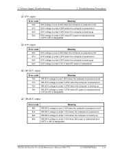
TECRA A8 /Satellite Pro A120 Maintenance Manual (960-573) [CONFIDENTIAL] 2-11 2.3 Power Supply Troubleshooting 2 Troubleshooting Procedures ‰ E5V output Error code Meaning 50h E5V voltage is over 6.00V when the computer is powered on/off. 51h E5V voltage is under 4.50V when the computer is powered on. 52h E5V voltage is ... ‰ E3V output Error code Meaning 60h E3V voltage is over 3.96V when the computer is powered on/off. 61h E3V voltage is under 2.81V when the computer is powered on. 62h E3V voltage is under 2.81V when the computer is booting up. 64h E3V voltage ...
TECRA A8 /Satellite Pro A120 Maintenance Manual (960-573) [CONFIDENTIAL] 2-11 2.3 Power Supply Troubleshooting 2 Troubleshooting Procedures ‰ E5V output Error code Meaning 50h E5V voltage is over 6.00V when the computer is powered on/off. 51h E5V voltage is under 4.50V when the computer is powered on. 52h E5V voltage is ... ‰ E3V output Error code Meaning 60h E3V voltage is over 3.96V when the computer is powered on/off. 61h E3V voltage is under 2.81V when the computer is powered on. 62h E3V voltage is under 2.81V when the computer is booting up. 64h E3V voltage ...
Maintenance Manual
Page 60
... when the computer is booting up. 2-12 [CONFIDENTIAL] TECRA A8 /Satellite Pro A120 Maintenance Manual (960-573) D2h PPV voltage is under 1.53V when the computer is booting up. 2 Troubleshooting Procedures 2.3 Power Supply Troubleshooting ‰ PPV output Error code Meaning 90h PPV ...voltage is over 1.80V when the computer is powered on/off. 91h PPV voltage is under 0.32V when the computer is powered on. 92h PPV voltage is ...
... when the computer is booting up. 2-12 [CONFIDENTIAL] TECRA A8 /Satellite Pro A120 Maintenance Manual (960-573) D2h PPV voltage is under 1.53V when the computer is booting up. 2 Troubleshooting Procedures 2.3 Power Supply Troubleshooting ‰ PPV output Error code Meaning 90h PPV ...voltage is over 1.80V when the computer is powered on/off. 91h PPV voltage is under 0.32V when the computer is powered on. 92h PPV voltage is ...
Maintenance Manual
Page 61
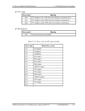
... is booting up. ‰ Miscellaneous Error code Meaning F0h The sub clock does not oscillate. 2.3 Power Supply Troubleshooting 2 Troubleshooting Procedures ‰ PTV output Error code Meaning E0h PTV voltage is over 1.26V when the computer is powered on . TECRA A8 /Satellite Pro A120 Maintenance Manual (960-573) [CONFIDENTIAL] 2-13 Table 2-3-2 Error code (in ATI chipset...-B1V output 9*h PPV output A*h PTV output B*h PMV output C*h 1R8-B1V output D*h PPV output E*h PTV output F*h - E1h PTV voltage is under 0.89V when the computer is powered on /off.
... is booting up. ‰ Miscellaneous Error code Meaning F0h The sub clock does not oscillate. 2.3 Power Supply Troubleshooting 2 Troubleshooting Procedures ‰ PTV output Error code Meaning E0h PTV voltage is over 1.26V when the computer is powered on . TECRA A8 /Satellite Pro A120 Maintenance Manual (960-573) [CONFIDENTIAL] 2-13 Table 2-3-2 Error code (in ATI chipset...-B1V output 9*h PPV output A*h PTV output B*h PMV output C*h 1R8-B1V output D*h PPV output E*h PTV output F*h - E1h PTV voltage is under 0.89V when the computer is powered on /off.
Maintenance Manual
Page 62
... 10h AC Adaptor output voltage is over 16.5V. 11h CommonDock voltage is over 16.5V. 12h Current from the DC power supply is over 7.00A. 13h Current from the DC power supply is over 0.5A when there is no load. 14h Correction value of 0[A] is out of designed value. ‰ 1st ... ‰ S3V output Error code Meaning 40h S3V voltage is 3.47V or less when the computer is powered on/off. 45h S3V voltage is under 3.14V in normal conditions. 46h S3V voltage is under 3.14V when the computer is booting up. 2-14 [CONFIDENTIAL] TECRA A8 /Satellite Pro A120 Maintenance Manual (960-573)
... 10h AC Adaptor output voltage is over 16.5V. 11h CommonDock voltage is over 16.5V. 12h Current from the DC power supply is over 7.00A. 13h Current from the DC power supply is over 0.5A when there is no load. 14h Correction value of 0[A] is out of designed value. ‰ 1st ... ‰ S3V output Error code Meaning 40h S3V voltage is 3.47V or less when the computer is powered on/off. 45h S3V voltage is under 3.14V in normal conditions. 46h S3V voltage is under 3.14V when the computer is booting up. 2-14 [CONFIDENTIAL] TECRA A8 /Satellite Pro A120 Maintenance Manual (960-573)
Maintenance Manual
Page 63
TECRA A8 /Satellite Pro A120 Maintenance Manual (960-573) [CONFIDENTIAL] 2-15 2.3 Power Supply Troubleshooting 2 Troubleshooting Procedures ‰ E5V output Error code Meaning 50h E5V voltage is over 6.00V when the computer is powered on/off. 51h E5V voltage is under 4.50V when the computer is powered on. 52h E5V voltage is .... ‰ PMV output Error code Meaning 70h PMV voltage is over 1.44V when the computer is powered on/off. 71h PMV voltage is under 0.85V when the computer is powered on. 72h PMV voltage is under 0.85V when the computer is booting up. ‰ 1R8-B1V...
TECRA A8 /Satellite Pro A120 Maintenance Manual (960-573) [CONFIDENTIAL] 2-15 2.3 Power Supply Troubleshooting 2 Troubleshooting Procedures ‰ E5V output Error code Meaning 50h E5V voltage is over 6.00V when the computer is powered on/off. 51h E5V voltage is under 4.50V when the computer is powered on. 52h E5V voltage is .... ‰ PMV output Error code Meaning 70h PMV voltage is over 1.44V when the computer is powered on/off. 71h PMV voltage is under 0.85V when the computer is powered on. 72h PMV voltage is under 0.85V when the computer is booting up. ‰ 1R8-B1V...


