

User Manual
Page 26
Contents Introduction 35 This guide 36 Safety icons 37 Other icons used 38 Other documentation 38 Service options 39 Chapter 1: Getting Started 40 Selecting a place to work 40 Creating a computer-friendly environment........40 Keeping yourself comfortable 41 Precautions 41 Important information on your computer's cooling fan 43 Setting up your computer 44 Setting up your software 45 Registering your computer with Toshiba 46 Adding optional external devices 47 Connecting to a power source 47 Charging the main battery 51 26
Contents Introduction 35 This guide 36 Safety icons 37 Other icons used 38 Other documentation 38 Service options 39 Chapter 1: Getting Started 40 Selecting a place to work 40 Creating a computer-friendly environment........40 Keeping yourself comfortable 41 Precautions 41 Important information on your computer's cooling fan 43 Setting up your computer 44 Setting up your software 45 Registering your computer with Toshiba 46 Adding optional external devices 47 Connecting to a power source 47 Charging the main battery 51 26
User Manual
Page 43
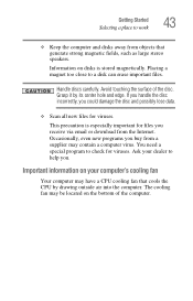
...the bottom of the disc. Grasp it by drawing outside air into the computer. This precaution is stored magnetically. Ask your computer's cooling fan Your computer may contain a computer virus. Information on your dealer to work 43 ❖ Keep the computer and disks away from a ...supplier may have a CPU cooling fan that generate strong magnetic fields, such as large stereo speakers. Avoid touching the surface of the computer. Placing a magnet too close to check...
...the bottom of the disc. Grasp it by drawing outside air into the computer. This precaution is stored magnetically. Ask your computer's cooling fan Your computer may contain a computer virus. Information on your dealer to work 43 ❖ Keep the computer and disks away from a ...supplier may have a CPU cooling fan that generate strong magnetic fields, such as large stereo speakers. Avoid touching the surface of the computer. Placing a magnet too close to check...
User Manual
Page 44
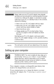
... make sure your PC and AC adaptor have adequate ventilation and are not limited to, a mouse, keyboard, printer, memory, and PC Cards. NOTE The cooling fan location will vary depending on a carpet or other soft material can use external power or to charge the battery you can block the vents. Your...
... make sure your PC and AC adaptor have adequate ventilation and are not limited to, a mouse, keyboard, printer, memory, and PC Cards. NOTE The cooling fan location will vary depending on a carpet or other soft material can use external power or to charge the battery you can block the vents. Your...
Maintenance Manual
Page 8
... pad...4-35 4.14 SD card slot...4-38 4.15 Bluetooth module...4-39 4.16 Serial/S-Video board 4-41 4.17 RTC battery ...4-42 4.18 Modem jack ...4-44 4.19 Fan...4-45 4.20 System board...4-47 4.21 Battery lock...4-49 4.22 HDD cable ...4-51 4.23 Heat sink/CPU ...4-52 4.24 PC card slot ...4-56 4.25 LCD... ...4-62 4.27 Display rear cover ...4-63 4.28 Wireless LAN antenna/Bluetooth antenna 4-65 4.29 Hinge...4-71 4.30 Speaker...4-73 4.31 Fluorescent Lamp...4-77 viii [CONFIDENTIAL] TECRA A8 /Satellite Pro A120 Maintenance Manual (960-573)
... pad...4-35 4.14 SD card slot...4-38 4.15 Bluetooth module...4-39 4.16 Serial/S-Video board 4-41 4.17 RTC battery ...4-42 4.18 Modem jack ...4-44 4.19 Fan...4-45 4.20 System board...4-47 4.21 Battery lock...4-49 4.22 HDD cable ...4-51 4.23 Heat sink/CPU ...4-52 4.24 PC card slot ...4-56 4.25 LCD... ...4-62 4.27 Display rear cover ...4-63 4.28 Wireless LAN antenna/Bluetooth antenna 4-65 4.29 Hinge...4-71 4.30 Speaker...4-73 4.31 Fluorescent Lamp...4-77 viii [CONFIDENTIAL] TECRA A8 /Satellite Pro A120 Maintenance Manual (960-573)
Maintenance Manual
Page 74
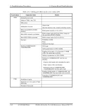
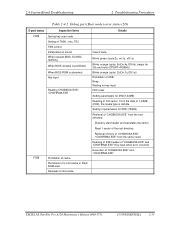
... directory. 2 Troubleshooting Procedures 2.4 System Board Troubleshooting Table 2-4-1 Debug port (Boot mode) error status (2/9) D port status Inspection items F009 Saving key scan code Setting of TASK_1ms_TSC FAN control Initialization of sound When request BIOS, EC/KBC rewriting When BIOS renewal is prohibited When BIOS ROM is abnormal Key input Reading CHGBIOSA.EXE... sector read. Setting of parameters for 2HD(1.44MB) Reading of first sector, If it is the data of "CHGBIOSA.EXE" and "CHGFIRMA.EXE" 2-26 [CONFIDENTIAL] TECRA A8 /Satellite Pro A120 Maintenance Manual (960-573)
... directory. 2 Troubleshooting Procedures 2.4 System Board Troubleshooting Table 2-4-1 Debug port (Boot mode) error status (2/9) D port status Inspection items F009 Saving key scan code Setting of TASK_1ms_TSC FAN control Initialization of sound When request BIOS, EC/KBC rewriting When BIOS renewal is prohibited When BIOS ROM is abnormal Key input Reading CHGBIOSA.EXE... sector read. Setting of parameters for 2HD(1.44MB) Reading of first sector, If it is the data of "CHGBIOSA.EXE" and "CHGFIRMA.EXE" 2-26 [CONFIDENTIAL] TECRA A8 /Satellite Pro A120 Maintenance Manual (960-573)
Maintenance Manual
Page 83
...2.4 System Board Troubleshooting 2 Troubleshooting Procedures Table 2-4-2 Debug port (Boot mode) error status (2/9) D port status Inspection items F009 Saving key scan code Setting of TASK_1ms_TSC FAN control Initialization of sound When request BIOS, EC/KBC rewriting When BIOS renewal is prohibited When BIOS ROM is abnormal Key input Reading CHGBIOSA.EXE... read. Directory start header and calculates the sector Read 1 sector of the root directory Retrieval of entry of "CHGBIOSA.EXE" and "CHGFIRMA.EXE" TECRA A8 /Satellite Pro A120 Maintenance Manual (960-573) [CONFIDENTIAL] 2-35
...2.4 System Board Troubleshooting 2 Troubleshooting Procedures Table 2-4-2 Debug port (Boot mode) error status (2/9) D port status Inspection items F009 Saving key scan code Setting of TASK_1ms_TSC FAN control Initialization of sound When request BIOS, EC/KBC rewriting When BIOS renewal is prohibited When BIOS ROM is abnormal Key input Reading CHGBIOSA.EXE... read. Directory start header and calculates the sector Read 1 sector of the root directory Retrieval of entry of "CHGBIOSA.EXE" and "CHGFIRMA.EXE" TECRA A8 /Satellite Pro A120 Maintenance Manual (960-573) [CONFIDENTIAL] 2-35
Maintenance Manual
Page 141
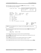
...press Enter. Selecting NO returns the process to DIAGNOSTIC TEST MENU : XXXXX : XX : XXX NOTE: The menu displayed by one shown above. TECRA A8 /Satellite Pro A120 Maintenance Manual (960-573) [CONFIDENTIAL] 3-7 Selecting YES of TEST LOOP increases the pass counter by your computer may be slightly...read 99 - ROM checksum 04 - Select the desired subtest number from the one , each time the test cycle ends and restarts the test cycle. Fan ON/OFF 05 - SYSTEM TEST, the following message will appear: SYSTEM TEST NAME XXXXXX xxxxxxx DIAGNOSTIC TEST VX.XX [Ctrl]+[Break] : test end...
...press Enter. Selecting NO returns the process to DIAGNOSTIC TEST MENU : XXXXX : XX : XXX NOTE: The menu displayed by one shown above. TECRA A8 /Satellite Pro A120 Maintenance Manual (960-573) [CONFIDENTIAL] 3-7 Selecting YES of TEST LOOP increases the pass counter by your computer may be slightly...read 99 - ROM checksum 04 - Select the desired subtest number from the one , each time the test cycle ends and restarts the test cycle. Fan ON/OFF 05 - SYSTEM TEST, the following message will appear: SYSTEM TEST NAME XXXXXX xxxxxxx DIAGNOSTIC TEST VX.XX [Ctrl]+[Break] : test end...
Maintenance Manual
Page 146
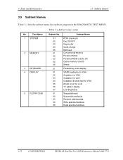
... 03 04 05 01 02 03 04 05 01 01 02 03 04 05 06 07 01 02 03 04 05 Subtest Name ROM checksum Fan ON/OFF Geyserville Quick charge DMI read Conventional memory Protected Mode Protected Mode (cache off) Cache memory (on/off) Stress Pressed key code display VRAM... the subtest names for LCD "H" pattern display LCD Brightness Sequential read Sequential read/write Random address/data Write specified address Read specified address 3-12 [CONFIDENTIAL] TECRA A8 /Satellite Pro A120 Maintenance Manual (960-573)
... 03 04 05 01 02 03 04 05 01 01 02 03 04 05 06 07 01 02 03 04 05 Subtest Name ROM checksum Fan ON/OFF Geyserville Quick charge DMI read Conventional memory Protected Mode Protected Mode (cache off) Cache memory (on/off) Stress Pressed key code display VRAM... the subtest names for LCD "H" pattern display LCD Brightness Sequential read Sequential read/write Random address/data Write specified address Read specified address 3-12 [CONFIDENTIAL] TECRA A8 /Satellite Pro A120 Maintenance Manual (960-573)

Maintenance Manual
Page 148
.... To check the GPU fan, press 2 and Enter. Fan number select (1;FAN#1(CPU), 2;FAN#2(GPU)*1, 0; After a while, the fan rotating will stop. *1 2;FAN#2(GPU)is not supported in this subtest checks that the CPU operating clock speed can be changed. 3-14 [CONFIDENTIAL] TECRA A8 /Satellite Pro A120 Maintenance ...Manual (960-573) The following message will appear. *** Test Fan Revolution Low speed Start Make sure the fan rotates at high speed, then press Enter. Move the highlight...
.... To check the GPU fan, press 2 and Enter. Fan number select (1;FAN#1(CPU), 2;FAN#2(GPU)*1, 0; After a while, the fan rotating will stop. *1 2;FAN#2(GPU)is not supported in this subtest checks that the CPU operating clock speed can be changed. 3-14 [CONFIDENTIAL] TECRA A8 /Satellite Pro A120 Maintenance ...Manual (960-573) The following message will appear. *** Test Fan Revolution Low speed Start Make sure the fan rotates at high speed, then press Enter. Move the highlight...
Maintenance Manual
Page 231
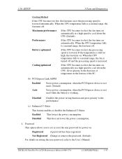
...the CPU. Enabled This lowers the power consumption. Cooling optimized If the CPU becomes too hot, the fan turns on or the processing speed is lowered automatically. TECRA A8 /Satellite Pro A120 Maintenance Manual (960-573) [CONFIDENTIAL] 3-97 If the temperature is working. Registered ...A password has been registered. Maximum performance If the CPU becomes too hot, the fan turns on automatically at a high ...
...the CPU. Enabled This lowers the power consumption. Cooling optimized If the CPU becomes too hot, the fan turns on or the processing speed is lowered automatically. TECRA A8 /Satellite Pro A120 Maintenance Manual (960-573) [CONFIDENTIAL] 3-97 If the temperature is working. Registered ...A password has been registered. Maximum performance If the CPU becomes too hot, the fan turns on automatically at a high ...
Maintenance Manual
Page 243
... pad...4-35 4.14 SD card slot...4-38 4.15 Bluetooth module...4-39 4.16 Serial/S-Video board 4-41 4.17 RTC battery ...4-42 4.18 Modem jack ...4-44 4.19 Fan...4-45 4.20 System board...4-47 4.21 Battery lock...4-49 4.22 HDD cable ...4-51 4.23 Heat sink/CPU ...4-52 4.24 PC card slot ...4-56 4.25 LCD.../FL inverter 4-57 4.26 Cover latch ...4-62 4.27 Display rear cover ...4-63 4.28 Wireless LAN antenna/Bluetooth antenna 4-65 4.29 Hinge...4-71 4.30 Speaker...4-73 TECRA A8 /Satellite Pro A120 Maintenance Manual (960-573) [CONFIDENTIAL] 2-iii
... pad...4-35 4.14 SD card slot...4-38 4.15 Bluetooth module...4-39 4.16 Serial/S-Video board 4-41 4.17 RTC battery ...4-42 4.18 Modem jack ...4-44 4.19 Fan...4-45 4.20 System board...4-47 4.21 Battery lock...4-49 4.22 HDD cable ...4-51 4.23 Heat sink/CPU ...4-52 4.24 PC card slot ...4-56 4.25 LCD.../FL inverter 4-57 4.26 Cover latch ...4-62 4.27 Display rear cover ...4-63 4.28 Wireless LAN antenna/Bluetooth antenna 4-65 4.29 Hinge...4-71 4.30 Speaker...4-73 TECRA A8 /Satellite Pro A120 Maintenance Manual (960-573) [CONFIDENTIAL] 2-iii
Maintenance Manual
Page 245
4 Replacement Procedures Figure 4-27 Removing the modem jack 4-44 Figure 4-28 Removing the fan 4-45 Figure 4-29 Removing the system board 4-47 Figure 4-30 Removing the battery lock 4-49 Figure 4-31 Removing the HDD cable 4-51 Figure 4-32 Removing ... Figure 4-47 to 4-54 Replacing LG.Philips fluorescent lamp (1) to (8 4-79 to 4-86 Figure 4-55 to 4-58 Replacing Samsung fluorescent lamp (1) to (4 4-87 to 4-89 TECRA A8 /Satellite Pro A120 Maintenance Manual (960-573) [CONFIDENTIAL] 2-v
4 Replacement Procedures Figure 4-27 Removing the modem jack 4-44 Figure 4-28 Removing the fan 4-45 Figure 4-29 Removing the system board 4-47 Figure 4-30 Removing the battery lock 4-49 Figure 4-31 Removing the HDD cable 4-51 Figure 4-32 Removing ... Figure 4-47 to 4-54 Replacing LG.Philips fluorescent lamp (1) to (8 4-79 to 4-86 Figure 4-55 to 4-58 Replacing Samsung fluorescent lamp (1) to (4 4-87 to 4-89 TECRA A8 /Satellite Pro A120 Maintenance Manual (960-573) [CONFIDENTIAL] 2-v
Maintenance Manual
Page 291
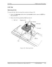
Remove the following screws and fan from the connector CN8771 on the system board. 2. Remove the glass tape and disconnect the fan cable from the slot. • M2.5×6C Tapping screw ×2 M2.5×6C Tapping Glass tape Fan cable CN8771 Fan Figure 4-28 Removing the fan TECRA A8 /Satellite Pro A120 Maintenance Manual (960-573) [CONFIDENTIAL] 4-45 4.19 Fan 4 Replacement Procedures 4.19 Fan Removing the Fan To remove the fan, follow the steps below and refer to Figure 4-28. 1.
Remove the following screws and fan from the connector CN8771 on the system board. 2. Remove the glass tape and disconnect the fan cable from the slot. • M2.5×6C Tapping screw ×2 M2.5×6C Tapping Glass tape Fan cable CN8771 Fan Figure 4-28 Removing the fan TECRA A8 /Satellite Pro A120 Maintenance Manual (960-573) [CONFIDENTIAL] 4-45 4.19 Fan 4 Replacement Procedures 4.19 Fan Removing the Fan To remove the fan, follow the steps below and refer to Figure 4-28. 1.
Maintenance Manual
Page 292
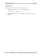
Install the fan to the connector CN8771 on the system board and stick the glass tape. 4-46 [CONFIDENTIAL] TECRA A8 /Satellite Pro A120 Maintenance Manual (960-573) Connect the fan cable to the slot and secure it with the following screws. • M2.5×6C Tapping screw ×2 2. 4 Replacement Procedures 4.19 Fan Installing the Fan To install the fan, follow the steps below and refer to Figure 4-28. 1.
Install the fan to the connector CN8771 on the system board and stick the glass tape. 4-46 [CONFIDENTIAL] TECRA A8 /Satellite Pro A120 Maintenance Manual (960-573) Connect the fan cable to the slot and secure it with the following screws. • M2.5×6C Tapping screw ×2 2. 4 Replacement Procedures 4.19 Fan Installing the Fan To install the fan, follow the steps below and refer to Figure 4-28. 1.
Maintenance Manual
Page 300
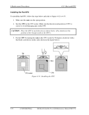
...shown in the figure below). Make sure the direction and position of the triangle mark on the CPU.) 3. Figure 4-34 Installing the CPU 4-54 [CONFIDENTIAL] TECRA A8 /Satellite Pro A120 Maintenance Manual (960-573) Seat the CPU in such direction as shown below and refer to Figure 4-32 to 4-35. 1. Make sure... to avoid damaging pins on the CPU socket by turning the cam on the CPU. 4 Replacement Procedures 4.23 Heat sink/CPU Installing the Fan/CPU To install the fan/CPU, follow the steps below . (Pay attention to the position of CPU is in the open position. 2. CAUTION: Place the CPU in...
...shown in the figure below). Make sure the direction and position of the triangle mark on the CPU.) 3. Figure 4-34 Installing the CPU 4-54 [CONFIDENTIAL] TECRA A8 /Satellite Pro A120 Maintenance Manual (960-573) Seat the CPU in such direction as shown below and refer to Figure 4-32 to 4-35. 1. Make sure... to avoid damaging pins on the CPU socket by turning the cam on the CPU. 4 Replacement Procedures 4.23 Heat sink/CPU Installing the Fan/CPU To install the fan/CPU, follow the steps below . (Pay attention to the position of CPU is in the open position. 2. CAUTION: Place the CPU in...
Maintenance Manual
Page 340
... C-22 C.25 CN8800 DC-IN connector (4-pin C-22 C.26 CN8810 Main Battery connector (10-pin C-22 C.27 CN9300 RTC Battery connector (3-pin C-22 C.28 CN8771 FAN interface connector (4-pin C-23 C.29 CN9600 SV board (FHBIR*) interface connector (20-pin C-23 C.30 CN9700 Fingerprint sensor board (FHBIS*) interface connector (6-pin)..........C-23 C.31... C-41 C.46 CN4610 USB 3 port connector (4-pin C-41 C.47 CN4611 USB 4 port connector (4-pin C-42 C.48 CN4612 USB 0 port connector (4-pin C-42 App-iv [CONFIDENTIAL] TECRA A8 /Satellite Pro A120 Maintenance Manual (960-573)
... C-22 C.25 CN8800 DC-IN connector (4-pin C-22 C.26 CN8810 Main Battery connector (10-pin C-22 C.27 CN9300 RTC Battery connector (3-pin C-22 C.28 CN8771 FAN interface connector (4-pin C-23 C.29 CN9600 SV board (FHBIR*) interface connector (20-pin C-23 C.30 CN9700 Fingerprint sensor board (FHBIS*) interface connector (6-pin)..........C-23 C.31... C-41 C.46 CN4610 USB 3 port connector (4-pin C-41 C.47 CN4611 USB 4 port connector (4-pin C-42 C.48 CN4612 USB 0 port connector (4-pin C-42 App-iv [CONFIDENTIAL] TECRA A8 /Satellite Pro A120 Maintenance Manual (960-573)
Maintenance Manual
Page 343
... C-22 Table C-25 DC-IN connector (4-pin C-22 Table C-26 Main Battery connector (10-pin C-22 Table C-27 RTC Battery connector (3-pin C-22 Table C-28 FAN interface connector (4-pin C-23 Table C-29 SV board (FHBIR*) interface connector (20-pin C-23 Table C-30 Fingerprint sensor board (FHBIS*) interface connector (6-pin C-23 Table... SV Board (FHBIR*) Table C-32 System board interface connector (20-pin C-25 Table C-33 S-Video connector (6-pin C-25 Table C-34 Serial interface connector (9-pin C-25 TECRA A8 /Satellite Pro A120 Maintenance Manual (960-573) [CONFIDENTIAL] App-vii
... C-22 Table C-25 DC-IN connector (4-pin C-22 Table C-26 Main Battery connector (10-pin C-22 Table C-27 RTC Battery connector (3-pin C-22 Table C-28 FAN interface connector (4-pin C-23 Table C-29 SV board (FHBIR*) interface connector (20-pin C-23 Table C-30 Fingerprint sensor board (FHBIS*) interface connector (6-pin C-23 Table... SV Board (FHBIR*) Table C-32 System board interface connector (20-pin C-25 Table C-33 S-Video connector (6-pin C-25 Table C-34 Serial interface connector (9-pin C-25 TECRA A8 /Satellite Pro A120 Maintenance Manual (960-573) [CONFIDENTIAL] App-vii
Maintenance Manual
Page 354
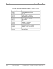
Appendices Appendix B Board Layout Table B-1 System board (FHBIS*/FHBAS*) connectors (front) Number CN3011 CN5000 CN9720 CN9721 CN9700 CN8771 CN9300 CN3230 CN3240 CN2600 CN4400 CN6170 CN3490 Name Modem cable relay connector LCD I/F connector ID*/AD* board I/F connector SW membrane I/F connector IS*/AS* board I/F connector Fan connector RTC battery connector Keyboard I/F connector Touchpad connector Wireless LAN card I/F connector Bluetooth module I/F connector Internal speaker connector Debugging port B-2 [CONFIDENTIAL] TECRA A8 /Satellite Pro A120 Maintenance Manual (960-573)
Appendices Appendix B Board Layout Table B-1 System board (FHBIS*/FHBAS*) connectors (front) Number CN3011 CN5000 CN9720 CN9721 CN9700 CN8771 CN9300 CN3230 CN3240 CN2600 CN4400 CN6170 CN3490 Name Modem cable relay connector LCD I/F connector ID*/AD* board I/F connector SW membrane I/F connector IS*/AS* board I/F connector Fan connector RTC battery connector Keyboard I/F connector Touchpad connector Wireless LAN card I/F connector Bluetooth module I/F connector Internal speaker connector Debugging port B-2 [CONFIDENTIAL] TECRA A8 /Satellite Pro A120 Maintenance Manual (960-573)


