
Operating Instructions
Page 1
...the space provided below. Owner's Record The model and serial numbers are located on your Sony dealer regarding this manual thoroughly, and retain it for future reference. DSC-P100/P120 © 2004 Sony Corporation 3-091-477-11(1) Getting started Shooting still images Viewing still images Deleting still ... Enjoying images on the bottom. Refer to these numbers whenever you call upon your computer_________ Troubleshooting Additional information Index DSC-P100/P120 Serial No. Digital Still Camera Operating Instructions Before operating the unit, please read this product.
...the space provided below. Owner's Record The model and serial numbers are located on your Sony dealer regarding this manual thoroughly, and retain it for future reference. DSC-P100/P120 © 2004 Sony Corporation 3-091-477-11(1) Getting started Shooting still images Viewing still images Deleting still ... Enjoying images on the bottom. Refer to these numbers whenever you call upon your computer_________ Troubleshooting Additional information Index DSC-P100/P120 Serial No. Digital Still Camera Operating Instructions Before operating the unit, please read this product.

Service Manual
Page 1
...Model E Model Hong Kong Model Australian Model Chinese Model Korea Model Tourist Model Japanese Model DSC-P100/P120 AEP Model UK Model Link SPECIFICATIONS SERVICE NOTE DISASSEMBLY Photo: DSC-P100/Silver BLOCK DIAGRAMS PRINTED WIRING BOARDS FRAME SCHEMATIC DIAGRAM REPAIR PARTS LIST SCHEMATIC DIAGRAMS • ... positions and procedures of the CH-146 and SY-104 boards are not shown. The following pages are not shown. DIGITAL STILL CAMERA Therefore, schematic diagram, printed wiring board and electrical parts list of processing the flexible boards/harnesses are shown. On the...
...Model E Model Hong Kong Model Australian Model Chinese Model Korea Model Tourist Model Japanese Model DSC-P100/P120 AEP Model UK Model Link SPECIFICATIONS SERVICE NOTE DISASSEMBLY Photo: DSC-P100/Silver BLOCK DIAGRAMS PRINTED WIRING BOARDS FRAME SCHEMATIC DIAGRAM REPAIR PARTS LIST SCHEMATIC DIAGRAMS • ... positions and procedures of the CH-146 and SY-104 boards are not shown. The following pages are not shown. DIGITAL STILL CAMERA Therefore, schematic diagram, printed wiring board and electrical parts list of processing the flexible boards/harnesses are shown. On the...
Service Manual
Page 2
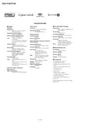
.../LS5B AC Adaptor (1) • Power cord (mains lead) (1) • NP-FR1 battery pack (DSC-P100:1, DSC- DSC-P100/P120 x Camera [System] Image device 9.04 mm (1/1.8 type) color CCD Primary color filter Total pixels number of camera Approx. 5 255 000 pixels Effective pixels number of camera Approx. 5 090 000 pixels Lens Carl Zeiss Vario-Tessar 3× zoom lens f = 7.9 - 23...
.../LS5B AC Adaptor (1) • Power cord (mains lead) (1) • NP-FR1 battery pack (DSC-P100:1, DSC- DSC-P100/P120 x Camera [System] Image device 9.04 mm (1/1.8 type) color CCD Primary color filter Total pixels number of camera Approx. 5 255 000 pixels Effective pixels number of camera Approx. 5 090 000 pixels Lens Carl Zeiss Vario-Tessar 3× zoom lens f = 7.9 - 23...
Service Manual
Page 6
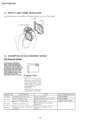
... ss: ss You can reverse the camera malfunction yourself. (However, contact your Sony dealer or local authorized Sony service facility when you cannot recover from the camera malfunction.) • E: ss: ss Contact your Sony dealer or local authorized Sony service facility. E:91:ss Checking of ...flash unit or replacement of flash unit. Lens frame M1.7 × 4 Lens block assembly 1-4. When failed in the focus and zoom initialization. DSC-P100/...
... ss: ss You can reverse the camera malfunction yourself. (However, contact your Sony dealer or local authorized Sony service facility when you cannot recover from the camera malfunction.) • E: ss: ss Contact your Sony dealer or local authorized Sony service facility. E:91:ss Checking of ...flash unit or replacement of flash unit. Lens frame M1.7 × 4 Lens block assembly 1-4. When failed in the focus and zoom initialization. DSC-P100/...

Service Manual
Page 12
CIRCUIT BOARDS LOCATION ST-105 flexible (including ST-102) MS-207 flexible SY-104 (including CH-146) CD-511 flexible JK-266 flexible CH-146 (included in SY-104) Board Name Function CD-511 flexible CCD IMAGER CH-146 CCD SIGNAL PROCESS (included in SY-104) JK-266 flexible DC IN, MULTI CONNECTOR MS-207 flexible MEMORY STICK CONNECTOR ST-102 FLASH DRIVE ST-105 flexible CHARGING CAPACITOR SY-104 CAMERA MODULE, CAMERA DSP, LENS DRIVE, (Including CH-146) SH DSP, FRONT CONTROL, LCD DRIVE, AUDIO, DC/DC CONVERTER 2-8E DSC-P100/P120 2-4.
CIRCUIT BOARDS LOCATION ST-105 flexible (including ST-102) MS-207 flexible SY-104 (including CH-146) CD-511 flexible JK-266 flexible CH-146 (included in SY-104) Board Name Function CD-511 flexible CCD IMAGER CH-146 CCD SIGNAL PROCESS (included in SY-104) JK-266 flexible DC IN, MULTI CONNECTOR MS-207 flexible MEMORY STICK CONNECTOR ST-102 FLASH DRIVE ST-105 flexible CHARGING CAPACITOR SY-104 CAMERA MODULE, CAMERA DSP, LENS DRIVE, (Including CH-146) SH DSP, FRONT CONTROL, LCD DRIVE, AUDIO, DC/DC CONVERTER 2-8E DSC-P100/P120 2-4.

Service Manual
Page 15
...10 8 13 10 17 11 20 20 7 19 11 21 19 132 124 3 123 126-129 84 36 135 CP101 CAMERA MODULE (1/9) 22 ı 35 45 46 48 CA AD00 - CA AD13 CA HD CAM F MCKTG CAM F 38 ...AB10 Y9 F1 AB9 AA10 AA9 D1 Y8 AB8 AA8 E1 AB7 AA7 Y7 C6 AB6 D7 AC8 IC301 CAMERA DSP, SDRAM (KWF BOARD) (2/9) G1 AC22 AC12 AC15 N3 K3 M4 K4 J3 T4 P4 U2...D14 K2 SYS V AA8 IC502 MC CAM, SH DSP, FLASH (4/9) MC XCS IC 301REG MC XCS IC 301SDRAM MC D0 - DSC-P100/P120 SECTION 3 3. OVERALL BLOCK DIAGRAM (1/2) ( ) : Number in parenthesis ( ) indicates the division number of schematic diagram where ...
...10 8 13 10 17 11 20 20 7 19 11 21 19 132 124 3 123 126-129 84 36 135 CP101 CAMERA MODULE (1/9) 22 ı 35 45 46 48 CA AD00 - CA AD13 CA HD CAM F MCKTG CAM F 38 ...AB10 Y9 F1 AB9 AA10 AA9 D1 Y8 AB8 AA8 E1 AB7 AA7 Y7 C6 AB6 D7 AC8 IC301 CAMERA DSP, SDRAM (KWF BOARD) (2/9) G1 AC22 AC12 AC15 N3 K3 M4 K4 J3 T4 P4 U2...D14 K2 SYS V AA8 IC502 MC CAM, SH DSP, FLASH (4/9) MC XCS IC 301REG MC XCS IC 301SDRAM MC D0 - DSC-P100/P120 SECTION 3 3. OVERALL BLOCK DIAGRAM (1/2) ( ) : Number in parenthesis ( ) indicates the division number of schematic diagram where ...

Service Manual
Page 18
DSC-P100/P120 3. BLOCK DIAGRAMS 3-4. POWER BLOCK DIAGRAM (2/2) ( ) : Number in parenthesis ( ) indicates the division number ...LCD MONITOR D901 CN002 BACKLIGHT 34 BL THH 35 BL H 32 BL L 3 BL THH 1 BL H 6 BL L CP101 CAMERA MODULE (1/9) IC004 3.3V REG 5 (8/9) 4 L102 L103 L104 FB105 FB102 FB103 CH-146 BOARD 54 55 71 53 IC101 52 CCD... L901 A 2.8V AU 2.8V IC901 AUDIO AMP (7/9) D 2.8V L301 D 1.2V L302 FB304 FB301 FB302 FB305 L303 IC302 VIDEO AMP (2/9) IC301 CAMERA DSP, SDRAM (KWF BOARD) (2/9) PI006 V4 PI007 V3 D 2.8V M 5V L502 XLENZ RST LED XZM RST LED D 2.8V D 2.8V ...
DSC-P100/P120 3. BLOCK DIAGRAMS 3-4. POWER BLOCK DIAGRAM (2/2) ( ) : Number in parenthesis ( ) indicates the division number ...LCD MONITOR D901 CN002 BACKLIGHT 34 BL THH 35 BL H 32 BL L 3 BL THH 1 BL H 6 BL L CP101 CAMERA MODULE (1/9) IC004 3.3V REG 5 (8/9) 4 L102 L103 L104 FB105 FB102 FB103 CH-146 BOARD 54 55 71 53 IC101 52 CCD... L901 A 2.8V AU 2.8V IC901 AUDIO AMP (7/9) D 2.8V L301 D 1.2V L302 FB304 FB301 FB302 FB305 L303 IC302 VIDEO AMP (2/9) IC301 CAMERA DSP, SDRAM (KWF BOARD) (2/9) PI006 V4 PI007 V3 D 2.8V M 5V L502 XLENZ RST LED XZM RST LED D 2.8V D 2.8V ...

Service Manual
Page 21
... scanning frame CRT picture frame Fig.b (Picture on monitor TV) When indicating parts by the heat. • Some chip part will be obtain. 4-2. SCHEMATIC DIAGRAMS DSC-P100/P120 4-2. Example C541 L452 22U 10UH TA A 2520 Kinds of capacitor Case Size External dimensions (mm) • Constants of the lens L = About 28 cm... (PTB-1450) 2. Line • J : IN/OUT direction of (+,-) B LINE. • C: adjustment for safety. They are measured between the measurement points and ground when camera shoots color bar chart of VOM used . b can be indicated as follows.
... scanning frame CRT picture frame Fig.b (Picture on monitor TV) When indicating parts by the heat. • Some chip part will be obtain. 4-2. SCHEMATIC DIAGRAMS DSC-P100/P120 4-2. Example C541 L452 22U 10UH TA A 2520 Kinds of capacitor Case Size External dimensions (mm) • Constants of the lens L = About 28 cm... (PTB-1450) 2. Line • J : IN/OUT direction of (+,-) B LINE. • C: adjustment for safety. They are measured between the measurement points and ground when camera shoots color bar chart of VOM used . b can be indicated as follows.

Service Manual
Page 22
... 0.1u 16V C105 0.1u 16V Q102 DTC144EMT2L SWITCH H VOUT NC GND GND GND VDD RG H2B H1B SUB CSUB NC VL H1A H2A NC 05 4-7 DSC-P100/P120 Precautions for Replacement of mounted on CD-511 flexible board can not be damaged by the side of the lens. SIGNAL PATH VIDEO SIGNAL...-511 flexible complete board and IC101 are not supplied, but there are mounted by static electricity from its structure, handle it carefully like for the camera section. • As the CCD imager may be measured, because they are included in CCD block assy.
... 0.1u 16V C105 0.1u 16V Q102 DTC144EMT2L SWITCH H VOUT NC GND GND GND VDD RG H2B H1B SUB CSUB NC VL H1A H2A NC 05 4-7 DSC-P100/P120 Precautions for Replacement of mounted on CD-511 flexible board can not be damaged by the side of the lens. SIGNAL PATH VIDEO SIGNAL...-511 flexible complete board and IC101 are not supplied, but there are mounted by static electricity from its structure, handle it carefully like for the camera section. • As the CCD imager may be measured, because they are included in CCD block assy.


