
Operating Instructions
Page 1
... No. Owner's Record The model and serial numbers are located on your Sony dealer regarding this manual thoroughly, and retain it for future reference. Digital Still Camera Operating Instructions Before operating the unit, please read this product. DSC-P100/P120 © 2004 Sony Corporation 3-091-477-11(1) Getting started Shooting still images Viewing still images Deleting...
... No. Owner's Record The model and serial numbers are located on your Sony dealer regarding this manual thoroughly, and retain it for future reference. Digital Still Camera Operating Instructions Before operating the unit, please read this product. DSC-P100/P120 © 2004 Sony Corporation 3-091-477-11(1) Getting started Shooting still images Viewing still images Deleting...

Operating Instructions
Page 2
... No.: 858-942-2230 This device complies with Part 15 of Conformity Trade Name: SONY Model No.: DSC-P100 Responsible Party: Sony Electronics Inc. Note: This equipment has been tested and found to comply with the limits for a Class B digital device, pursuant to which can radiate radio frequency energy and, if not installed and used...
... No.: 858-942-2230 This device complies with Part 15 of Conformity Trade Name: SONY Model No.: DSC-P100 Responsible Party: Sony Electronics Inc. Note: This equipment has been tested and found to comply with the limits for a Class B digital device, pursuant to which can radiate radio frequency energy and, if not installed and used...

Operating Instructions
Page 119
...+104°F) Storage temperature -20°C to +60°C (-4°F to change without notice. P120:2) • Battery case (DSC-P100:1, DSC-P120:2) • USB multi cable (1) • A/V multi cable (1) • Wrist strap (1) • "Memory Stick" (...32 MB) (1) • CD-ROM (USB driver SPVD-012) (1) • Operating instructions (1) • Soft carrying case (DSC-P120 only) (1) Design and specifications are subject to +140°F) Dimensions Approx. 48×29×81 mm (1 15/16...Power cord (mains lead) (1) • NP-FR1 battery pack (DSC-P100:1, DSC- Additional information 119
...+104°F) Storage temperature -20°C to +60°C (-4°F to change without notice. P120:2) • Battery case (DSC-P100:1, DSC-P120:2) • USB multi cable (1) • A/V multi cable (1) • Wrist strap (1) • "Memory Stick" (...32 MB) (1) • CD-ROM (USB driver SPVD-012) (1) • Operating instructions (1) • Soft carrying case (DSC-P120 only) (1) Design and specifications are subject to +140°F) Dimensions Approx. 48×29×81 mm (1 15/16...Power cord (mains lead) (1) • NP-FR1 battery pack (DSC-P100:1, DSC- Additional information 119

Service Manual
Page 1
... Model Link SPECIFICATIONS SERVICE NOTE DISASSEMBLY Photo: DSC-P100/Silver BLOCK DIAGRAMS PRINTED WIRING BOARDS FRAME SCHEMATIC DIAGRAM REPAIR PARTS LIST SCHEMATIC DIAGRAMS • For ADJUSTMENTS (SECTION 6), refer to SERVICE MANUAL, ADJ (987673451.pdf). • For INSTRUCTION MANUAL, refer to 4-42 Mounted parts location ....... DIGITAL STILL CAMERA Schematic diagram Pages 4-9 to 4-28 Printed wiring...
... Model Link SPECIFICATIONS SERVICE NOTE DISASSEMBLY Photo: DSC-P100/Silver BLOCK DIAGRAMS PRINTED WIRING BOARDS FRAME SCHEMATIC DIAGRAM REPAIR PARTS LIST SCHEMATIC DIAGRAMS • For ADJUSTMENTS (SECTION 6), refer to SERVICE MANUAL, ADJ (987673451.pdf). • For INSTRUCTION MANUAL, refer to 4-42 Mounted parts location ....... DIGITAL STILL CAMERA Schematic diagram Pages 4-9 to 4-28 Printed wiring...
Service Manual
Page 2
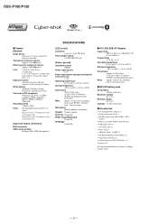
...) (1) • NP-FR1 battery pack (DSC-P100:1, DSC- P120:2) • Battery case (DSC-P100:1, DSC-P120:2) • USB multi cable (1) • A/V multi cable (1) • Wrist strap (1) • "Memory Stick" (32 MB) (1) • CD-ROM (USB driver SPVD-012) (1) • Operating instructions (1) • Soft carrying case (DSC-P120 only) (1) See page 5-13. DSC-P100/P120 x Camera [System] Image device 9.04 mm...
...) (1) • NP-FR1 battery pack (DSC-P100:1, DSC- P120:2) • Battery case (DSC-P100:1, DSC-P120:2) • USB multi cable (1) • A/V multi cable (1) • Wrist strap (1) • "Memory Stick" (32 MB) (1) • CD-ROM (USB driver SPVD-012) (1) • Operating instructions (1) • Soft carrying case (DSC-P120 only) (1) See page 5-13. DSC-P100/P120 x Camera [System] Image device 9.04 mm...

Service Manual
Page 3
DSC-P100/P120 SAFETY-RELATED COMPONENT WARNING!! REPLACE THESE COMPONENTS WITH SONY PARTS WHOSE PART NUMBERS APPEAR AS SHOWN IN THIS MANUAL OR IN SUPPLEMENTS PUBLISHED BY SONY. NE REMPLACER CES COMPOSANTS QUE PAR DES PIÈSES SONY DONT LES NUMÉROS SONT DONNÉS DANS CE MANUEL OU DANS LES SUPPÉMENTS... PUBLIÉS PAR SONY. Ordinary soldering irons can be used but unleaded solder may peel away if the heated tip is applied for unsoldered or poorly-soldered connections. ATTENTION ...
DSC-P100/P120 SAFETY-RELATED COMPONENT WARNING!! REPLACE THESE COMPONENTS WITH SONY PARTS WHOSE PART NUMBERS APPEAR AS SHOWN IN THIS MANUAL OR IN SUPPLEMENTS PUBLISHED BY SONY. NE REMPLACER CES COMPOSANTS QUE PAR DES PIÈSES SONY DONT LES NUMÉROS SONT DONNÉS DANS CE MANUEL OU DANS LES SUPPÉMENTS... PUBLIÉS PAR SONY. Ordinary soldering irons can be used but unleaded solder may peel away if the heated tip is applied for unsoldered or poorly-soldered connections. ATTENTION ...

Service Manual
Page 4
... BLOCK (SW), (RL 4-33 4-3. REPAIR PARTS LIST 5-1. Exploded Views 5-2 5-1-1. Note for Repair 1-1 1-2. Note in Lens Frame Installation 1-2 1-4. Mounted Parts Location 4-49 5. BT Holder Block Section 5-4 5-2. DSC-P100/P120 Section TABLE OF CONTENTS Title Page 1. Power Block Diagram (1/2 3-5 3-4. Remove Old Barrier Assy 2-6 2-3-3. Lens Block Section 5-3 5-1-3. Exchange Method of the ST-105 Flexible Board...
... BLOCK (SW), (RL 4-33 4-3. REPAIR PARTS LIST 5-1. Exploded Views 5-2 5-1-1. Note for Repair 1-1 1-2. Note in Lens Frame Installation 1-2 1-4. Mounted Parts Location 4-49 5. BT Holder Block Section 5-4 5-2. DSC-P100/P120 Section TABLE OF CONTENTS Title Page 1. Power Block Diagram (1/2 3-5 3-4. Remove Old Barrier Assy 2-6 2-3-3. Lens Block Section 5-3 5-1-3. Exchange Method of the ST-105 Flexible Board...
Service Manual
Page 5
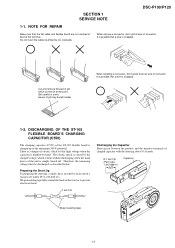
... at wire of gilt may be discharged as described below. It is possible that a wire is a danger of 1 kΩ /1 W (1-215-869-11). SECTION 1 SERVICE NOTE DSC-P100/P120 1-1. Preparing the Short Jig To preparing the short jig, a small clip is attached to prevent electrical shock. 1 kΩ/1 W Discharging the Capacitor Short-circuit between...
... at wire of gilt may be discharged as described below. It is possible that a wire is a danger of 1 kΩ /1 W (1-215-869-11). SECTION 1 SERVICE NOTE DSC-P100/P120 1-1. Preparing the Short Jig To preparing the short jig, a small clip is attached to prevent electrical shock. 1 kΩ/1 W Discharging the Capacitor Short-circuit between...
Service Manual
Page 6
... yourself. (However, contact your Sony dealer or local authorized Sony service facility when you cannot recover from the camera malfunction.) • E: ss: ss Contact your Sony dealer or local authorized Sony service facility. E:61:ss Checking of flash unit. E:91:ss Checking of flash unit or replacement of lens drive circuit. DSC-P100/P120 1-3. When failed in...
... yourself. (However, contact your Sony dealer or local authorized Sony service facility when you cannot recover from the camera malfunction.) • E: ss: ss Contact your Sony dealer or local authorized Sony service facility. E:61:ss Checking of flash unit. E:91:ss Checking of flash unit or replacement of lens drive circuit. DSC-P100/P120 1-3. When failed in...

Service Manual
Page 7
... flexible: CN706 2 Claw x2 3 ST-105 4 JK-266 flexible: CN704 5 Tapping screw (M1.7) x1 6 Control switch block (SW): CN703 7 MS-207 flexible: CN751 8 SY-104 2-1 2-2 DSC-P100/P120 HELP Note: High-voltage cautions R:1 kΩ/1 W Capacitor Discharging the Capacitor Short-circuit between the two (Part code: 1-215-869-11) points with the short...
... flexible: CN706 2 Claw x2 3 ST-105 4 JK-266 flexible: CN704 5 Tapping screw (M1.7) x1 6 Control switch block (SW): CN703 7 MS-207 flexible: CN751 8 SY-104 2-1 2-2 DSC-P100/P120 HELP Note: High-voltage cautions R:1 kΩ/1 W Capacitor Discharging the Capacitor Short-circuit between the two (Part code: 1-215-869-11) points with the short...

Service Manual
Page 8
DSC-P100/P120 2-2. CN003 5 6 Control switch block (SW) MS-207 flexible board SY-104 board JK-266 flexible board A/V multi cable Color monitor AC IN AC power adaptor 2-4 SY-104 BOARD SERVICE POSITION A 4 7 1 5 6 2 1 1 3 2 6 5 1 5 4 5 7 3 2 2 3 1 4 1 5 3 4 1 2 1 3 2 1 3 A 2 1 8 3 2 6 5 7 4 2-3 Panel block Lens block ST-105 flexible board To turn on/off the power, short the circuit between pin 5 and pin 6 (GND) of CN003 on Control switch block (SW) for 1 second.
DSC-P100/P120 2-2. CN003 5 6 Control switch block (SW) MS-207 flexible board SY-104 board JK-266 flexible board A/V multi cable Color monitor AC IN AC power adaptor 2-4 SY-104 BOARD SERVICE POSITION A 4 7 1 5 6 2 1 1 3 2 6 5 1 5 4 5 7 3 2 2 3 1 4 1 5 3 4 1 2 1 3 2 1 3 A 2 1 8 3 2 6 5 7 4 2-3 Panel block Lens block ST-105 flexible board To turn on/off the power, short the circuit between pin 5 and pin 6 (GND) of CN003 on Control switch block (SW) for 1 second.

Service Manual
Page 9
... tip of the group-1 frame and prize the ring. * Take extreme care so as not to weaken the adhesive force. into a notch of tweezers, etc. 2-3. DSC-P100/P120 1 2 3 2-3-1. EXCHANGE METHOD OF BARRIER ASSY Service parts Part Number 1 3-091-427-01 2 X-3954-476-1 3 3-086-156-31 Part Name Ring (A), Ornamental Barrier Assy Tapping...
... tip of the group-1 frame and prize the ring. * Take extreme care so as not to weaken the adhesive force. into a notch of tweezers, etc. 2-3. DSC-P100/P120 1 2 3 2-3-1. EXCHANGE METHOD OF BARRIER ASSY Service parts Part Number 1 3-091-427-01 2 X-3954-476-1 3 3-086-156-31 Part Name Ring (A), Ornamental Barrier Assy Tapping...

Service Manual
Page 10
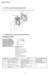
... the removed Barrier Assy. 2 1 1 * After removing the Barrier Assy, if the "G1 Dust-Proof Ring" was removed, it must be returned to the lens direction. DSC-P100/P120 2-3-2.
... the removed Barrier Assy. 2 1 1 * After removing the Barrier Assy, if the "G1 Dust-Proof Ring" was removed, it must be returned to the lens direction. DSC-P100/P120 2-3-2.

Service Manual
Page 11
Notch Adhesive Projection Adhesive Completion after 30 minutes. DSC-P100/P120 2-3-4. Put the 60g weight on the top surface of the Barrier Assy. * Do not apply too much adhesive. (Make quantity of adhesives into the ...
Notch Adhesive Projection Adhesive Completion after 30 minutes. DSC-P100/P120 2-3-4. Put the 60g weight on the top surface of the Barrier Assy. * Do not apply too much adhesive. (Make quantity of adhesives into the ...

Service Manual
Page 12
CIRCUIT BOARDS LOCATION ST-105 flexible (including ST-102) MS-207 flexible SY-104 (including CH-146) CD-511 flexible JK-266 flexible CH-146 (included in SY-104) Board Name Function CD-511 flexible CCD IMAGER CH-146 CCD SIGNAL PROCESS (included in SY-104) JK-266 flexible DC IN, MULTI CONNECTOR MS-207 flexible MEMORY STICK CONNECTOR ST-102 FLASH DRIVE ST-105 flexible CHARGING CAPACITOR SY-104 CAMERA MODULE, CAMERA DSP, LENS DRIVE, (Including CH-146) SH DSP, FRONT CONTROL, LCD DRIVE, AUDIO, DC/DC CONVERTER 2-8E DSC-P100/P120 2-4.
CIRCUIT BOARDS LOCATION ST-105 flexible (including ST-102) MS-207 flexible SY-104 (including CH-146) CD-511 flexible JK-266 flexible CH-146 (included in SY-104) Board Name Function CD-511 flexible CCD IMAGER CH-146 CCD SIGNAL PROCESS (included in SY-104) JK-266 flexible DC IN, MULTI CONNECTOR MS-207 flexible MEMORY STICK CONNECTOR ST-102 FLASH DRIVE ST-105 flexible CHARGING CAPACITOR SY-104 CAMERA MODULE, CAMERA DSP, LENS DRIVE, (Including CH-146) SH DSP, FRONT CONTROL, LCD DRIVE, AUDIO, DC/DC CONVERTER 2-8E DSC-P100/P120 2-4.

Service Manual
Page 13
SY spacer (MS) CN751 Shield sheet (SY) Battery holder assy HELP DSC-P100/P120 HELP Sheet attachment positions and procedures of processing the flexible boards/harnesses are shown.
SY spacer (MS) CN751 Shield sheet (SY) Battery holder assy HELP DSC-P100/P120 HELP Sheet attachment positions and procedures of processing the flexible boards/harnesses are shown.

Service Manual
Page 15
... 121 7 10 8 13 10 17 11 20 20 7 19 11 21 19 132 124 3 123 126-129 84 36 135 CP101 CAMERA MODULE (1/9) 22 ı 35 45 46 48 CA AD00 - A25 MC CKIO CAM F XFE CS XTG CS LENS TEMP VER EXT ...Y11 AB11 Y10 AA11 AB10 Y9 F1 AB9 AA10 AA9 D1 Y8 AB8 AA8 E1 AB7 AA7 Y7 C6 AB6 D7 AC8 IC301 CAMERA DSP, SDRAM (KWF BOARD) (2/9) G1 AC22 AC12 AC15 N3 K3 M4 K4 J3 T4 P4 U2 T3 D8 T2 AA12... 3-1. OVERALL BLOCK DIAGRAM (1/2) ( ) : Number in parenthesis ( ) indicates the division number of schematic diagram where the component is located. DSC-P100/P120 SECTION 3 3. D15 MC A1 -
... 121 7 10 8 13 10 17 11 20 20 7 19 11 21 19 132 124 3 123 126-129 84 36 135 CP101 CAMERA MODULE (1/9) 22 ı 35 45 46 48 CA AD00 - A25 MC CKIO CAM F XFE CS XTG CS LENS TEMP VER EXT ...Y11 AB11 Y10 AA11 AB10 Y9 F1 AB9 AA10 AA9 D1 Y8 AB8 AA8 E1 AB7 AA7 Y7 C6 AB6 D7 AC8 IC301 CAMERA DSP, SDRAM (KWF BOARD) (2/9) G1 AC22 AC12 AC15 N3 K3 M4 K4 J3 T4 P4 U2 T3 D8 T2 AA12... 3-1. OVERALL BLOCK DIAGRAM (1/2) ( ) : Number in parenthesis ( ) indicates the division number of schematic diagram where the component is located. DSC-P100/P120 SECTION 3 3. D15 MC A1 -

Service Manual
Page 16
... D8 ACV UNREG BL H BL L BL LEV 3 OVERALL (1/2) (PAGE 3-2) A : VIDEO SIGNAL A : AUDIO SIGNAL A : VIDEO/AUDIO SIGNAL J101 DC IN + BT901 S BATTERY TERMINAL − 3-3 3-4 BLOCK DIAGRAMS 3-2. DSC-P100/P120 3. OVERALL BLOCK DIAGRAM (2/2) ( ) : Number in parenthesis ( ) indicates the division number of schematic diagram where the component is located.
... D8 ACV UNREG BL H BL L BL LEV 3 OVERALL (1/2) (PAGE 3-2) A : VIDEO SIGNAL A : AUDIO SIGNAL A : VIDEO/AUDIO SIGNAL J101 DC IN + BT901 S BATTERY TERMINAL − 3-3 3-4 BLOCK DIAGRAMS 3-2. DSC-P100/P120 3. OVERALL BLOCK DIAGRAM (2/2) ( ) : Number in parenthesis ( ) indicates the division number of schematic diagram where the component is located.

Service Manual
Page 17
... D 1.2V M 5V ST 5V CAM 15.5V A 3.1V CAM -7.5V/-8.0V A POWER 2 (PAGE 3-7) PANEL 8.5V D003 BL H BL L BL THH BL LEV SYS DD ON 3-6 DSC-P100/P120 3. BLOCK DIAGRAMS 3-3.
... D 1.2V M 5V ST 5V CAM 15.5V A 3.1V CAM -7.5V/-8.0V A POWER 2 (PAGE 3-7) PANEL 8.5V D003 BL H BL L BL THH BL LEV SYS DD ON 3-6 DSC-P100/P120 3. BLOCK DIAGRAMS 3-3.

Service Manual
Page 18
DSC-P100/P120 3. BLOCK DIAGRAMS 3-4. SY-104 BOARD (2/2) ST UNREG L601 Q601, 602 ST 5V ST-105 FLEXIBLE ...COLOR LCD MONITOR D901 CN002 BACKLIGHT 34 BL THH 35 BL H 32 BL L 3 BL THH 1 BL H 6 BL L CP101 CAMERA MODULE (1/9) IC004 3.3V REG 5 (8/9) 4 L102 L103 L104 FB105 FB102 FB103 CH-146 BOARD 54 55 71 53 IC101 52 CCD...ON L901 A 2.8V AU 2.8V IC901 AUDIO AMP (7/9) D 2.8V L301 D 1.2V L302 FB304 FB301 FB302 FB305 L303 IC302 VIDEO AMP (2/9) IC301 CAMERA DSP, SDRAM (KWF BOARD) (2/9) PI006 V4 PI007 V3 D 2.8V M 5V L502 XLENZ RST LED XZM RST LED D 2.8V D 2.8V Q201...
DSC-P100/P120 3. BLOCK DIAGRAMS 3-4. SY-104 BOARD (2/2) ST UNREG L601 Q601, 602 ST 5V ST-105 FLEXIBLE ...COLOR LCD MONITOR D901 CN002 BACKLIGHT 34 BL THH 35 BL H 32 BL L 3 BL THH 1 BL H 6 BL L CP101 CAMERA MODULE (1/9) IC004 3.3V REG 5 (8/9) 4 L102 L103 L104 FB105 FB102 FB103 CH-146 BOARD 54 55 71 53 IC101 52 CCD...ON L901 A 2.8V AU 2.8V IC901 AUDIO AMP (7/9) D 2.8V L301 D 1.2V L302 FB304 FB301 FB302 FB305 L303 IC302 VIDEO AMP (2/9) IC301 CAMERA DSP, SDRAM (KWF BOARD) (2/9) PI006 V4 PI007 V3 D 2.8V M 5V L502 XLENZ RST LED XZM RST LED D 2.8V D 2.8V Q201...


