
Operating Instructions
Page 1
..., and retain it for future reference. Refer to these numbers whenever you call upon your computer_________ Troubleshooting Additional information Index DSC-P100/P120 © 2004 Sony Corporation 3-091-477-11(1) Getting started Shooting still images Viewing still images Deleting still images Before advanced operations Advanced still... PictBridge printer) Enjoying movies Enjoying images on the bottom. Record the serial number in the space provided below. DSC-P100/P120 Serial No. Digital Still Camera Operating Instructions Before operating the unit, please read this product.
..., and retain it for future reference. Refer to these numbers whenever you call upon your computer_________ Troubleshooting Additional information Index DSC-P100/P120 © 2004 Sony Corporation 3-091-477-11(1) Getting started Shooting still images Viewing still images Deleting still images Before advanced operations Advanced still... PictBridge printer) Enjoying movies Enjoying images on the bottom. Record the serial number in the space provided below. DSC-P100/P120 Serial No. Digital Still Camera Operating Instructions Before operating the unit, please read this product.

Operating Instructions
Page 2
...can radiate radio frequency energy and, if not installed and used with the equipment in order to comply with the limits for a digital device pursuant to radio or television reception, which the receiver is connected. - This symbol is encouraged to try to correct the ...has been tested and found to comply with the limits for a Class B digital device, pursuant to operate this manual could void your authority to Part 15 of Conformity Trade Name: SONY Model No.: DSC-P100 Responsible Party: Sony Electronics Inc. These limits are cautioned that interference will not occur in a...
...can radiate radio frequency energy and, if not installed and used with the equipment in order to comply with the limits for a digital device pursuant to radio or television reception, which the receiver is connected. - This symbol is encouraged to try to correct the ...has been tested and found to comply with the limits for a Class B digital device, pursuant to operate this manual could void your authority to Part 15 of Conformity Trade Name: SONY Model No.: DSC-P100 Responsible Party: Sony Electronics Inc. These limits are cautioned that interference will not occur in a...

Operating Instructions
Page 119
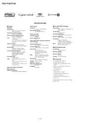
... DC 4.2 V Nominal voltage DC 3.6 V Capacity 4.4 Wh (1220 mAh) x Accessories • AC-LS5/LS5B AC Adaptor (1) • Power cord (mains lead) (1) • NP-FR1 battery pack (DSC-P100:1, DSC- Additional information 119 [Input and Output connectors] Multi connector USB communication Hi-Speed USB (USB 2.0 compliant) [LCD screen] LCD panel 4.6 cm (1.8 type) TFT drive Total...
... DC 4.2 V Nominal voltage DC 3.6 V Capacity 4.4 Wh (1220 mAh) x Accessories • AC-LS5/LS5B AC Adaptor (1) • Power cord (mains lead) (1) • NP-FR1 battery pack (DSC-P100:1, DSC- Additional information 119 [Input and Output connectors] Multi connector USB communication Hi-Speed USB (USB 2.0 compliant) [LCD screen] LCD panel 4.6 cm (1.8 type) TFT drive Total...

Service Manual
Page 1
...attachment positions and procedures of the CH-146 and SY-104 boards are not shown. DSC-P100/P120 SERVICE MANUAL Ver 1.0 2004.04 Revision History How to use Acrobat Reader 2 LEVEL DSC-P100 US Model Canadian Model E Model Hong Kong Model Australian Model Chinese Model Korea Model ...is premised the circuit board replacement service and not intended repair inside the CH-146 and SY-104 boards. The following pages are shown. DIGITAL STILL CAMERA Schematic diagram Pages 4-9 to 4-28 Printed wiring board Pages 4-39 to SERVICE MANUAL, LEVEL 1 (987673441.pdf). • Reference No...
...attachment positions and procedures of the CH-146 and SY-104 boards are not shown. DSC-P100/P120 SERVICE MANUAL Ver 1.0 2004.04 Revision History How to use Acrobat Reader 2 LEVEL DSC-P100 US Model Canadian Model E Model Hong Kong Model Australian Model Chinese Model Korea Model ...is premised the circuit board replacement service and not intended repair inside the CH-146 and SY-104 boards. The following pages are shown. DIGITAL STILL CAMERA Schematic diagram Pages 4-9 to 4-28 Printed wiring board Pages 4-39 to SERVICE MANUAL, LEVEL 1 (987673441.pdf). • Reference No...
Service Manual
Page 2
...(mains lead) (1) • NP-FR1 battery pack (DSC-P100:1, DSC- DSC-P100/P120 x Camera [System] Image device 9.04 mm (1/1.8 type) color CCD Primary color filter Total pixels number of camera Approx. 5 255 000 pixels Effective pixels number of camera Approx. 5 090 000 pixels Lens Carl Zeiss Vario-Tessar...176;F to +104°F) Storage temperature -20°C to +60°C (-4°F to change without notice. - 2 - P120:2) • Battery case (DSC-P100:1, DSC-P120:2) • USB multi cable (1) • A/V multi cable (1) • Wrist strap (1) • "Memory Stick" (32 MB) (1) • CD...
...(mains lead) (1) • NP-FR1 battery pack (DSC-P100:1, DSC- DSC-P100/P120 x Camera [System] Image device 9.04 mm (1/1.8 type) color CCD Primary color filter Total pixels number of camera Approx. 5 255 000 pixels Effective pixels number of camera Approx. 5 090 000 pixels Lens Carl Zeiss Vario-Tessar...176;F to +104°F) Storage temperature -20°C to +60°C (-4°F to change without notice. - 2 - P120:2) • Battery case (DSC-P100:1, DSC-P120:2) • USB multi cable (1) • A/V multi cable (1) • Wrist strap (1) • "Memory Stick" (32 MB) (1) • CD...

Service Manual
Page 3
... IC pins, etc. • Usable with ordinary solder It is at a temperature about 350°C. NE REMPLACER CES COMPOSANTS QUE PAR DES PIÈSES SONY DONT LES NUMÉROS SONT DONNÉS DANS CE MANUEL OU DANS LES SUPPÉMENTS PUBLIÉS PAR... circuit boards may also be set to about 40°C higher than ordinary solder so use caution not to the customer and recommend their replacement. 4. DSC-P100/P120 SAFETY-RELATED COMPONENT WARNING!! COMPONENTS IDENTIFIED BY MARK 0 OR DOTTED LINE WITH MARK 0 ON THE SCHEMATIC DIAGRAMS AND IN THE PARTS LIST ARE CRITICAL...
... IC pins, etc. • Usable with ordinary solder It is at a temperature about 350°C. NE REMPLACER CES COMPOSANTS QUE PAR DES PIÈSES SONY DONT LES NUMÉROS SONT DONNÉS DANS CE MANUEL OU DANS LES SUPPÉMENTS PUBLIÉS PAR... circuit boards may also be set to about 40°C higher than ordinary solder so use caution not to the customer and recommend their replacement. 4. DSC-P100/P120 SAFETY-RELATED COMPONENT WARNING!! COMPONENTS IDENTIFIED BY MARK 0 OR DOTTED LINE WITH MARK 0 ON THE SCHEMATIC DIAGRAMS AND IN THE PARTS LIST ARE CRITICAL...

Service Manual
Page 4
... Method of the ST-105 Flexible Board's Charging Capacitor (C550 1-1 1-3. Power Block Diagram (1/2 3-5 3-4. Note in Lens Frame Installation 1-2 1-4. Remove Old Barrier Assy 2-6 2-3-3. Cabinet Block Section 5-2 5-1-2. DSC-P100/P120 Section TABLE OF CONTENTS Title Page 1. Description on Self-diagnosis Display 1-2 2. DISASSEMBLY 2-1. SY-104 Board Service Position 2-3 2-3. Peel Off Old Ornamental Ring A 2-5 2-3-2. BLOCK DIAGRAMS...
... Method of the ST-105 Flexible Board's Charging Capacitor (C550 1-1 1-3. Power Block Diagram (1/2 3-5 3-4. Note in Lens Frame Installation 1-2 1-4. Remove Old Barrier Assy 2-6 2-3-3. Cabinet Block Section 5-2 5-1-2. DSC-P100/P120 Section TABLE OF CONTENTS Title Page 1. Description on Self-diagnosis Display 1-2 2. DISASSEMBLY 2-1. SY-104 Board Service Position 2-3 2-3. Peel Off Old Ornamental Ring A 2-5 2-3-2. BLOCK DIAGRAMS...
Service Manual
Page 5
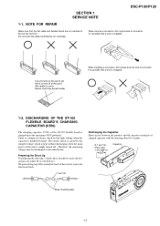
... must be left inside) When installing a connector, don't press down at wire of charged capacitor with the short jig about 10 seconds. SECTION 1 SERVICE NOTE DSC-P100/P120 1-1. Do not insert the cable insufficiently nor crookedly. When remove a connector, don't pull at the terminal. Cut and remove the part of gilt which...
... must be left inside) When installing a connector, don't press down at wire of charged capacitor with the short jig about 10 seconds. SECTION 1 SERVICE NOTE DSC-P100/P120 1-1. Do not insert the cable insufficiently nor crookedly. When remove a connector, don't pull at the terminal. Cut and remove the part of gilt which...
Service Manual
Page 6
... STICK ERROR - 1-2E DSC-P100/P120 1-3. DESCRIPTION ON SELF-DIAGNOSIS DISPLAY Self-diagnosis display • C: ss: ss You can reverse the camera malfunction yourself. (However, contact your Sony dealer or local authorized Sony service facility when you cannot recover from the camera malfunction.) • E: ss: ss Contact your Sony dealer or local authorized Sony service facility. Display Code...
... STICK ERROR - 1-2E DSC-P100/P120 1-3. DESCRIPTION ON SELF-DIAGNOSIS DISPLAY Self-diagnosis display • C: ss: ss You can reverse the camera malfunction yourself. (However, contact your Sony dealer or local authorized Sony service facility when you cannot recover from the camera malfunction.) • E: ss: ss Contact your Sony dealer or local authorized Sony service facility. Display Code...

Service Manual
Page 7
DSC-P100/P120 HELP Note: High-voltage cautions R:1 kΩ/1 W Capacitor Discharging the Capacitor Short-circuit between the two (Part code: 1-215-869-11) points with the short ...
DSC-P100/P120 HELP Note: High-voltage cautions R:1 kΩ/1 W Capacitor Discharging the Capacitor Short-circuit between the two (Part code: 1-215-869-11) points with the short ...

Service Manual
Page 8
CN003 5 6 Control switch block (SW) MS-207 flexible board SY-104 board JK-266 flexible board A/V multi cable Color monitor AC IN AC power adaptor 2-4 SY-104 BOARD SERVICE POSITION A 4 7 1 5 6 2 1 1 3 2 6 5 1 5 4 5 7 3 2 2 3 1 4 1 5 3 4 1 2 1 3 2 1 3 A 2 1 8 3 2 6 5 7 4 2-3 Panel block Lens block ST-105 flexible board To turn on/off the power, short the circuit between pin 5 and pin 6 (GND) of CN003 on Control switch block (SW) for 1 second. DSC-P100/P120 2-2.
CN003 5 6 Control switch block (SW) MS-207 flexible board SY-104 board JK-266 flexible board A/V multi cable Color monitor AC IN AC power adaptor 2-4 SY-104 BOARD SERVICE POSITION A 4 7 1 5 6 2 1 1 3 2 6 5 1 5 4 5 7 3 2 2 3 1 4 1 5 3 4 1 2 1 3 2 1 3 A 2 1 8 3 2 6 5 7 4 2-3 Panel block Lens block ST-105 flexible board To turn on/off the power, short the circuit between pin 5 and pin 6 (GND) of CN003 on Control switch block (SW) for 1 second. DSC-P100/P120 2-2.

Service Manual
Page 9
...'t use a soldering iron to damage the coated surface of Ornamental Ring A is about 60g Adhesive (Super X) (Note) Note: Use adhesive (Super X) or an equivalent article. DSC-P100/P120 1 2 3 2-3-1. In case of tweezers, etc.
...'t use a soldering iron to damage the coated surface of Ornamental Ring A is about 60g Adhesive (Super X) (Note) Note: Use adhesive (Super X) or an equivalent article. DSC-P100/P120 1 2 3 2-3-1. In case of tweezers, etc.

Service Manual
Page 10
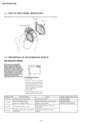
... two screws. * Tightening torque = 0.5 kgf Projection 1 2 2 2-6 This is an important part to prevent the dust and light from coming in relation to the lens direction. DSC-P100/P120 2-3-2. In returning the ring, adjust the location of the Barrier Assy in . * After removing the Barrier Assy, take extreme care not to the home...
... two screws. * Tightening torque = 0.5 kgf Projection 1 2 2 2-6 This is an important part to prevent the dust and light from coming in relation to the lens direction. DSC-P100/P120 2-3-2. In returning the ring, adjust the location of the Barrier Assy in . * After removing the Barrier Assy, take extreme care not to the home...

Service Manual
Page 11
... part. If the weight is put the weight on the mold part of the spring for preventing static electricity must be present in full circumference. 2-7 DSC-P100/P120 2-3-4.
... part. If the weight is put the weight on the mold part of the spring for preventing static electricity must be present in full circumference. 2-7 DSC-P100/P120 2-3-4.

Service Manual
Page 12
DSC-P100/P120 2-4. CIRCUIT BOARDS LOCATION ST-105 flexible (including ST-102) MS-207 flexible SY-104 (including CH-146) CD-511 flexible JK-266 flexible CH-146 (included in SY-104) Board Name Function CD-511 flexible CCD IMAGER CH-146 CCD SIGNAL PROCESS (included in SY-104) JK-266 flexible DC IN, MULTI CONNECTOR MS-207 flexible MEMORY STICK CONNECTOR ST-102 FLASH DRIVE ST-105 flexible CHARGING CAPACITOR SY-104 CAMERA MODULE, CAMERA DSP, LENS DRIVE, (Including CH-146) SH DSP, FRONT CONTROL, LCD DRIVE, AUDIO, DC/DC CONVERTER 2-8E
DSC-P100/P120 2-4. CIRCUIT BOARDS LOCATION ST-105 flexible (including ST-102) MS-207 flexible SY-104 (including CH-146) CD-511 flexible JK-266 flexible CH-146 (included in SY-104) Board Name Function CD-511 flexible CCD IMAGER CH-146 CCD SIGNAL PROCESS (included in SY-104) JK-266 flexible DC IN, MULTI CONNECTOR MS-207 flexible MEMORY STICK CONNECTOR ST-102 FLASH DRIVE ST-105 flexible CHARGING CAPACITOR SY-104 CAMERA MODULE, CAMERA DSP, LENS DRIVE, (Including CH-146) SH DSP, FRONT CONTROL, LCD DRIVE, AUDIO, DC/DC CONVERTER 2-8E

Service Manual
Page 13
DSC-P100/P120 HELP Sheet attachment positions and procedures of processing the flexible boards/harnesses are shown. SY spacer (MS) CN751 Shield sheet (SY) Battery holder assy HELP
DSC-P100/P120 HELP Sheet attachment positions and procedures of processing the flexible boards/harnesses are shown. SY spacer (MS) CN751 Shield sheet (SY) Battery holder assy HELP

Service Manual
Page 15
..., XCAM RST Y11 AB11 Y10 AA11 AB10 Y9 F1 AB9 AA10 AA9 D1 Y8 AB8 AA8 E1 AB7 AA7 Y7 C6 AB6 D7 AC8 IC301 CAMERA DSP, SDRAM (KWF BOARD) (2/9) G1 AC22 AC12 AC15 N3 K3 M4 K4 J3 T4 P4 U2 T3 D8 T2 AA12 U3 J23 AA19 J22 U20...; 125 119 18 118 121 7 10 8 13 10 17 11 20 20 7 19 11 21 19 132 124 3 123 126-129 84 36 135 CP101 CAMERA MODULE (1/9) 22 ı 35 45 46 48 CA AD00 - DSC-P100/P120 SECTION 3 3.
..., XCAM RST Y11 AB11 Y10 AA11 AB10 Y9 F1 AB9 AA10 AA9 D1 Y8 AB8 AA8 E1 AB7 AA7 Y7 C6 AB6 D7 AC8 IC301 CAMERA DSP, SDRAM (KWF BOARD) (2/9) G1 AC22 AC12 AC15 N3 K3 M4 K4 J3 T4 P4 U2 T3 D8 T2 AA12 U3 J23 AA19 J22 U20...; 125 119 18 118 121 7 10 8 13 10 17 11 20 20 7 19 11 21 19 132 124 3 123 126-129 84 36 135 CP101 CAMERA MODULE (1/9) 22 ı 35 45 46 48 CA AD00 - DSC-P100/P120 SECTION 3 3.

Service Manual
Page 16
OVERALL BLOCK DIAGRAM (2/2) ( ) : Number in parenthesis ( ) indicates the division number of schematic diagram where the component is located. DSC-P100/P120 3. BLOCK DIAGRAMS 3-2. SY-104 BOARD (2/2) V OUT OVERALL (1/2) (PAGE 3-2) 1 USBPHY D± AU AIN AU AOUT SYS SO, XSYS SCK XAU LINE MUTE AU SEN MELODY ...
OVERALL BLOCK DIAGRAM (2/2) ( ) : Number in parenthesis ( ) indicates the division number of schematic diagram where the component is located. DSC-P100/P120 3. BLOCK DIAGRAMS 3-2. SY-104 BOARD (2/2) V OUT OVERALL (1/2) (PAGE 3-2) 1 USBPHY D± AU AIN AU AOUT SYS SO, XSYS SCK XAU LINE MUTE AU SEN MELODY ...

Service Manual
Page 17
... D 1.2V M 5V ST 5V CAM 15.5V A 3.1V CAM -7.5V/-8.0V A POWER 2 (PAGE 3-7) PANEL 8.5V D003 BL H BL L BL THH BL LEV SYS DD ON 3-6 DSC-P100/P120
... D 1.2V M 5V ST 5V CAM 15.5V A 3.1V CAM -7.5V/-8.0V A POWER 2 (PAGE 3-7) PANEL 8.5V D003 BL H BL L BL THH BL LEV SYS DD ON 3-6 DSC-P100/P120

Service Manual
Page 18
...MONITOR D901 CN002 BACKLIGHT 34 BL THH 35 BL H 32 BL L 3 BL THH 1 BL H 6 BL L CP101 CAMERA MODULE (1/9) IC004 3.3V REG 5 (8/9) 4 L102 L103 L104 FB105 FB102 FB103 CH-146 BOARD 54 55 71 53 IC101 52... A 2.8V AU 2.8V IC901 AUDIO AMP (7/9) D 2.8V L301 D 1.2V L302 FB304 FB301 FB302 FB305 L303 IC302 VIDEO AMP (2/9) IC301 CAMERA DSP, SDRAM (KWF BOARD) (2/9) PI006 V4 PI007 V3 D 2.8V M 5V L502 XLENZ RST LED XZM RST LED D 2.8V D 2.... in parenthesis ( ) indicates the division number of schematic diagram where the component is located. DSC-P100/P120 3. BLOCK DIAGRAMS 3-4.
...MONITOR D901 CN002 BACKLIGHT 34 BL THH 35 BL H 32 BL L 3 BL THH 1 BL H 6 BL L CP101 CAMERA MODULE (1/9) IC004 3.3V REG 5 (8/9) 4 L102 L103 L104 FB105 FB102 FB103 CH-146 BOARD 54 55 71 53 IC101 52... A 2.8V AU 2.8V IC901 AUDIO AMP (7/9) D 2.8V L301 D 1.2V L302 FB304 FB301 FB302 FB305 L303 IC302 VIDEO AMP (2/9) IC301 CAMERA DSP, SDRAM (KWF BOARD) (2/9) PI006 V4 PI007 V3 D 2.8V M 5V L502 XLENZ RST LED XZM RST LED D 2.8V D 2.... in parenthesis ( ) indicates the division number of schematic diagram where the component is located. DSC-P100/P120 3. BLOCK DIAGRAMS 3-4.


