
Camera Operations Guide
Page 2
... returning your used rechargeable batteries to persons. This symbol is intended to alert the user to discontinue midway (fail), restart the application or disconnect and connect the communication cable (USB, etc.) again. 2 WARNING To prevent fire or shock hazard, do not expose the unit to rain or moisture.
... returning your used rechargeable batteries to persons. This symbol is intended to alert the user to discontinue midway (fail), restart the application or disconnect and connect the communication cable (USB, etc.) again. 2 WARNING To prevent fire or shock hazard, do not expose the unit to rain or moisture.
Camera Operations Guide
Page 3
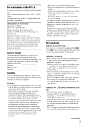
... device complies with Part 15 of Conformity Trade Name: SONY Model No.: DCR-TRV480 Responsible Party: Sony Electronics Inc. This equipment generates, uses, and can be...on the bottom. Regulatory Information Declaration of the FCC Rules. DCR-TRV Serial No. However, there is connected. - The supplied interface cable must accept any problems. • Compensation for a digital device...of recordings cannot be regulated if sold in a particular installation. For customers in Digital8 system only on your camcorder. Address: 16450 W. Bernardo Dr, San Diego, CA 92127 U.S.A. Model No....
... device complies with Part 15 of Conformity Trade Name: SONY Model No.: DCR-TRV480 Responsible Party: Sony Electronics Inc. This equipment generates, uses, and can be...on the bottom. Regulatory Information Declaration of the FCC Rules. DCR-TRV Serial No. However, there is connected. - The supplied interface cable must accept any problems. • Compensation for a digital device...of recordings cannot be regulated if sold in a particular installation. For customers in Digital8 system only on your camcorder. Address: 16450 W. Bernardo Dr, San Diego, CA 92127 U.S.A. Model No....
Camera Operations Guide
Page 4
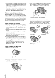
...8226; The screens shown in illustrating the operating procedures. Instructions with a USB or i.LINK cable, be damaged, or this manual are for long periods of time may cause a malfunction of your camcorder correctly. • When you insert the connector plug forcibly in the wrong direction, the ...depending on the back side of the LCD panel. • Do not hold the camcorder by the following illustration. 4 Then, touch the buttons displayed on connecting other device Before connecting your camcorder to press buttons on the LCD frame accidentally when you open or close the LCD ...
...8226; The screens shown in illustrating the operating procedures. Instructions with a USB or i.LINK cable, be damaged, or this manual are for long periods of time may cause a malfunction of your camcorder correctly. • When you insert the connector plug forcibly in the wrong direction, the ...depending on the back side of the LCD panel. • Do not hold the camcorder by the following illustration. 4 Then, touch the buttons displayed on connecting other device Before connecting your camcorder to press buttons on the LCD frame accidentally when you open or close the LCD ...
Camera Operations Guide
Page 15
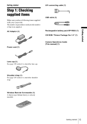
AC Adaptor (1) A/V connecting cable (1) USB cable (1) Rechargeable battery pack NP-FM30 (1) CD-ROM "Picture Package Ver.1.5" (1) Power cord (1) Camera Operations Guide (This manual) (1) Lens cap (1) See page 148 on how to ... number in parentheses indicates the number of that item supplied. Getting started Step 1: Checking supplied items Make sure you have following items supplied with your camcorder. Getting started Getting started 15
AC Adaptor (1) A/V connecting cable (1) USB cable (1) Rechargeable battery pack NP-FM30 (1) CD-ROM "Picture Package Ver.1.5" (1) Power cord (1) Camera Operations Guide (This manual) (1) Lens cap (1) See page 148 on how to ... number in parentheses indicates the number of that item supplied. Getting started Step 1: Checking supplied items Make sure you have following items supplied with your camcorder. Getting started Getting started 15
Camera Operations Guide
Page 59
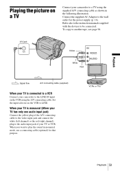
... also to the instruction manuals supplied with the devices to LINE. VCRs or TVs Playback 59 Playback Playing the picture on a TV Connect your camcorder to another tape, see page 90. A/V jack Yellow White Red Signal flow A/V connecting cable (supplied) When your TV is monaural (When your TV has only one audio input jack...
... also to the instruction manuals supplied with the devices to LINE. VCRs or TVs Playback 59 Playback Playing the picture on a TV Connect your camcorder to another tape, see page 90. A/V jack Yellow White Red Signal flow A/V connecting cable (supplied) When your TV is monaural (When your TV has only one audio input jack...

Camera Operations Guide
Page 82
... connect a USB cable (supplied) to your camcorder, and view the picture displayed on the screen of your camcorder on your computer (USB Streaming). During switching of systems, the screen turns blue, and the following displays appear on your camcorder. A/V c DV OUT You can connect ...a digital device and an analog device to your camcorder and convert the signal transmitted from the DV Interface of your camcorder. The analog signal input to the A/V jack of your camcorder will be heard. PB MODE For DCR-TRV480: GAUTO / Select to Digital8...
... connect a USB cable (supplied) to your camcorder, and view the picture displayed on the screen of your camcorder on your computer (USB Streaming). During switching of systems, the screen turns blue, and the following displays appear on your camcorder. A/V c DV OUT You can connect ...a digital device and an analog device to your camcorder and convert the signal transmitted from the DV Interface of your camcorder. The analog signal input to the A/V jack of your camcorder will be heard. PB MODE For DCR-TRV480: GAUTO / Select to Digital8...

Camera Operations Guide
Page 83
...GON OFF Select when using the Remote Commander supplied with the cassette inserted, and your camcorder calculates the remaining amount of your camcorder. Select to deactivate the Remote Commander to prevent your camcorder from your camcorder for about 8 seconds: • After you touch (play/pause). b Note &#... 57). DATA CODE GOFF DATE/TIME CAMERA DATA Select not to your computer. Using the Menu USB-PLY/EDT You can connect a USB cable (supplied) to display date, time and the camera settings data during playback. GSTD-USB PictBridge USB STREAM Select to display ...
...GON OFF Select when using the Remote Commander supplied with the cassette inserted, and your camcorder calculates the remaining amount of your camcorder. Select to deactivate the Remote Commander to prevent your camcorder from your camcorder for about 8 seconds: • After you touch (play/pause). b Note &#... 57). DATA CODE GOFF DATE/TIME CAMERA DATA Select not to your computer. Using the Menu USB-PLY/EDT You can connect a USB cable (supplied) to display date, time and the camera settings data during playback. GSTD-USB PictBridge USB STREAM Select to display ...
Camera Operations Guide
Page 89
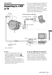
... sound separately. A/V jack Connecting with an i.LINK cable i.LINK cable (optional) i.LINK jack DV Interface Dubbing/Editing Yellow A/V connecting cable (supplied) Signal flow White Red VCRs or TVs b Notes • Use the A/V connecting cable to connect your camcorder to other device via the DV Interface. To use an i.LINK cable for connection Use an i.LINK cable (optional) to connect your camcorder to other devices.
... sound separately. A/V jack Connecting with an i.LINK cable i.LINK cable (optional) i.LINK jack DV Interface Dubbing/Editing Yellow A/V connecting cable (supplied) Signal flow White Red VCRs or TVs b Notes • Use the A/V connecting cable to connect your camcorder to other device via the DV Interface. To use an i.LINK cable for connection Use an i.LINK cable (optional) to connect your camcorder to other devices.
Camera Operations Guide
Page 90
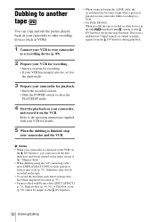
... mode. 3 Prepare your camcorder for details. 5 When the dubbing is finished, stop your camcorder and the VCR. • When connected using the i.LINK cable, the recorded picture becomes rough when a picture is paused on your camcorder while recording to a VCR. • For DCR-TRV480: When you cannot record the... title, indicators and words entered on the index screen of the "Memory Stick." • When dubbing using the A/V connecting cable, press DISPLAY/BATT INFO to hide ...
... mode. 3 Prepare your camcorder for details. 5 When the dubbing is finished, stop your camcorder and the VCR. • When connected using the i.LINK cable, the recorded picture becomes rough when a picture is paused on your camcorder while recording to a VCR. • For DCR-TRV480: When you cannot record the... title, indicators and words entered on the index screen of the "Memory Stick." • When dubbing using the A/V connecting cable, press DISPLAY/BATT INFO to hide ...
Camera Operations Guide
Page 91
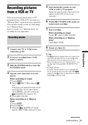
...8226; The indicator appears when you connect your camcorder and other devices via an i.LINK cable. (This indicator may also appear on your TV.) • When recording movies on a "Memory Stick," you can skip step 4 and press REC START/STOP in step 6. • For DCR-TRV480: To enable smooth transition, we recommend... 91 If you do not mix pictures recorded in the Hi8 / standard 8 mm system on other devices with the Digital8 system on a tape or a "Memory Stick" inserted in your camcorder. 6 Touch [REC START] at the point you are recording from the (EDIT/PLAY) menu (p. 76). 3 ...
...8226; The indicator appears when you connect your camcorder and other devices via an i.LINK cable. (This indicator may also appear on your TV.) • When recording movies on a "Memory Stick," you can skip step 4 and press REC START/STOP in step 6. • For DCR-TRV480: To enable smooth transition, we recommend... 91 If you do not mix pictures recorded in the Hi8 / standard 8 mm system on other devices with the Digital8 system on a tape or a "Memory Stick" inserted in your camcorder. 6 Touch [REC START] at the point you are recording from the (EDIT/PLAY) menu (p. 76). 3 ...

Camera Operations Guide
Page 95
...Touch [EDIT SET]. indicators and words entered on to "Step 2 : Adjusting the synchronization of the "Memory Stick." 1 Connect your camcorder (playing device). • Insert a cassette for recording. • Set the input selector to input mode if your ...camcorder as a recording device (p. 89). SPD PB REC CTRL PROG. EDIT], then touch . EDIT EDIT SET CON- OUT 10Touch [CONTROL]. EDIT REC CTRL OK (EDIT/ 7 Touch / to make the connection. OTHER DEVICE MEMORY STICK 8 Touch [OTHER DEVICE]. TROL 1/2 CUT- PROG. The dubbing procedure is easier with an A/V connecting cable...
...Touch [EDIT SET]. indicators and words entered on to "Step 2 : Adjusting the synchronization of the "Memory Stick." 1 Connect your camcorder (playing device). • Insert a cassette for recording. • Set the input selector to input mode if your ...camcorder as a recording device (p. 89). SPD PB REC CTRL PROG. EDIT], then touch . EDIT EDIT SET CON- OUT 10Touch [CONTROL]. EDIT REC CTRL OK (EDIT/ 7 Touch / to make the connection. OTHER DEVICE MEMORY STICK 8 Touch [OTHER DEVICE]. TROL 1/2 CUT- PROG. The dubbing procedure is easier with an A/V connecting cable...

Camera Operations Guide
Page 96
...most appropriate one code listed for details on operation. 5 Point the infrared ray emitter of your camcorder towards the remote sensor on your VCR, then touch . Remote sensor Infrared ray emitter VCR A/V connecting cable (supplied) 1 Touch , then [IR SETUP]. 2 Select the [IR SETUP] code of ...[Completed.] appears when the [IR SETUP] code test is set at "3" as the default setting.) Manufacturing company [IR SETUP] code Sony 1, 2, 3, 4, 5, 6 Admiral (M. Go on your camcorder by your VCR, refer to "[IR SETUP] code list" (p. 96). When there is more than one . 3 Touch [PAUSEMODE]. ...
...most appropriate one code listed for details on operation. 5 Point the infrared ray emitter of your camcorder towards the remote sensor on your VCR, then touch . Remote sensor Infrared ray emitter VCR A/V connecting cable (supplied) 1 Touch , then [IR SETUP]. 2 Select the [IR SETUP] code of ...[Completed.] appears when the [IR SETUP] code test is set at "3" as the default setting.) Manufacturing company [IR SETUP] code Sony 1, 2, 3, 4, 5, 6 Admiral (M. Go on your camcorder by your VCR, refer to "[IR SETUP] code list" (p. 96). When there is more than one . 3 Touch [PAUSEMODE]. ...
Camera Operations Guide
Page 99
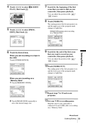
... SCENE 0 END 2 Touch [IMAGE SIZE] repeatedly to select the desired image size. 7 Search for the end of the program mark changes to record on your camcorder, then pause playback. PROG. PROG. Dubbing/Editing 4 Touch / to select [PROG. EDIT REC CTRL OK (EDIT/ 5 Touch / to select PLAY), then touch ....ED I T SET UNDO TOTAL 0:00:00:00 SCENE 0 END When you want to light blue. The starting point of the first program is connected via an i.LINK cable or recording on a "Memory Stick." EDIT MARK OUT START 0:00:00:00 ED I T SET UNDO TOTAL 0:00:00:12 SCENE 1 END...
... SCENE 0 END 2 Touch [IMAGE SIZE] repeatedly to select the desired image size. 7 Search for the end of the program mark changes to record on your camcorder, then pause playback. PROG. PROG. Dubbing/Editing 4 Touch / to select [PROG. EDIT REC CTRL OK (EDIT/ 5 Touch / to select PLAY), then touch ....ED I T SET UNDO TOTAL 0:00:00:00 SCENE 0 END When you want to light blue. The starting point of the first program is connected via an i.LINK cable or recording on a "Memory Stick." EDIT MARK OUT START 0:00:00:00 ED I T SET UNDO TOTAL 0:00:00:12 SCENE 1 END...
Camera Operations Guide
Page 100
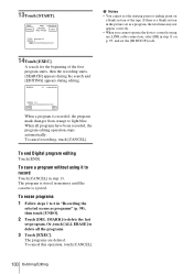
... stops automatically. To cancel this operation, touch [CANCEL]. 100 Dubbing/Editing A search for the beginning of the tape. To save a program without using an i.LINK cable connection, select [IR] in step 13. The programs are deleted. START CANCEL 0:00:00:00 ENGAGE REC PAUSE EXEC TOTAL 0:00:00:25 SCENE 3 b Notes •...
... stops automatically. To cancel this operation, touch [CANCEL]. 100 Dubbing/Editing A search for the beginning of the tape. To save a program without using an i.LINK cable connection, select [IR] in step 13. The programs are deleted. START CANCEL 0:00:00:00 ENGAGE REC PAUSE EXEC TOTAL 0:00:00:25 SCENE 3 b Notes •...
Camera Operations Guide
Page 104
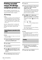
... not set to the wall outlet for details on the "Memory Stick" will be printed by the Camera & Imaging Products Association (CIPA). Connecting your camcorder to a printer using the supplied USB cable. Printing recorded images (PictBridge compliant printer) With a PictBridge compatible printer, you can print still images without using a computer. Follow the instructions...
... not set to the wall outlet for details on the "Memory Stick" will be printed by the Camera & Imaging Products Association (CIPA). Connecting your camcorder to a printer using the supplied USB cable. Printing recorded images (PictBridge compliant printer) With a PictBridge compatible printer, you can print still images without using a computer. Follow the instructions...

Camera Operations Guide
Page 105
... with a device other power modes. - A confirmation screen appears. The operations may not support the date printing function. Removing the "Memory Stick" from your camcorder and printer. Keep USB cable connected. PRINT 101-0001 1 / 10 101 Print this? To stop printing Touch [CANCEL] while printing. Dubbing/Editing 105 The default setting is finished, [Printing...
... with a device other power modes. - A confirmation screen appears. The operations may not support the date printing function. Removing the "Memory Stick" from your camcorder and printer. Keep USB cable connected. PRINT 101-0001 1 / 10 101 Print this? To stop printing Touch [CANCEL] while printing. Dubbing/Editing 105 The default setting is finished, [Printing...

Camera Operations Guide
Page 116
... source. 3 On the LCD panel, touch t [MENU] t [ (STANDARD SET)] t [A/V t DV OUT] t [ON] t . 116 Using with your camcorder - White Red VCRs or TVs 1 Turn on your camcorder. Digital convert function A/V jack Using the A/V connecting cable (supplied) and an i.LINK cable (optional), you can record the video signal must be installed on the analog video unit. 2 Slide...
... source. 3 On the LCD panel, touch t [MENU] t [ (STANDARD SET)] t [A/V t DV OUT] t [ON] t . 116 Using with your camcorder - White Red VCRs or TVs 1 Turn on your camcorder. Digital convert function A/V jack Using the A/V connecting cable (supplied) and an i.LINK cable (optional), you can record the video signal must be installed on the analog video unit. 2 Slide...
Camera Operations Guide
Page 122
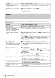
...sound is heard appropriately. (p. 81) cMake sure the red and white plugs of the A/V connecting cable are connected. (p. 59) The sound breaks off. cSet [MULTI-SOUND] to select . This is ...Digital8 system. (p. 82) "---" is heard. cClean the head using the cleaning cassette (optional). (p. 143) No sound or only a low sound is displayed on other devices in Hi8 /standard 8 mm system. (p. 82) cFor DCR-TRV480...or middle of the tape. cIf the problem persists, contact your Sony dealer or local authorized Sony service facility. screen. This is not played back correctly. Cause ...
...sound is heard appropriately. (p. 81) cMake sure the red and white plugs of the A/V connecting cable are connected. (p. 59) The sound breaks off. cSet [MULTI-SOUND] to select . This is ...Digital8 system. (p. 82) "---" is heard. cClean the head using the cleaning cassette (optional). (p. 143) No sound or only a low sound is displayed on other devices in Hi8 /standard 8 mm system. (p. 82) cFor DCR-TRV480...or middle of the tape. cIf the problem persists, contact your Sony dealer or local authorized Sony service facility. screen. This is not played back correctly. Cause ...

Camera Operations Guide
Page 144
... appear on the screen during recording. When you have rotated the LCD panel and set it may cause damage. • If your camcorder, then disconnect any connecting cables except the AC Adaptor from step 4 again. On handling the casing • If the casing is used in the following to avoid...while pressing DISPLAY/BATT INFO on the screen with rubber or vinyl objects for a long period of a "Memory Stick." For DCR-TRV480: When you did not press the right spot, start from your camcorder, then press and hold DISPLAY/BATT INFO for about 5 seconds. 4 Touch the "×" displayed on your...
... appear on the screen during recording. When you have rotated the LCD panel and set it may cause damage. • If your camcorder, then disconnect any connecting cables except the AC Adaptor from step 4 again. On handling the casing • If the casing is used in the following to avoid...while pressing DISPLAY/BATT INFO on the screen with rubber or vinyl objects for a long period of a "Memory Stick." For DCR-TRV480: When you did not press the right spot, start from your camcorder, then press and hold DISPLAY/BATT INFO for about 5 seconds. 4 Touch the "×" displayed on your...

Camera Operations Guide
Page 154
Index Numeric 16:9 WIDE mode 66 A A/V connecting cable 59, 89 AC Adaptor 16 Adjusting the viewfinder... 20 AUDIO MIX ...VcDV OUT 82, 116 Digital effect (D.EFFECT)..........44, 51 Digital program editing (PROG.EDIT 94 DIGITAL ZOOM 66 Digital8 system 137 Direct Access to "Click to DVD".........113 DirectX 9.0c 110 Display DISPLAY 84 Display indicators .....153...80 DOT FADER 43 Dual sound track tape ........79 Dubbing (REC CTRL).......91 DV Interface 113, 116 E Easy Handycam ...........35, 54 EDIT SEARCH 47 END SEARCH 47, 77 Erase ALL ERASE (still image)...........69 Exposure 37 F FADER...
Index Numeric 16:9 WIDE mode 66 A A/V connecting cable 59, 89 AC Adaptor 16 Adjusting the viewfinder... 20 AUDIO MIX ...VcDV OUT 82, 116 Digital effect (D.EFFECT)..........44, 51 Digital program editing (PROG.EDIT 94 DIGITAL ZOOM 66 Digital8 system 137 Direct Access to "Click to DVD".........113 DirectX 9.0c 110 Display DISPLAY 84 Display indicators .....153...80 DOT FADER 43 Dual sound track tape ........79 Dubbing (REC CTRL).......91 DV Interface 113, 116 E Easy Handycam ...........35, 54 EDIT SEARCH 47 END SEARCH 47, 77 Erase ALL ERASE (still image)...........69 Exposure 37 F FADER...


