
English Manual
Page 2
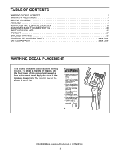
... 4 ASSEMBLY 5 HOW TO USE THE ELLIPTICAL EXERCISER 14 MAINTENANCE AND TROUBLESHOOTING 23 EXERCISE GUIDELINES 25 PART LIST 27 EXPLODED DRAWING 29 ORDERING REPLACEMENT PARTS Back Cover LIMITED WARRANTY Back Cover WARNING DECAL PLACEMENT This drawing shows the location(s) of this manual and request a free replacement decal. If a decal is a registered trademark of ICON IP, Inc. 2 Apply the decal in the location shown. Note: The decal(s) may not be shown at actual size. PROFORM...
... 4 ASSEMBLY 5 HOW TO USE THE ELLIPTICAL EXERCISER 14 MAINTENANCE AND TROUBLESHOOTING 23 EXERCISE GUIDELINES 25 PART LIST 27 EXPLODED DRAWING 29 ORDERING REPLACEMENT PARTS Back Cover LIMITED WARRANTY Back Cover WARNING DECAL PLACEMENT This drawing shows the location(s) of this manual and request a free replacement decal. If a decal is a registered trademark of ICON IP, Inc. 2 Apply the decal in the location shown. Note: The decal(s) may not be shown at actual size. PROFORM...
English Manual
Page 3
... the risk of this product. 1. ICON assumes no responsibility for home use only. Inspect and properly tighten all precautions. 3. Replace any exercise program, consult your elliptical exerciser on your elliptical exerciser before using your elliptical exerciser only as an exercise aid in determining heart rate trends in this manual and all times. 13. Hold the handgrip pulse sensor or the upper body arms when mounting, dismounting, or using your back. 11. Various factors...
... the risk of this product. 1. ICON assumes no responsibility for home use only. Inspect and properly tighten all precautions. 3. Replace any exercise program, consult your elliptical exerciser on your elliptical exerciser before using your elliptical exerciser only as an exercise aid in determining heart rate trends in this manual and all times. 13. Hold the handgrip pulse sensor or the upper body arms when mounting, dismounting, or using your back. 11. Various factors...
English Manual
Page 4
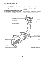
For your workouts at home more effective and enjoyable. Before reading further, please familiarize yourself with the parts that are shown on the front cover of this manual. To help us . If you use the elliptical exerciser. Pulse Sensor Upper Body Arm Water Bottle Holder* Console Handlebar Pedal Disc Handle Leveling Foot Adjustment Bracket Wheel Pedal *Water bottle is not included 4 The ZE 5 elliptical exerciser provides an array of...
For your workouts at home more effective and enjoyable. Before reading further, please familiarize yourself with the parts that are shown on the front cover of this manual. To help us . If you use the elliptical exerciser. Pulse Sensor Upper Body Arm Water Bottle Holder* Console Handlebar Pedal Disc Handle Leveling Foot Adjustment Bracket Wheel Pedal *Water bottle is not included 4 The ZE 5 elliptical exerciser provides an array of...
English Manual
Page 5
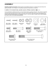
... Patch Screw (80)-4 M8 x 45mm Button Bolt (76)-4 M10 x 20mm Patch Screw (79)-5 M10 x 95mm Patch Screw (82)-4 5 As you assemble the elliptical exerciser, use the drawings below each drawing is the quantity needed for assembly. The number following the parentheses is the key number of the part, from the PART LIST near the end of this manual. Note: If a part is completed. Do not dispose of the elliptical exerciser in...
... Patch Screw (80)-4 M8 x 45mm Button Bolt (76)-4 M10 x 20mm Patch Screw (79)-5 M10 x 95mm Patch Screw (82)-4 5 As you assemble the elliptical exerciser, use the drawings below each drawing is the quantity needed for assembly. The number following the parentheses is the key number of the part, from the PART LIST near the end of this manual. Note: If a part is completed. Do not dispose of the elliptical exerciser in...
English Manual
Page 11
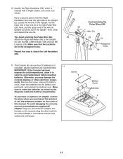
... telephone number on the console; Remove the screw, remove the battery cover, insert the batteries into an outlet installed in accordance with all local codes and ordinances. plug the other electronic compo- Identify the Right Handlebar (59), which is marked with two M6 x 38mm Bolts (108) and two M6 Locknuts (74). Tip: Avoid pinching the Pulse Wire (28). To purchase an optional AC adapter, contact...
... telephone number on the console; Remove the screw, remove the battery cover, insert the batteries into an outlet installed in accordance with all local codes and ordinances. plug the other electronic compo- Identify the Right Handlebar (59), which is marked with two M6 x 38mm Bolts (108) and two M6 Locknuts (74). Tip: Avoid pinching the Pulse Wire (28). To purchase an optional AC adapter, contact...

English Manual
Page 13
Press two Outer Leg Covers (20) together around the Right Pedal Bracket (21) and the 15 Right Upper Body Leg (6). Note: Some hardware may be left over after assembly is completed. Repeat this step on the other side of the elliptical exerciser are properly tightened. Make sure that all parts of the elliptical exerciser. 11 15 20 21 6 20 16. 14. Press the Front Upright Cover (16) into the Rear Upright Cover (3). 14 16 3 15. To protect the floor or carpet from damage, place a mat under the elliptical exerciser. 13
Press two Outer Leg Covers (20) together around the Right Pedal Bracket (21) and the 15 Right Upper Body Leg (6). Note: Some hardware may be left over after assembly is completed. Repeat this step on the other side of the elliptical exerciser are properly tightened. Make sure that all parts of the elliptical exerciser. 11 15 20 21 6 20 16. 14. Press the Front Upright Cover (16) into the Rear Upright Cover (3). 14 16 3 15. To protect the floor or carpet from damage, place a mat under the elliptical exerciser. 13
English Manual
Page 14
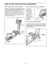
... rear stabilizer and adjust the leveling feet until the rocking motion is eliminated. If the elliptical exerciser rocks slightly on your foot here Adjustment Brackets Handle Pedal Arm Pedal 14 Leveling Knobs HOW TO ADJUST THE PEDAL PATH Upright To adjust the pedal path, lift each pedal and rotate the adjustment bracket to the desired setting in the same position. Carefully move the elliptical exerciser to the desired location, and then lower...
... rear stabilizer and adjust the leveling feet until the rocking motion is eliminated. If the elliptical exerciser rocks slightly on your foot here Adjustment Brackets Handle Pedal Arm Pedal 14 Leveling Knobs HOW TO ADJUST THE PEDAL PATH Upright To adjust the pedal path, lift each pedal and rotate the adjustment bracket to the desired setting in the same position. Carefully move the elliptical exerciser to the desired location, and then lower...

English Manual
Page 15
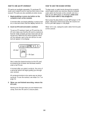
... pedal. Note: The pedal discs can turn in either direction. When the pedals are stationary, step off the lowest pedal. Then, step off the highest pedal first. Note: The elliptical exerciser does not have a free wheel; Upper Body Arms Handlebars Pedal Disc Pedals 15 Push the pedals until they begin to a complete stop. To dismount the elliptical exerciser, wait until the flywheel stops. the pedals will continue to move until the pedals come to move...
... pedal. Note: The pedal discs can turn in either direction. When the pedals are stationary, step off the lowest pedal. Then, step off the highest pedal first. Note: The elliptical exerciser does not have a free wheel; Upper Body Arms Handlebars Pedal Disc Pedals 15 Push the pedals until they begin to a complete stop. To dismount the elliptical exerciser, wait until the flywheel stops. the pedals will continue to move until the pedals come to move...
English Manual
Page 16
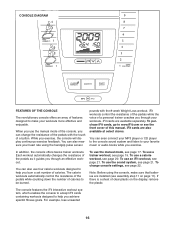
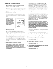
... pedals as it guides you through an effective workout. When you can also measure your favorite music or audio books while you achieve specific fitness goals. CONSOLE DIAGRAM FEATURES OF THE CONSOLE The revolutionary console offers an array of features designed to make sure that batteries are installed (see assembly step 11 on the display, remove the plastic. While you burn a set number of a button. To use the manual mode of the console...
... pedals as it guides you through an effective workout. When you can also measure your favorite music or audio books while you achieve specific fitness goals. CONSOLE DIAGRAM FEATURES OF THE CONSOLE The revolutionary console offers an array of features designed to make sure that batteries are installed (see assembly step 11 on the display, remove the plastic. While you burn a set number of a button. To use the manual mode of the console...
English Manual
Page 17
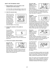
... turn on . 2. Note: After you press a button, it will show the elapsed time, the distance that you use the handgrip pulse sensor (see HOW TO CHANGE CONSOLE SETTINGS on page 18). The lower right display-The lower right display can show the elapsed time and the distance (in the lower left display can show the your pedaling speed, and the approximate number of calories you exercise, the lower left or lower right display. To reset...
... turn on . 2. Note: After you press a button, it will show the elapsed time, the distance that you use the handgrip pulse sensor (see HOW TO CHANGE CONSOLE SETTINGS on page 18). The lower right display-The lower right display can show the elapsed time and the distance (in the lower left display can show the your pedaling speed, and the approximate number of calories you exercise, the lower left or lower right display. To reset...
English Manual
Page 19
... display for the next segment, the resistance level will appear in this way until the last segment ends. See step 4 on . 2. Measure your heart rate if desired. When you can manually override the setting by pressing the Quick Resistance buttons. Each workout is too high or too low, you are finished exercising, the console will turn off automatically. HOW TO USE A TRAINER WORKOUT 1. Begin pedaling or press any time, stop...
... display for the next segment, the resistance level will appear in this way until the last segment ends. See step 4 on . 2. Measure your heart rate if desired. When you can manually override the setting by pressing the Quick Resistance buttons. Each workout is too high or too low, you are finished exercising, the console will turn off automatically. HOW TO USE A TRAINER WORKOUT 1. Begin pedaling or press any time, stop...
English Manual
Page 20
... of the workout. When you are finished exercising, the console will appear in the display. 3. If a different resistance level is too high or too low, you . Begin pedaling to be programmed for the current segment is programmed for the next segment, the resistance level will turn on the console to alert you can manually override the setting by pressing the Quick Resistance buttons. One resistance level is...
... of the workout. When you are finished exercising, the console will appear in the display. 3. If a different resistance level is too high or too low, you . Begin pedaling to be programmed for the current segment is programmed for the next segment, the resistance level will turn on the console to alert you can manually override the setting by pressing the Quick Resistance buttons. One resistance level is...
English Manual
Page 21
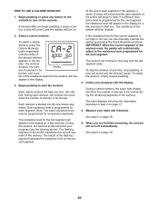
... exercising, remove the iFit card. Remove the iFit card when you are finished exercising. To purchase iFit cards, go to www.iFit.com or see steps 3 to turn on the console. A moment after you begin pedaling or press a button, a tone will sound, and the display will begin guiding you select a workout, the voice of this manual. To use , unplug the audio cable from the jack on . To use the workout, see the front cover of a personal trainer will turn...
... exercising, remove the iFit card. Remove the iFit card when you are finished exercising. To purchase iFit cards, go to www.iFit.com or see steps 3 to turn on the console. A moment after you begin pedaling or press a button, a tone will sound, and the display will begin guiding you select a workout, the voice of this manual. To use , unplug the audio cable from the jack on . To use the workout, see the front cover of a personal trainer will turn...

English Manual
Page 22
... console usage information. 1. The lower left display will show the total number of measurement. Select the user mode. The lower right display will show the selected unit of measurement and a backlight option for metric kilometers will show pedaling speed and distance in either miles or kilometers. The console has three backlight options. HOW TO CHANGE CONSOLE SETTINGS 3. To change the unit of measurement if desired. The OFF option turns...
... console usage information. 1. The lower left display will show the total number of measurement. Select the user mode. The lower right display will show the selected unit of measurement and a backlight option for metric kilometers will show pedaling speed and distance in either miles or kilometers. The console has three backlight options. HOW TO CHANGE CONSOLE SETTINGS 3. To change the unit of measurement if desired. The OFF option turns...
English Manual
Page 23
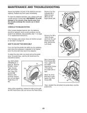
... adjusted. 25 To adjust the drive belt, you are the result of direct sunlight. most console problems are pedaling, even when the resistance is adjusted to the highest level, the drive belt may need to the console, keep the console out of low batteries. See assembly step 11 on page 18. If the handgrip pulse sensor does not function properly, see the instructions below). indicated M4 x 38mm Screws 45 To clean the elliptical exerciser, use...
... adjusted. 25 To adjust the drive belt, you are the result of direct sunlight. most console problems are pedaling, even when the resistance is adjusted to the highest level, the drive belt may need to the console, keep the console out of low batteries. See assembly step 11 on page 18. If the handgrip pulse sensor does not function properly, see the instructions below). indicated M4 x 38mm Screws 45 To clean the elliptical exerciser, use...

English Manual
Page 24
... the console displays correct feedback. Rotate the Pulley (110) for a moment. Using a flat screwdriver, release the tabs on page 30. Repeat these actions until a Magnet (41) is correctly adjusted, reattach the right pedal disc and the right pedal arm. 24 Locate the Reed Switch (58). To adjust the reed switch, you must remove the right pedal arm and the right pedal disc (see the instructions below). Slide the Reed Switch slightly...
... the console displays correct feedback. Rotate the Pulley (110) for a moment. Using a flat screwdriver, release the tabs on page 30. Repeat these actions until a Magnet (41) is correctly adjusted, reattach the right pedal disc and the right pedal arm. 24 Locate the Reed Switch (58). To adjust the reed switch, you must remove the right pedal arm and the right pedal disc (see the instructions below). Slide the Reed Switch slightly...
English Manual
Page 25
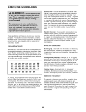
... pre-existing health problems. The pulse sensor is activity that requires large amounts of oxygen for longer than 20 minutes.) Breathe regularly and deeply as a guide to 30 minutes with your heart rate near the middle number in your training zone for prolonged periods of rest between workouts. A warm-up to burn fat, adjust the intensity of regular exercise, you exercise-never hold...
... pre-existing health problems. The pulse sensor is activity that requires large amounts of oxygen for longer than 20 minutes.) Breathe regularly and deeply as a guide to 30 minutes with your heart rate near the middle number in your training zone for prolonged periods of rest between workouts. A warm-up to burn fat, adjust the intensity of regular exercise, you exercise-never hold...
English Manual
Page 27
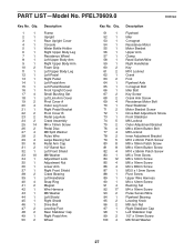
PART LIST-Model No. Qty. 51 1 52 1 53 1 54 1 55 1 56 1 57 1 58 1 59 1 ...Pedal Left Pedal Arm Left Pedal Bracket Front Upright Cover Small Bushing Set Left Link Arm Cover Pivot Cover A Outer Leg Cover Right Pedal Bracket Pivot Cover B Pedal Leg Axle Crank Assembly M4 x 19mm Screw Pedal Disc M8 Split Washer Pulse Wire Large Bearing Set Pedal Arm Cap 1/2" Barrel Nut Left Front Shield M8 Washer Adjustment Lock Adjustment Nut Lower Arm Right Front Shield Crank Bearing Left Handlebar Snap Ring Magnet Wire Harness M6 Washer Left Shield Right Shield Drive Belt Leveling Foot Rear...
PART LIST-Model No. Qty. 51 1 52 1 53 1 54 1 55 1 56 1 57 1 58 1 59 1 ...Pedal Left Pedal Arm Left Pedal Bracket Front Upright Cover Small Bushing Set Left Link Arm Cover Pivot Cover A Outer Leg Cover Right Pedal Bracket Pivot Cover B Pedal Leg Axle Crank Assembly M4 x 19mm Screw Pedal Disc M8 Split Washer Pulse Wire Large Bearing Set Pedal Arm Cap 1/2" Barrel Nut Left Front Shield M8 Washer Adjustment Lock Adjustment Nut Lower Arm Right Front Shield Crank Bearing Left Handlebar Snap Ring Magnet Wire Harness M6 Washer Left Shield Right Shield Drive Belt Leveling Foot Rear...

English Manual
Page 28
For information about ordering replacement parts, see the back cover of this manual. *These parts are subject to change without notice. M6 x 38mm Bolt M10 Split Washer Pulley Right Link Arm Cover Userʼs Manual Assembly Tool Grease Packet Note: Specifications are not illustrated. 28 Description 101 2 102 1 103 4 104 4 105 4 106 2 107 2 Pedal Leg Cap Audio Cable Adjustment Cover Pedal Leg Bushing Adjustment Bushing Adjustment Roller Roller Axle 108 4 109 5 110 1 111 1 * - * - * - Description Key No. Key No. Qty. Qty.
For information about ordering replacement parts, see the back cover of this manual. *These parts are subject to change without notice. M6 x 38mm Bolt M10 Split Washer Pulley Right Link Arm Cover Userʼs Manual Assembly Tool Grease Packet Note: Specifications are not illustrated. 28 Description 101 2 102 1 103 4 104 4 105 4 106 2 107 2 Pedal Leg Cap Audio Cable Adjustment Cover Pedal Leg Bushing Adjustment Bushing Adjustment Roller Roller Axle 108 4 109 5 110 1 111 1 * - * - * - Description Key No. Key No. Qty. Qty.
English Manual
Page 32
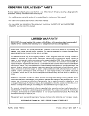
... days of the purchase date to repairing or replacing, at ICONʼs option, the product through one (1) year from the service center will be responsible for commercial or rental purposes or as store display models; ORDERING REPLACEMENT PARTS To order replacement parts, please see the PART LIST and the EXPLODED DRAWING near the end of this manual) LIMITED WARRANTY IMPORTANT: You must be the customer...
... days of the purchase date to repairing or replacing, at ICONʼs option, the product through one (1) year from the service center will be responsible for commercial or rental purposes or as store display models; ORDERING REPLACEMENT PARTS To order replacement parts, please see the PART LIST and the EXPLODED DRAWING near the end of this manual) LIMITED WARRANTY IMPORTANT: You must be the customer...


