
English Manual
Page 1
please contact Customer Care. USERʼS MANUAL www.proform.com Model No. MT Sat. 8 a.m.-4 p.m. Serial Number Decal (under frame) QUESTIONS? Keep this manual) before using this equipment. IMPORTANT: Please register this product (see the ...
please contact Customer Care. USERʼS MANUAL www.proform.com Model No. MT Sat. 8 a.m.-4 p.m. Serial Number Decal (under frame) QUESTIONS? Keep this manual) before using this equipment. IMPORTANT: Please register this product (see the ...
English Manual
Page 2
PROFORM is missing or illegible, see the front cover of this manual and request a free replacement decal. If a decal is a registered trademark of the warning decal(s). TABLE OF CONTENTS WARNING DECAL PLACEMENT 2 IMPORTANT PRECAUTIONS 3 BEFORE YOU BEGIN 4 ASSEMBLY 5 HOW TO USE THE ELLIPTICAL EXERCISER 14 MAINTENANCE AND TROUBLESHOOTING 23 EXERCISE GUIDELINES 25 PART...
PROFORM is missing or illegible, see the front cover of this manual and request a free replacement decal. If a decal is a registered trademark of the warning decal(s). TABLE OF CONTENTS WARNING DECAL PLACEMENT 2 IMPORTANT PRECAUTIONS 3 BEFORE YOU BEGIN 4 ASSEMBLY 5 HOW TO USE THE ELLIPTICAL EXERCISER 14 MAINTENANCE AND TROUBLESHOOTING 23 EXERCISE GUIDELINES 25 PART...
English Manual
Page 3
... sensor or the upper body arms when mounting, dismounting, or using your physician. The pulse sensor is at all warnings on your elliptical exerciser in general. 12. Inspect and properly tighten all important precautions and instructions in serious injury or death. Always wear athletic shoes... determining heart rate trends in a commercial, rental, or institutional setting. 4. The pulse sensor is the responsibility of this manual. 3 Your elliptical exerciser should not be used by or through the use of the owner to protect the floor or carpet. Do not use only. do...
... sensor or the upper body arms when mounting, dismounting, or using your physician. The pulse sensor is at all warnings on your elliptical exerciser in general. 12. Inspect and properly tighten all important precautions and instructions in serious injury or death. Always wear athletic shoes... determining heart rate trends in a commercial, rental, or institutional setting. 4. The pulse sensor is the responsibility of this manual. 3 Your elliptical exerciser should not be used by or through the use of the owner to protect the floor or carpet. Do not use only. do...
English Manual
Page 4
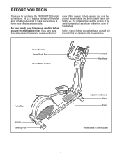
... Handle Leveling Foot Adjustment Bracket Wheel Pedal *Water bottle is not included 4 To help us . The ZE 5 elliptical exerciser provides an array of features designed to make your benefit, read this manual carefully before you , note the ...product model number and serial number before contacting us assist you use the elliptical exerciser. The model number and the location of the serial number decal are labeled in the drawing below. ...please see the front cover of this manual. If you for purchasing the PROFORM® ZE 5 elliptical exerciser.
... Handle Leveling Foot Adjustment Bracket Wheel Pedal *Water bottle is not included 4 To help us . The ZE 5 elliptical exerciser provides an array of features designed to make your benefit, read this manual carefully before you , note the ...product model number and serial number before contacting us assist you use the elliptical exerciser. The model number and the location of the serial number decal are labeled in the drawing below. ...please see the front cover of this manual. If you for purchasing the PROFORM® ZE 5 elliptical exerciser.
English Manual
Page 5
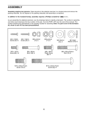
...: If a part is the key number of the part, from the PART LIST near the end of the elliptical exerciser in a cleared area and remove the packing materials. As you assemble the elliptical exerciser, use the drawings below each drawing is not in parentheses below to see if it has been preassembled...
...: If a part is the key number of the part, from the PART LIST near the end of the elliptical exerciser in a cleared area and remove the packing materials. As you assemble the elliptical exerciser, use the drawings below each drawing is not in parentheses below to see if it has been preassembled...

English Manual
Page 6
To make assembly easier, read the 1 information on page 5 before you begin. Orient the Front Stabilizer (73) so that the Wheels (50) are oriented as shown. 2 While a second person lifts the front of the Frame (1), attach the Rear Stabilizer (70) to the Frame with two M10 x 95mm Patch Screws (82). 82 2. 1. While a second person lifts the rear of the Frame (1), attach the Front Stabilizer (73) to the Frame with two M10 x 95mm Patch Screws (82). 1 70 50 73 1 82 50 6
To make assembly easier, read the 1 information on page 5 before you begin. Orient the Front Stabilizer (73) so that the Wheels (50) are oriented as shown. 2 While a second person lifts the front of the Frame (1), attach the Rear Stabilizer (70) to the Frame with two M10 x 95mm Patch Screws (82). 82 2. 1. While a second person lifts the rear of the Frame (1), attach the Front Stabilizer (73) to the Frame with two M10 x 95mm Patch Screws (82). 1 70 50 73 1 82 50 6

English Manual
Page 7
Do not tighten the Patch Screws yet. Avoid pinching the wires 109 79 2 1 89 42 109 79 7 Tip: Avoid pinching the wires. 3. Attach the Upright (2) to the Wire Harness (42). Insert the Upright (2) into the Frame (1). Orient the Upright (2) as shown. 3 While a second person holds the Upright (2) near the Frame (1), connect the Upper Wire Harness (89) to the Frame (1) with five M10 x 20mm Patch Screws (79) and five M10 Split Washers (109).
Do not tighten the Patch Screws yet. Avoid pinching the wires 109 79 2 1 89 42 109 79 7 Tip: Avoid pinching the wires. 3. Attach the Upright (2) to the Wire Harness (42). Insert the Upright (2) into the Frame (1). Orient the Upright (2) as shown. 3 While a second person holds the Upright (2) near the Frame (1), connect the Upper Wire Harness (89) to the Frame (1) with five M10 x 20mm Patch Screws (79) and five M10 Split Washers (109).

English Manual
Page 8
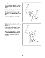
Orient the Right Pedal (13), the Right Pedal Bracket (21), and the Right Upper Body Leg (6) as shown. Attach the Right Pedal (13) to the axle on the Right Upper Body Leg (6). 5 Slide the front end of the included grease to the Right Pedal Bracket (21) with a "Right" sticker. Apply some of the Right Pedal Arm (49) onto the axle on the Right Upper Body Leg (6). Identify the Right Pedal Bracket (21) and the Right Upper Body Leg (6) assembly, which is 4 marked with six M6 x 12mm Screws (84). 13 Repeat this step to attach the Left Pedal Arm (not shown) to the Left Upper Body Leg (...
Orient the Right Pedal (13), the Right Pedal Bracket (21), and the Right Upper Body Leg (6) as shown. Attach the Right Pedal (13) to the axle on the Right Upper Body Leg (6). 5 Slide the front end of the included grease to the Right Pedal Bracket (21) with a "Right" sticker. Apply some of the Right Pedal Arm (49) onto the axle on the Right Upper Body Leg (6). Identify the Right Pedal Bracket (21) and the Right Upper Body Leg (6) assembly, which is 4 marked with six M6 x 12mm Screws (84). 13 Repeat this step to attach the Left Pedal Arm (not shown) to the Left Upper Body Leg (...
English Manual
Page 9
Slide the Right Upper Body Arm (9) onto the right side of a second person, slide the Right Upper Body Leg (6) onto the Right Upper 7 Body Arm (9). Attach the Left Upper Body Leg (11) to the Left Upper Body Arm (8) in the hexagonal holes. Repeat this step to the axle on the right side of the Upright (2). 6 Identify the Right Upper Body Arm (9), which is marked with a "Right" sticker, and orient it as shown. Grease 9 2 33 80 7. See step 6. With the help of the Upright (2). Do not tighten the Patch Screw 8 yet. Attach the Right Upper Body Leg (6) with an M8 x ...
Slide the Right Upper Body Arm (9) onto the right side of a second person, slide the Right Upper Body Leg (6) onto the Right Upper 7 Body Arm (9). Attach the Left Upper Body Leg (11) to the Left Upper Body Arm (8) in the hexagonal holes. Repeat this step to the axle on the right side of the Upright (2). 6 Identify the Right Upper Body Arm (9), which is marked with a "Right" sticker, and orient it as shown. Grease 9 2 33 80 7. See step 6. With the help of the Upright (2). Do not tighten the Patch Screw 8 yet. Attach the Right Upper Body Leg (6) with an M8 x ...

English Manual
Page 10
... Patch Screws. 25 2 Tip: Avoid pinching the wires. Tip: Tighten the two rear Patch 32 Screws first and then tighten the other side of the elliptical exerciser. Identify a Pivot Cover A (19), which has hooks, and a Pivot Cover B (22), which are positioned as shown. 9 8 19 22 Tabs 19 22 Hooks 19 Hooks...
... Patch Screws. 25 2 Tip: Avoid pinching the wires. Tip: Tighten the two rear Patch 32 Screws first and then tighten the other side of the elliptical exerciser. Identify a Pivot Cover A (19), which has hooks, and a Pivot Cover B (22), which are positioned as shown. 9 8 19 22 Tabs 19 22 Hooks 19 Hooks...
English Manual
Page 11
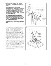
Make sure that the Locknuts are recommended. 11 IMPORTANT: If the Console has been exposed to cold temperatures, allow it as shown by the diagrams inside the battery compartments. Repeat this manual. Otherwise, you purchased this product or call the telephone number on the console; To avoid damaging the console, use four D batteries (not included); Tie the lower end of this step to the right Pulse Wire (28). Then, untie and discard the wire tie. alkaline batteries are in the Upright. Plug one end of the AC adapter into the jack on the cover of the wire tie to attach...
Make sure that the Locknuts are recommended. 11 IMPORTANT: If the Console has been exposed to cold temperatures, allow it as shown by the diagrams inside the battery compartments. Repeat this manual. Otherwise, you purchased this product or call the telephone number on the console; To avoid damaging the console, use four D batteries (not included); Tie the lower end of this step to the right Pulse Wire (28). Then, untie and discard the wire tie. alkaline batteries are in the Upright. Plug one end of the AC adapter into the jack on the cover of the wire tie to attach...

English Manual
Page 12
While a second person holds the Console (4) near the Upright (2), connect the console wires 12 to the Upper Wire Harness (89) and to the Upright (2) with four M4 x 16mm Screws (92). 4 Avoid pinching the wires Console Wires 28 2 92 89 92 13. Insert the excess wires into the Upright (2) or into the Console (4). Attach the Console (4) to the Upright (2) with two M4 x 16mm Screws (92). 13 92 2 3 12 Attach the Rear Upright Cover (3) to the Pulse Wires (28). 12. Tip: Avoid pinching the wires.
While a second person holds the Console (4) near the Upright (2), connect the console wires 12 to the Upper Wire Harness (89) and to the Upright (2) with four M4 x 16mm Screws (92). 4 Avoid pinching the wires Console Wires 28 2 92 89 92 13. Insert the excess wires into the Upright (2) or into the Console (4). Attach the Console (4) to the Upright (2) with two M4 x 16mm Screws (92). 13 92 2 3 12 Attach the Rear Upright Cover (3) to the Pulse Wires (28). 12. Tip: Avoid pinching the wires.

English Manual
Page 13
14. Repeat this step on the other side of the elliptical exerciser are properly tightened. Note: Some hardware may be left over after assembly is completed. Make sure that all parts of the elliptical exerciser. 11 15 20 21 6 20 16. To protect the floor or carpet from damage, place a mat under the elliptical exerciser. 13 Press the Front Upright Cover (16) into the Rear Upright Cover (3). 14 16 3 15. Press two Outer Leg Covers (20) together around the Right Pedal Bracket (21) and the 15 Right Upper Body Leg (6).
14. Repeat this step on the other side of the elliptical exerciser are properly tightened. Note: Some hardware may be left over after assembly is completed. Make sure that all parts of the elliptical exerciser. 11 15 20 21 6 20 16. To protect the floor or carpet from damage, place a mat under the elliptical exerciser. 13 Press the Front Upright Cover (16) into the Rear Upright Cover (3). 14 16 3 15. Press two Outer Leg Covers (20) together around the Right Pedal Bracket (21) and the 15 Right Upper Body Leg (6).
English Manual
Page 14
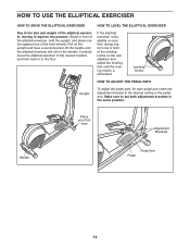
...and place one foot against one or both adjustment brackets in the same position. HOW TO USE THE ELLIPTICAL EXERCISER HOW TO MOVE THE ELLIPTICAL EXERCISER HOW TO LEVEL THE ELLIPTICAL EXERCISER Due to the size and weight of the leveling knobs on the rear stabilizer and adjust the leveling...on the upright and have a second person lift the handle until the rocking motion is eliminated. If the elliptical exerciser rocks slightly on the wheels. Carefully move the elliptical exerciser to the desired location, and then lower it requires two persons. Leveling Knobs HOW TO ADJUST THE PEDAL...
...and place one foot against one or both adjustment brackets in the same position. HOW TO USE THE ELLIPTICAL EXERCISER HOW TO MOVE THE ELLIPTICAL EXERCISER HOW TO LEVEL THE ELLIPTICAL EXERCISER Due to the size and weight of the leveling knobs on the rear stabilizer and adjust the leveling...on the upright and have a second person lift the handle until the rocking motion is eliminated. If the elliptical exerciser rocks slightly on the wheels. Carefully move the elliptical exerciser to the desired location, and then lower it requires two persons. Leveling Knobs HOW TO ADJUST THE PEDAL...

English Manual
Page 15
..., wait until the flywheel stops. When the pedals are stationary, step off the lowest pedal. HOW TO EXERCISE ON THE ELLIPTICAL EXERCISER To mount the elliptical exerciser, hold the handlebars or the upper body arms and step onto the pedal that is recommended that you can turn the pedal ... onto the other pedal. Note: The pedal discs can turn in either direction. Push the pedals until they begin to a complete stop. Note: The elliptical exerciser does not have a free wheel; however, for variety, you move with a continuous motion. It is in the direction shown by the arrow;
..., wait until the flywheel stops. When the pedals are stationary, step off the lowest pedal. HOW TO EXERCISE ON THE ELLIPTICAL EXERCISER To mount the elliptical exerciser, hold the handlebars or the upper body arms and step onto the pedal that is recommended that you can turn the pedal ... onto the other pedal. Note: The pedal discs can turn in either direction. Push the pedals until they begin to a complete stop. Note: The elliptical exerciser does not have a free wheel; however, for variety, you move with a continuous motion. It is in the direction shown by the arrow;
English Manual
Page 16
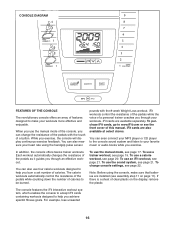
You can change console settings, see the front cover of this manual. iFit cards are available separately. You can even connect your MP3 player or CD player to the console sound system and listen to your workouts. To use the manual mode, see page 17. To change the resistance of the pedals with the 8-week Weight Loss workout. While you burn a set number of calories. iFit cards are also available at select stores. To purchase iFit cards, go to www.iFit.com or see page 22. The calorie workouts automatically control the resistance of the pedals while counting down ...
You can change console settings, see the front cover of this manual. iFit cards are available separately. You can even connect your MP3 player or CD player to the console sound system and listen to your workouts. To use the manual mode, see page 17. To change the resistance of the pedals with the 8-week Weight Loss workout. While you burn a set number of calories. iFit cards are also available at select stores. To purchase iFit cards, go to www.iFit.com or see page 22. The calorie workouts automatically control the resistance of the pedals while counting down ...
English Manual
Page 17
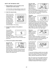
..., the display will not be selected. To reset the trip distance to reach the selected resistance level. 4. To view the total distance pedaled since the elliptical exerciser was purchased, press the Odometer button a second time. To view or change the resistance of the pedals by pressing any button on the console...
..., the display will not be selected. To reset the trip distance to reach the selected resistance level. 4. To view the total distance pedaled since the elliptical exerciser was purchased, press the Odometer button a second time. To view or change the resistance of the pedals by pressing any button on the console...

English Manual
Page 18
Note: If you are sheets of clear plastic on the hand- never use alcohol, abrasives, or chemicals to move for several seconds, a tone will sound and the console will be reset. 18 If there are finished exercising, the console will turn off automatically. Contacts tacts on the metal con- For the most accurate heart rate reading, hold the handgrip pulse sensor with your palms resting against the metal contacts. If the pedals do not move your heart rate for at least 15 seconds. grip pulse sensor, remove the plas- When you continue to hold...
Note: If you are sheets of clear plastic on the hand- never use alcohol, abrasives, or chemicals to move for several seconds, a tone will sound and the console will be reset. 18 If there are finished exercising, the console will turn off automatically. Contacts tacts on the metal con- For the most accurate heart rate reading, hold the handgrip pulse sensor with your palms resting against the metal contacts. If the pedals do not move your heart rate for at least 15 seconds. grip pulse sensor, remove the plas- When you continue to hold...
English Manual
Page 19
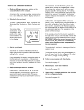
The flashing segment of the profile represents the current segment of the pedals will sound and the next segment of the flashing segment indicates the resistance level for consecutive segments. Set the pedal path. If you selected a Climb workout, move the pedals to the Ski setting. Follow your heart rate if desired. Measure your progress with the display. To select a trainer workout, press the desired Ski Workouts, Hike Workouts, or Climb Workouts button. At the end of each segment. If the resistance level for the current segment is programmed for a few seconds to start...
The flashing segment of the profile represents the current segment of the pedals will sound and the next segment of the flashing segment indicates the resistance level for consecutive segments. Set the pedal path. If you selected a Climb workout, move the pedals to the Ski setting. Follow your heart rate if desired. Measure your progress with the display. To select a trainer workout, press the desired Ski Workouts, Hike Workouts, or Climb Workouts button. At the end of each segment. If the resistance level for the current segment is programmed for a few seconds to start...
English Manual
Page 20
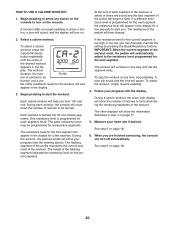
If a different resistance level is programmed for the next segment. Select a calorie workout. Each workout is too high or too low, you can manually override the setting by pressing the Quick Resistance buttons. During the workout, the workout profile will show the number of the flashing segment indicates the resistance level for a few seconds to be programmed for the current segment is divided into 30 one-minute segments. The height of calories to alert you begin to be burned. During a calorie workout, the lower right display will show the information described in ...
If a different resistance level is programmed for the next segment. Select a calorie workout. Each workout is too high or too low, you can manually override the setting by pressing the Quick Resistance buttons. During the workout, the workout profile will show the number of the flashing segment indicates the resistance level for a few seconds to be programmed for the current segment is divided into 30 one-minute segments. The height of calories to alert you begin to be burned. During a calorie workout, the lower right display will show the information described in ...