Installation Manual
Page 1
AUDIO/VIDEO MULTI-CHANNEL RECEIVER VSX-D814 VSX-D914 Operating Instructions
AUDIO/VIDEO MULTI-CHANNEL RECEIVER VSX-D814 VSX-D914 Operating Instructions
Installation Manual
Page 2
...LES LAMES PEUVENT ETRE INSEREES A FOND SANS EN LAISSER AUCUNE PARTIE A DECOUVVERT. D1-4-2-1_En WARNING: Handling the cord on this Pioneer product. Wash hands after handling D36-P4_En IMPORTANT NOTICE - For U.S. After you will know how to operate your model properly. ...reasonable protection against harmful interference in a safe place for connections. D2-4-4-1_EF WARNING - Increase the separation between the equipment and receiver. - THE SERIAL NUMBER FOR THIS EQUIPMENT IS LOCATED IN THE REAR. Please read through these operating instructions so you have ...
...LES LAMES PEUVENT ETRE INSEREES A FOND SANS EN LAISSER AUCUNE PARTIE A DECOUVVERT. D1-4-2-1_En WARNING: Handling the cord on this Pioneer product. Wash hands after handling D36-P4_En IMPORTANT NOTICE - For U.S. After you will know how to operate your model properly. ...reasonable protection against harmful interference in a safe place for connections. D2-4-4-1_EF WARNING - Increase the separation between the equipment and receiver. - THE SERIAL NUMBER FOR THIS EQUIPMENT IS LOCATED IN THE REAR. Please read through these operating instructions so you have ...

Installation Manual
Page 4
...A and B speaker systems 22 Hints on speaker placement 22 Connecting additional amplifiers 24 AC outlet 25 Operating other Pioneer components . . . . 25 Using this receiver with a Pioneer plasma display 26 05 Controls and displays Front panel 27 Display 29 Remote control 31 06 Listening to your system... Playing other sources 40 Selecting the multi-channel analog inputs 41 Using the sleep timer 41 07 Setting up the receiver Choosing your receiver setup 42 Speaker setting 43 Surround back speaker setting 44 Subwoofer setting 44 Crossover frequency setting 44 LFE attenuator setting...
...A and B speaker systems 22 Hints on speaker placement 22 Connecting additional amplifiers 24 AC outlet 25 Operating other Pioneer components . . . . 25 Using this receiver with a Pioneer plasma display 26 05 Controls and displays Front panel 27 Display 29 Remote control 31 06 Listening to your system... Playing other sources 40 Selecting the multi-channel analog inputs 41 Using the sleep timer 41 07 Setting up the receiver Choosing your receiver setup 42 Speaker setting 43 Surround back speaker setting 44 Subwoofer setting 44 Crossover frequency setting 44 LFE attenuator setting...
Installation Manual
Page 6
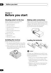
...this unit may have different voltages. 01 Before you start Chapter 1: Before you start Checking what's in the box Please check that you've received the following supplied accessories: • AM loop antenna • FM wire antenna • AA/LR6 dry cell batteries x2 • Remote ...control • These operating instructions • Warranty Card VSX-D914 model only: • Microphone • Microphone stand Making cable connections Make sure not to bend the cables over the top of this unit ...
...this unit may have different voltages. 01 Before you start Chapter 1: Before you start Checking what's in the box Please check that you've received the following supplied accessories: • AM loop antenna • FM wire antenna • AA/LR6 dry cell batteries x2 • Remote ...control • These operating instructions • Warranty Card VSX-D914 model only: • Microphone • Microphone stand Making cable connections Make sure not to bend the cables over the top of this unit ...
Installation Manual
Page 7
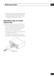
...range of used batteries, please comply with governmental regulations or environmental public instruction's rules that is emitting infrared rays. • The receiver is located near a device that apply in your country or area. Before you start 01 • When disposing of remote control... not work properly if: • There are obstacles between the remote control and the receiver's remote sensor. • Direct sunlight or fluorescent light is shining onto the remote sensor. • The receiver is operated simultaneously with another infrared remote control unit. 30 30 23ft (7m) 7 En...
...range of used batteries, please comply with governmental regulations or environmental public instruction's rules that is emitting infrared rays. • The receiver is located near a device that apply in your country or area. Before you start 01 • When disposing of remote control... not work properly if: • There are obstacles between the remote control and the receiver's remote sensor. • Direct sunlight or fluorescent light is shining onto the remote sensor. • The receiver is operated simultaneously with another infrared remote control unit. 30 30 23ft (7m) 7 En...
Installation Manual
Page 8
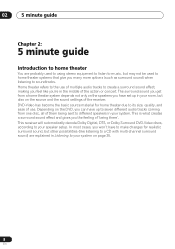
... disc, all of use. DVD-Video has become the basic source material for realistic surround sound, but other possibilities (like you the feeling of the receiver. This receiver will automatically decode Dolby Digital, DTS, or Dolby Surround DVD-Video discs, according to your speaker setup. 02 5 minute guide Chapter 2: 5 minute guide Introduction...
... disc, all of use. DVD-Video has become the basic source material for realistic surround sound, but other possibilities (like you the feeling of the receiver. This receiver will automatically decode Dolby Digital, DTS, or Dolby Surround DVD-Video discs, according to your speaker setup. 02 5 minute guide Chapter 2: 5 minute guide Introduction...
Installation Manual
Page 9
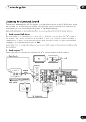
...IN / LD FRONT D V D 5.1CH REC INPUT CD-R IN /TAPE / MD SUB WOOFER PREOUT Video cord 9 En 5 minute guide 02 Listening to Surround Sound This receiver was designed with the easiest possible setup in mind, so with either a coaxial, or an optical connection (you don't need to connect both). For surround... with the following quick setup guide, you should refer to Digital input settings on your DVD player. Use a video cord to connect your receiver to the receiver. In most cases, you can do this unit to the AC power source. 1 Hook up using an optical cable, you hook up ...
...IN / LD FRONT D V D 5.1CH REC INPUT CD-R IN /TAPE / MD SUB WOOFER PREOUT Video cord 9 En 5 minute guide 02 Listening to Surround Sound This receiver was designed with the easiest possible setup in mind, so with either a coaxial, or an optical connection (you don't need to connect both). For surround... with the following quick setup guide, you should refer to Digital input settings on your DVD player. Use a video cord to connect your receiver to the receiver. In most cases, you can do this unit to the AC power source. 1 Hook up using an optical cable, you hook up ...
Installation Manual
Page 10
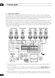
Also make sure the positive and negative (+/-) terminals on the receiver match those on the left to the left channel (-) terminal (shown below . In this unit to the audio input jack on this case the center ... speaker, connect the positive wire to the right channel (+) terminal, and the negative wire to the right terminal and the speaker on the speakers. The receiver will work with an impedance of eight speakers (including the subwoofer) is best. Make sure you plan to large. • To use speakers with just...
Also make sure the positive and negative (+/-) terminals on the receiver match those on the left to the left channel (-) terminal (shown below . In this unit to the audio input jack on this case the center ... speaker, connect the positive wire to the right channel (+) terminal, and the negative wire to the right terminal and the speaker on the speakers. The receiver will work with an impedance of eight speakers (including the subwoofer) is best. Make sure you plan to large. • To use speakers with just...

Installation Manual
Page 11
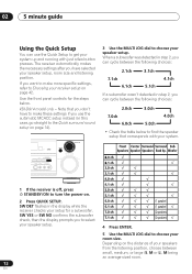
... get digital 2 channel stereo and analog sound. Use the MULTI JOG dial to select and ENTER to the left channel (-) terminal. VSX-D914 model only - See also Choosing your receiver setup on page 42 for more setup options. • Depending on the front panel to your system on page 35 for more... back speaker (or subwoofer) R SURROUND BACK L 4 Plug in the Quick surround sound setup on page 14. 6 Play a DVD, and adjust the volume to do this receiver. See Listening to specify your subwoofer and the TV. Check the manual that the DVD input is selected. For a more on , followed by your DVD...
... get digital 2 channel stereo and analog sound. Use the MULTI JOG dial to select and ENTER to the left channel (-) terminal. VSX-D914 model only - See also Choosing your receiver setup on page 42 for more setup options. • Depending on the front panel to your system on page 35 for more... back speaker (or subwoofer) R SURROUND BACK L 4 Plug in the Quick surround sound setup on page 14. 6 Play a DVD, and adjust the volume to do this receiver. See Listening to specify your subwoofer and the TV. Check the manual that the DVD input is selected. For a more on , followed by your DVD...
Installation Manual
Page 12
... straight to choose your speakers from the listening position, choose between small, medium, or large (S, M or L), M being an average-sized room. 12 En VSX-D914 model only - SW YES or SW NO confirms the subwoofer check, then the display prompts you have to make more specific settings, refer to... Choosing your system up and running with your system. 1 If the receiver is off, press STANDBY/ON to choose your speaker setup, room size and listening position. 02 5 minute guide Using the Quick Setup You can...
... straight to choose your speakers from the listening position, choose between small, medium, or large (S, M or L), M being an average-sized room. 12 En VSX-D914 model only - SW YES or SW NO confirms the subwoofer check, then the display prompts you have to make more specific settings, refer to... Choosing your system up and running with your system. 1 If the receiver is off, press STANDBY/ON to choose your speaker setup, room size and listening position. 02 5 minute guide Using the Quick Setup You can...
Installation Manual
Page 14
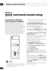
...in the room who will be startled by the noise. 6 Press MCACC SETUP. 03 Quick surround sound setup Chapter 3: Quick surround sound setup VSX-D914 model only Automatically calibrating your listening area (MCACC) The Multi-Channel Acoustic Calibration (MCACC) system measures the acoustic characteristics of your listening ...speakers are no one in the display for five seconds. DVD/LD TV/SAT DVR/VCR TVCONT MULTI CONTROL CD CD-R/TAPE TUNER RECEIVER 3 If the receiver is off, press STANDBY/ON to be loud, so take care that there is too high, NOISY! STATION TUNING ADVANCED STEREO/...
...in the room who will be startled by the noise. 6 Press MCACC SETUP. 03 Quick surround sound setup Chapter 3: Quick surround sound setup VSX-D914 model only Automatically calibrating your listening area (MCACC) The Multi-Channel Acoustic Calibration (MCACC) system measures the acoustic characteristics of your listening ...speakers are no one in the display for five seconds. DVD/LD TV/SAT DVR/VCR TVCONT MULTI CONTROL CD CD-R/TAPE TUNER RECEIVER 3 If the receiver is off, press STANDBY/ON to be loud, so take care that there is too high, NOISY! STATION TUNING ADVANCED STEREO/...

Installation Manual
Page 15
...with different size settings. When the auto surround setup is complete, the volume level returns to normal and COMPLETE, then RESUME shows in Choosing your receiver setup on page 42 to check other settings. • Depending on the characteristics of your room, sometimes identical speakers with cone sizes of the mic...6.1ch* 6.0ch 5.1ch* 5.0ch * Indicates a subwoofer is included in the display for five seconds. You can check the settings made with MCACC by using the receiver setup on page 42. 15 En If the subwoofer output level is too high/low, SW.VOL.DWN/SW.VOL.UP blinks in your speaker...
...with different size settings. When the auto surround setup is complete, the volume level returns to normal and COMPLETE, then RESUME shows in Choosing your receiver setup on page 42 to check other settings. • Depending on the characteristics of your room, sometimes identical speakers with cone sizes of the mic...6.1ch* 6.0ch 5.1ch* 5.0ch * Indicates a subwoofer is included in the display for five seconds. You can check the settings made with MCACC by using the receiver setup on page 42. 15 En If the subwoofer output level is too high/low, SW.VOL.DWN/SW.VOL.UP blinks in your speaker...
Installation Manual
Page 16
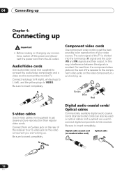
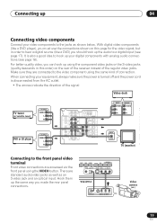
... source. Digital audio coaxial cord (or standard video cord) Optical cable 16 En Connect from an S-video jack on the rear of the receiver to an S-video jack on the video component you are hooking up • Before making or changing any connections, switch off the power ... is avoided. Y Green Blue P B P R Red S-video cables Use S-video cables (not supplied) to connect the monitor TV. The color signal of the receiver to the component video jacks on the video component you are used to connect digital components to get clearer picture reproduction than regular video cords.
... source. Digital audio coaxial cord (or standard video cord) Optical cable 16 En Connect from an S-video jack on the rear of the receiver to an S-video jack on the video component you are hooking up • Before making or changing any connections, switch off the power ... is avoided. Y Green Blue P B P R Red S-video cables Use S-video cables (not supplied) to connect the monitor TV. The color signal of the receiver to the component video jacks on the video component you are used to connect digital components to get clearer picture reproduction than regular video cords.
Installation Manual
Page 17
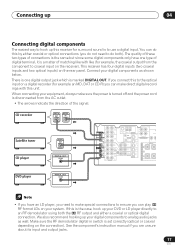
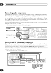
Connecting up 04 Connecting digital components The easiest way to hook up this receiver for surround sound is to an RF demodulator using both ). There is one type of digital terminal, it is marked DIGITAL OUT. If this is ... direction of matching like (for example an MD, DAT or CD-R) you connect this unit. If you can play 2 RF format LDs on the receiver). This receiver has four digital inputs (two coaxial inputs and two optical inputs) on the connection). You can do not need to make sure the power is...
Connecting up 04 Connecting digital components The easiest way to hook up this receiver for surround sound is to an RF demodulator using both ). There is one type of digital terminal, it is marked DIGITAL OUT. If this is ... direction of matching like (for example an MD, DAT or CD-R) you connect this unit. If you can play 2 RF format LDs on the receiver). This receiver has four digital inputs (two coaxial inputs and two optical inputs) on the connection). You can do not need to make sure the power is...
Installation Manual
Page 18
... for components that the multi-channel input can connect a decoder or a DVD player with multi-channel analog outputs to the multi-channel inputs of this receiver. See page 17 for decoding DVDs, you can only be used when DVD 5.1 ch is disconnected from analog components. For components you want to record... you only need to hook up four plugs to use a seperate component for more on digital connections. Note that only play, you prefer to the receiver (a set of stereo inputs and a set of stereo plugs.
... for components that the multi-channel input can connect a decoder or a DVD player with multi-channel analog outputs to the multi-channel inputs of this receiver. See page 17 for decoding DVDs, you can only be used when DVD 5.1 ch is disconnected from analog components. For components you want to record... you only need to hook up four plugs to use a seperate component for more on digital connections. Note that only play, you prefer to the receiver (a set of stereo inputs and a set of stereo plugs.
Installation Manual
Page 19
... up your video components to hear a digital source (like a DVD player), you must use the connections shown on the rear of the receiver instead of connection. With digital video components (like a DVD) you made the rear panel connections. STEREO/ DIRECT SIGNAL MIDNIGHT/ SELECT LOUDNESS... SPEAKERS SB CH MODE MULTI JOG TONE QUICK SETUP ODE MCACC VIDEO INPUT SETUP MIC DIGITAL IN S-VIDEO VIDEO L AUDIO R VSX-D914 DIGITAL OUT V L R VIDEO OUTPUT Video camera (etc.) 19 En Connecting up 04 Connecting video components Connect your digital components with ...
... up your video components to hear a digital source (like a DVD player), you must use the connections shown on the rear of the receiver instead of connection. With digital video components (like a DVD) you made the rear panel connections. STEREO/ DIRECT SIGNAL MIDNIGHT/ SELECT LOUDNESS... SPEAKERS SB CH MODE MULTI JOG TONE QUICK SETUP ODE MCACC VIDEO INPUT SETUP MIC DIGITAL IN S-VIDEO VIDEO L AUDIO R VSX-D914 DIGITAL OUT V L R VIDEO OUTPUT Video camera (etc.) 19 En Connecting up 04 Connecting video components Connect your digital components with ...
Installation Manual
Page 20
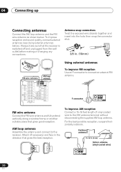
...or another suitable place that gives the best reception. To improve AM reception Connect a 15-18 feet length of vinyl-coated wire to the receiver. 04 Connecting up Connecting antennas Connect the AM loop antenna and the FM wire antenna as shown below ). For the best possible reception, ... DVD PREOUT / LD IN S-VIDEO To improve FM reception Use an F connector to connect an external FM antenna. Always make sure that the receiver is switched off and unplugged from the wall outlet before making or changing any connections. Outdoor antenna 15-18 ft. (5-6m) Indoor antenna (vinyl...
...or another suitable place that gives the best reception. To improve AM reception Connect a 15-18 feet length of vinyl-coated wire to the receiver. 04 Connecting up Connecting antennas Connect the AM loop antenna and the FM wire antenna as shown below ). For the best possible reception, ... DVD PREOUT / LD IN S-VIDEO To improve FM reception Use an F connector to connect an external FM antenna. Always make sure that the receiver is switched off and unplugged from the wall outlet before making or changing any connections. Outdoor antenna 15-18 ft. (5-6m) Indoor antenna (vinyl...
Installation Manual
Page 21
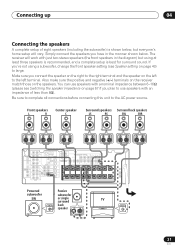
...the speaker impedance on the left to the left terminal. Connecting up 04 Connecting the speakers A complete setup of less than 8Ω). The receiver will work with just two stereo speakers (the front speakers in the manner shown below , but using at least three speakers is recommended,...nominal impedance between 6-16Ω (please see Speaker setting on the speakers. Also make sure the positive and negative (+/-) terminals on the receiver match those on page 43) to the AC power source. Be sure to complete all connections before connecting this unit to large. Simply ...
...the speaker impedance on the left to the left terminal. Connecting up 04 Connecting the speakers A complete setup of less than 8Ω). The receiver will work with just two stereo speakers (the front speakers in the manner shown below , but using at least three speakers is recommended,...nominal impedance between 6-16Ω (please see Speaker setting on the speakers. Also make sure the positive and negative (+/-) terminals on the receiver match those on page 43) to the AC power source. Be sure to complete all connections before connecting this unit to large. Simply ...
Installation Manual
Page 22
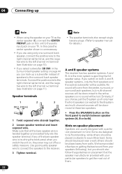
... the right channel (+) terminal, and the negative wire to speaker manual for details.) A and B speaker systems The receiver has two speaker systems: A and B. Use good quality speaker wire to connect the speakers to the receiver. 3 Tighten terminal. • The speaker terminals also accept single banana plugs. (Refer to the left channel (-) terminal...
... the right channel (+) terminal, and the negative wire to speaker manual for details.) A and B speaker systems The receiver has two speaker systems: A and B. Use good quality speaker wire to connect the speakers to the receiver. 3 Tighten terminal. • The speaker terminals also accept single banana plugs. (Refer to the left channel (-) terminal...
Installation Manual
Page 23
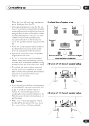
... TV in the event of external shocks such as discoloration of the picture when the TV is touching the rear panel, this may cause the receiver to turn off automatically. 3-D view of the TV picture, move the speakers farther away from the TV. • Place the center speaker above or below...
... TV in the event of external shocks such as discoloration of the picture when the TV is touching the rear panel, this may cause the receiver to turn off automatically. 3-D view of the TV picture, move the speakers farther away from the TV. • Place the center speaker above or below...


