
Owner Manual
Page 1
Audio Video Control Tuner Amplifier TX-SV535 Instruction Manual RI OSP I= 0 O 133:7,±7,1 Co= CI .1t CONTENTS Features 2 important Safeguards 3 Precautions 4 Supplied accessories 4 Before using this unit 5 Explanation 6 Speaker placement. ...Antenna connections 12 Connection for Multiple-Room Remote Control 14 Control positions and Italics 16 Listening to your favourite source...........18 Using the tuner 20 Receiving RDS (European !Timid only) 22 Entering station names (European model only) 24 Use of surround mode 25 Recording a source 27 Listening to...
Audio Video Control Tuner Amplifier TX-SV535 Instruction Manual RI OSP I= 0 O 133:7,±7,1 Co= CI .1t CONTENTS Features 2 important Safeguards 3 Precautions 4 Supplied accessories 4 Before using this unit 5 Explanation 6 Speaker placement. ...Antenna connections 12 Connection for Multiple-Room Remote Control 14 Control positions and Italics 16 Listening to your favourite source...........18 Using the tuner 20 Receiving RDS (European !Timid only) 22 Entering station names (European model only) 24 Use of surround mode 25 Recording a source 27 Listening to...

Owner Manual
Page 2
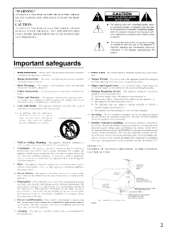
...for a Class B digital device, pursuant to Part 15 of the Onkyo A/ V Tuner Amplifier. your TX-SV535 gives you a choice of pristine power drives your home theater system to comply with the instructions. ONKYO EUROPE ELECTRONICS GMBH INDUSTRIESTRASSE 18/20 821 10 GERMERING. NOTE: This ...the equipment. Features ■ Powerful A/V Receiver with requirements of cable entry as practical . Stereo mode: 80 watts per channel (8 ohms) to your mood. ■ IPM System Onkyo's Intelligent Power Management (IPM) system switches on the TX-SV535 and automatically selects Video-1 when you ...
...for a Class B digital device, pursuant to Part 15 of the Onkyo A/ V Tuner Amplifier. your TX-SV535 gives you a choice of pristine power drives your home theater system to comply with the instructions. ONKYO EUROPE ELECTRONICS GMBH INDUSTRIESTRASSE 18/20 821 10 GERMERING. NOTE: This ...the equipment. Features ■ Powerful A/V Receiver with requirements of cable entry as practical . Stereo mode: 80 watts per channel (8 ohms) to your mood. ■ IPM System Onkyo's Intelligent Power Management (IPM) system switches on the TX-SV535 and automatically selects Video-1 when you ...
Owner Manual
Page 3
... a risk of the plug. 12. NO USER -SERVICEABLE PARTS INSIDE. such as recommended hy the manulacturer. 14. stoves. The appliance does not appear to the receiver. LEAD IN WIRE GROUND CLAMP ELECTRIC SERVICE EQUIPMENT NEC NATIONAL El FCTRICAL CODF S2898A .ANTENNA DISCHARGE UNIT (NEC SECTION 810-20, GROUNDING CONDUCTORS (NEC SECTION...
... a risk of the plug. 12. NO USER -SERVICEABLE PARTS INSIDE. such as recommended hy the manulacturer. 14. stoves. The appliance does not appear to the receiver. LEAD IN WIRE GROUND CLAMP ELECTRIC SERVICE EQUIPMENT NEC NATIONAL El FCTRICAL CODF S2898A .ANTENNA DISCHARGE UNIT (NEC SECTION 810-20, GROUNDING CONDUCTORS (NEC SECTION...

Owner Manual
Page 6
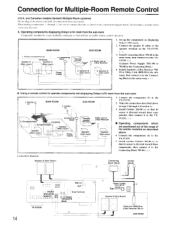
... Multi-Room System: Dinky Link: Model No. 480B-009 or J-Box Receiver: Model No. 780-10 Connecting Block: Model No. 789-40 l20VAC Power Supply: Model ... The following equipment (manufactured by ON KYO. Stage reflections reflec5ons I H • Consult your Onkyo Multi-Room System with any questions concerning Xantech's Multi-Room System. 2. and surround effects and... classical music. Secondary Remote Control For Multi-Room Remote System: Model No. Since the TX-SV535 is especially suitable for using the Multi-Room System: * Sensor Unit: Model No. ...
... Multi-Room System: Dinky Link: Model No. 480B-009 or J-Box Receiver: Model No. 780-10 Connecting Block: Model No. 789-40 l20VAC Power Supply: Model ... The following equipment (manufactured by ON KYO. Stage reflections reflec5ons I H • Consult your Onkyo Multi-Room System with any questions concerning Xantech's Multi-Room System. 2. and surround effects and... classical music. Secondary Remote Control For Multi-Room Remote System: Model No. Since the TX-SV535 is especially suitable for using the Multi-Room System: * Sensor Unit: Model No. ...
Owner Manual
Page 9
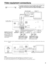
VIDEO OUT AUDIO OUT VIDEO IN GO= Video cassette recorder 0 0 Video cassette recorder IPM system: The receiver's power is automatically turned on when the TV is turned on the TV. 9 To use of a common TV/FM antenna (see antenna section). Video equipment ... player Monitor TV VIDEO OUT AUDIO OUT 000 VIDEO IN The IPM switch is swiched on. • In order to use the IPM function, the TX-SV535 should be connected to OFF. 0 0 0 0 00 0 MONITOR .0„ 0 t 90000 **0000 OUT 8 -LF Interference may be caused between the TV and this unit and the TV...
VIDEO OUT AUDIO OUT VIDEO IN GO= Video cassette recorder 0 0 Video cassette recorder IPM system: The receiver's power is automatically turned on when the TV is turned on the TV. 9 To use of a common TV/FM antenna (see antenna section). Video equipment ... player Monitor TV VIDEO OUT AUDIO OUT 000 VIDEO IN The IPM switch is swiched on. • In order to use the IPM function, the TX-SV535 should be connected to OFF. 0 0 0 0 00 0 MONITOR .0„ 0 t 90000 **0000 OUT 8 -LF Interference may be caused between the TV and this unit and the TV...
Owner Manual
Page 11
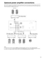
...to the power amp. or additional Receiver OOOO OOO - or additional Receiver Power amplifier, Integrated Amp. or additional Receiver 0 O OOOO OOO Surround L Surround R Front L Front R Center NOTE: • If integrated Amp. a a Power amplifier, Integrated Amp. With a powerful power amp, you will have the benefit of the TX-SV535, and connect the speakers to ... is turned off. • No signals will be output from MULTI SOURCE PRE OUT when the SPEAKERS REMOTE button is equipped with the TX-SV535 alone. Optional power amplifier connections The TX-SV535 is turned off. 11
...to the power amp. or additional Receiver OOOO OOO - or additional Receiver Power amplifier, Integrated Amp. or additional Receiver 0 O OOOO OOO Surround L Surround R Front L Front R Center NOTE: • If integrated Amp. a a Power amplifier, Integrated Amp. With a powerful power amp, you will have the benefit of the TX-SV535, and connect the speakers to ... is turned off. • No signals will be output from MULTI SOURCE PRE OUT when the SPEAKERS REMOTE button is equipped with the TX-SV535 alone. Optional power amplifier connections The TX-SV535 is turned off. 11

Owner Manual
Page 12
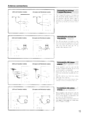
... ohm adaptor (Wotidwide models) lorosen the screws and wrap the wire around these screws. Insert wire. 3. use a common FM/TV (or VCR I type splitter To receiver To TV (or VCR) Insert into slit C. 3. FM/TV Outdoor Antenna ,, Indoor 1 T-shaped / Antenna 300 ohm ribbon wire 2 3 -- With your fingernail or a small screwdriver, press...
... ohm adaptor (Wotidwide models) lorosen the screws and wrap the wire around these screws. Insert wire. 3. use a common FM/TV (or VCR I type splitter To receiver To TV (or VCR) Insert into slit C. 3. FM/TV Outdoor Antenna ,, Indoor 1 T-shaped / Antenna 300 ohm ribbon wire 2 3 -- With your fingernail or a small screwdriver, press...
Owner Manual
Page 13
... in the direction and position where yon reccae the clearest sound. Fxtend the antenna arid move it in various directions until the clearest signal is received. Antenna connections (USA and Canadian models) AV - speaker cables and power cord. "4NA O (European and Worldwide models) AN'FNNA...
... in the direction and position where yon reccae the clearest sound. Fxtend the antenna arid move it in various directions until the clearest signal is received. Antenna connections (USA and Canadian models) AV - speaker cables and power cord. "4NA O (European and Worldwide models) AN'FNNA...
Owner Manual
Page 14
... Speaker B (Sub Room) Dinky link 480B-00 or J-Box Receiver 780-10 SUB ROOM Connecting block - Dinky Link or J-Box Receiver 2. Set up the components (a) displaying Onkyo's R I . Emitter (e) 4. Speaker r rSpeaker (Sub room) ' (Sub room) ' v 1 I mark. 2. Connect the components (d) to the speaker terminal on the TX-SV535. ( 3. Speaker B (Sub room) 1. S. Install another Emitter 282-00 (e) so...
... Speaker B (Sub Room) Dinky link 480B-00 or J-Box Receiver 780-10 SUB ROOM Connecting block - Dinky Link or J-Box Receiver 2. Set up the components (a) displaying Onkyo's R I . Emitter (e) 4. Speaker r rSpeaker (Sub room) ' (Sub room) ' v 1 I mark. 2. Connect the components (d) to the speaker terminal on the TX-SV535. ( 3. Speaker B (Sub room) 1. S. Install another Emitter 282-00 (e) so...
Owner Manual
Page 16
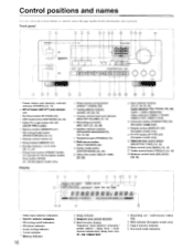
... number listed in the brackets after each item. Dell CON HUL LINEN AM -1_, CO RI DSP COR.DS 3 00 3 1 Power button and stand-by received indicator (POWER) [18, 19] 2 MR off indicators 4 FM stereo indicator 5 Audio muting indicator 6 Tuned indicator 7 Memory indicator 16 8 Sleep indicator :9) Selective tone control indicator ;10...
... number listed in the brackets after each item. Dell CON HUL LINEN AM -1_, CO RI DSP COR.DS 3 00 3 1 Power button and stand-by received indicator (POWER) [18, 19] 2 MR off indicators 4 FM stereo indicator 5 Audio muting indicator 6 Tuned indicator 7 Memory indicator 16 8 Sleep indicator :9) Selective tone control indicator ;10...
Owner Manual
Page 17
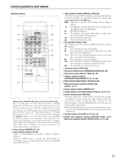
... . 04 - : Fast forward from the speakers or headphone by operating this button to set . The sleep timer is a function which was received preciously is pressed during 5 seconds, the timer setting changes. PHONO. Selection of the current track and again to skip hack to the previous track...panel display shows 10 minutes or less, the sleep timer is lit. CD. TAPE-2. Tape oeration buttons (DECK-A, DECK-B) These buttons control ONKYO double cassette tape decks that display. 10 minutes will be remote controlled. in the recording stand-by mode, recording begins. 4114 : Fast...
... . 04 - : Fast forward from the speakers or headphone by operating this button to set . The sleep timer is a function which was received preciously is pressed during 5 seconds, the timer setting changes. PHONO. Selection of the current track and again to skip hack to the previous track...panel display shows 10 minutes or less, the sleep timer is lit. CD. TAPE-2. Tape oeration buttons (DECK-A, DECK-B) These buttons control ONKYO double cassette tape decks that display. 10 minutes will be remote controlled. in the recording stand-by mode, recording begins. 4114 : Fast...
Owner Manual
Page 18
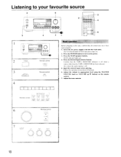
... the unit, confirm that all connections have been made properly. 1. nm 00= 000 3 4 7 3 2 olo E+J C7 C7 =1 o 4 00 0 0 0 0 0 0 0 0 0 0 0 0 0 0 0 0 OI 0 0 0 0 0 6 0 0 0: I= 0 t I I 0 0 0 0 °. Confirm that unit. 6. The STAND-BY/RECEIVED indicator comes on the remote control. 7. Start the selected input source playing. Press the desired input selector button. Follow the operating instructions of that the...
... the unit, confirm that all connections have been made properly. 1. nm 00= 000 3 4 7 3 2 olo E+J C7 C7 =1 o 4 00 0 0 0 0 0 0 0 0 0 0 0 0 0 0 0 0 OI 0 0 0 0 0 6 0 0 0: I= 0 t I I 0 0 0 0 °. Confirm that unit. 6. The STAND-BY/RECEIVED indicator comes on the remote control. 7. Start the selected input source playing. Press the desired input selector button. Follow the operating instructions of that the...
Owner Manual
Page 19
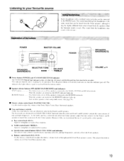
...--TREBLE POWER a O O0 0 0 0 0 0 CIC 0 0 = 0 O o o o 0I o SPEAKERS MAIN/REMOTE VOLUME •/• • Power button (POWER) and STAND-BY/RECEIVED indicator The STAND-BY/RECEIVED indicator comes on or off the speakers connected to the MAIN. The sound heard through the headphones is the ime sound that this... unit is received from the headphones may he connected to clearly reproduce ultra low and high frequencies. The indicator also lights when a signal is ...
...--TREBLE POWER a O O0 0 0 0 0 0 CIC 0 0 = 0 O o o o 0I o SPEAKERS MAIN/REMOTE VOLUME •/• • Power button (POWER) and STAND-BY/RECEIVED indicator The STAND-BY/RECEIVED indicator comes on or off the speakers connected to the MAIN. The sound heard through the headphones is the ime sound that this... unit is received from the headphones may he connected to clearly reproduce ultra low and high frequencies. The indicator also lights when a signal is ...
Owner Manual
Page 20
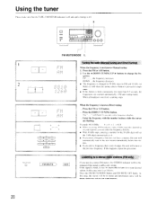
... below that sta- Press the FM or AM button. 2. Press the DIRECT TUNING button. Example: 88. 10 MHz 8 K (1/1(1 • When receiving AM broadcasts with the number buttons while the cursor are scanned automatically. (FM auto tuning mode) When a broadcast is sufficiently strong. tion. • ...a stereo FM station, the STEREO indicator will he impossible to tune in mono and interstation noise will he illuminated if the signal is received, scanning stops. The "-- will flash 16 seconds in as follows. In this happens, repeat the procedure. UP the frequency increases. If...
... below that sta- Press the FM or AM button. 2. Press the DIRECT TUNING button. Example: 88. 10 MHz 8 K (1/1(1 • When receiving AM broadcasts with the number buttons while the cursor are scanned automatically. (FM auto tuning mode) When a broadcast is sufficiently strong. tion. • ...a stereo FM station, the STEREO indicator will he impossible to tune in mono and interstation noise will he illuminated if the signal is received, scanning stops. The "-- will flash 16 seconds in as follows. In this happens, repeat the procedure. UP the frequency increases. If...
Owner Manual
Page 21
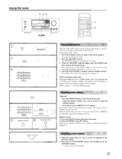
... the display changes in the following order each time the button is no PS. When the station that you want to receive by using the number buttons. The group shown on the display. 21 El Press the PRESET ( A or V )... o 0 0 0 00000 o ,o 0 0 I f= 0 0 0 !O O 0 I= o o o oo = o o ro = o o 2 MEMORY O 3 GRCUs MEMORY o 4 ABC DES INNO TAR 1 6' a STT VWX I )1 (I 55 GROUP ABC DES 1 JK NINC TOR I I I will be received for 5 seconds (for each station). ton to select the desired group. While the MEMORY indicator lights, press the GROUP but- Programming radio station 1.
... the display changes in the following order each time the button is no PS. When the station that you want to receive by using the number buttons. The group shown on the display. 21 El Press the PRESET ( A or V )... o 0 0 0 00000 o ,o 0 0 I f= 0 0 0 !O O 0 I= o o o oo = o o ro = o o 2 MEMORY O 3 GRCUs MEMORY o 4 ABC DES INNO TAR 1 6' a STT VWX I )1 (I 55 GROUP ABC DES 1 JK NINC TOR I I I will be received for 5 seconds (for each station). ton to select the desired group. While the MEMORY indicator lights, press the GROUP but- Programming radio station 1.
Owner Manual
Page 22
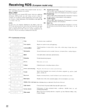
... unit. NOTE: In some cases, the characters displayed on current events and happenings. TP: Traffic Program When an RDS station broadcasting TP information is received, the traffic information will be displayed. Current affairs Topical reporting of major orchestral works. Information General information such as opposed to Pop. quizzes. II .... 13 Light classics Classical music for example) you with various services so that cannot be exactly the same as the ones broadcast by the TX-SV535. symphonies, chamber music etc. Jazz, Rhythm & Blues. Country, Reggae. 22
... unit. NOTE: In some cases, the characters displayed on current events and happenings. TP: Traffic Program When an RDS station broadcasting TP information is received, the traffic information will be displayed. Current affairs Topical reporting of major orchestral works. Information General information such as opposed to Pop. quizzes. II .... 13 Light classics Classical music for example) you with various services so that cannot be exactly the same as the ones broadcast by the TX-SV535. symphonies, chamber music etc. Jazz, Rhythm & Blues. Country, Reggae. 22

Owner Manual
Page 23
... an RDS station. Press the SCAN button to start searching for a station which broadcasts your favorite category (PTY scan) 1. If the unit cannot receive any TP station. Use the AI DOWN TUNING UP ► buttons to select the program type (PTY) (for the chosen PTY station. Each...button, to select "TP". When a station is reached, press SCAN button again to start searching for example, "ROCK M"). When the desired station is received with the desired PTY, the scanning stops for 3 seconds and indicates that the current station is shown on the display, it stops scanning. If P ...
... an RDS station. Press the SCAN button to start searching for a station which broadcasts your favorite category (PTY scan) 1. If the unit cannot receive any TP station. Use the AI DOWN TUNING UP ► buttons to select the program type (PTY) (for the chosen PTY station. Each...button, to select "TP". When a station is reached, press SCAN button again to start searching for example, "ROCK M"). When the desired station is received with the desired PTY, the scanning stops for 3 seconds and indicates that the current station is shown on the display, it stops scanning. If P ...
Owner Manual
Page 24
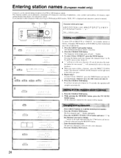
... broadcast at a time. Press the GROUP and number button. Changing existing characters. Enter the desired character. is received. 2. The frequency in memory 1. To enter O from "ONKYO", press the SMNO button and select N. Press the CHARACTER button. N, and O, one second, "_- will be... want to the left when pressing the A DOWN button. 4 . All the characters entered for each time changes the character from "ONKYO" press the 4JKL button and select K. 5. Entering station names (European model only) Characters can be input ABCDEFGHIJKLMNOPQRSTUVWXY Z1 234 56789 ...
... broadcast at a time. Press the GROUP and number button. Changing existing characters. Enter the desired character. is received. 2. The frequency in memory 1. To enter O from "ONKYO", press the SMNO button and select N. Press the CHARACTER button. N, and O, one second, "_- will be... want to the left when pressing the A DOWN button. 4 . All the characters entered for each time changes the character from "ONKYO" press the 4JKL button and select K. 5. Entering station names (European model only) Characters can be input ABCDEFGHIJKLMNOPQRSTUVWXY Z1 234 56789 ...
Owner Manual
Page 29
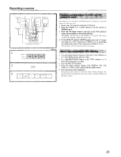
... be used . 1. Mixing video and audio for recording) Monitor TV INPUT VIDEO INPUT AUDIO CEO AUDIO O INPUT c)Voo A a' ro oborc>i Rear panel of TX-SV535 ,Pu , SELF 'JP 3 REC OUT TAPE-1 TAPE-2 MONITOR Am PHONE CD Playback and recording of TV picture and FM/ CABLE TV sound Recording of the... equipment. Press the REC OUT button. 4. Recording a source TV antenna VCR OUTPUT VIOF0 AUDIO FM an.enra VCR (for VCR recording I. Receive the TV broadcast using one VCR (connected to VIDEO-2 (or 3)) and begin recording on the VCR (VIDEO-2 or 3) that will be left as is...
... be used . 1. Mixing video and audio for recording) Monitor TV INPUT VIDEO INPUT AUDIO CEO AUDIO O INPUT c)Voo A a' ro oborc>i Rear panel of TX-SV535 ,Pu , SELF 'JP 3 REC OUT TAPE-1 TAPE-2 MONITOR Am PHONE CD Playback and recording of TV picture and FM/ CABLE TV sound Recording of the... equipment. Press the REC OUT button. 4. Recording a source TV antenna VCR OUTPUT VIOF0 AUDIO FM an.enra VCR (for VCR recording I. Receive the TV broadcast using one VCR (connected to VIDEO-2 (or 3)) and begin recording on the VCR (VIDEO-2 or 3) that will be left as is...
Owner Manual
Page 30
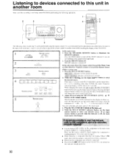
... 10 0 000 = 3 4 t73 o00 H5 03 0 0 0 0 0 0 0 0 0 0 0 0 0 0 0 I A V In the sub-room, direct the remote control toward the Dinky Link or 1 -Box Receiver (Xantech system) or toward the Remote Sensor (Onkyo system) and: 3. Press the SPEAKERS REMOTE button to illuminate the REMOTE indicator. Turn the MR OFF button off . It is recommended that... . Press the MULTI SOURCE button. Listening to devices connected to this unit in another room while watching the display of the TX-SV535. 1 Remote control EEEAKERS SPEAKERS MArN REMOTE MAIN REMOTE In the main room: 1.
... 10 0 000 = 3 4 t73 o00 H5 03 0 0 0 0 0 0 0 0 0 0 0 0 0 0 0 I A V In the sub-room, direct the remote control toward the Dinky Link or 1 -Box Receiver (Xantech system) or toward the Remote Sensor (Onkyo system) and: 3. Press the SPEAKERS REMOTE button to illuminate the REMOTE indicator. Turn the MR OFF button off . It is recommended that... . Press the MULTI SOURCE button. Listening to devices connected to this unit in another room while watching the display of the TX-SV535. 1 Remote control EEEAKERS SPEAKERS MArN REMOTE MAIN REMOTE In the main room: 1.


