
Owner Manual
Page 1
Artistry in another room 30 Trouble shooting guide 31 Specifications 32 Audio Video Control Tuner Amplifier TX-SV535 Instruction Manual RI OSP I= 0 O 133:7,±7,1 Co= CI .1t CONTENTS Features 2 important Safeguards 3 Precautions 4 Supplied accessories 4 Before using this unit 5...12 Connection for Multiple-Room Remote Control 14 Control positions and Italics 16 Listening to your favourite source...........18 Using the tuner 20 Receiving RDS (European !Timid only) 22 Entering station names (European model only) 24 Use of surround mode 25 Recording a source...
Artistry in another room 30 Trouble shooting guide 31 Specifications 32 Audio Video Control Tuner Amplifier TX-SV535 Instruction Manual RI OSP I= 0 O 133:7,±7,1 Co= CI .1t CONTENTS Features 2 important Safeguards 3 Precautions 4 Supplied accessories 4 Before using this unit 5...12 Connection for Multiple-Room Remote Control 14 Control positions and Italics 16 Listening to your favourite source...........18 Using the tuner 20 Receiving RDS (European !Timid only) 22 Entering station names (European model only) 24 Use of surround mode 25 Recording a source...

Owner Manual
Page 2
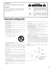
...ONKYO EUROPE ELECTRONICS GMBH INDUSTRIESTRASSE 18/20 821 10 GERMERING. These limits are designed to correct the interference by one or more of the following measures: • Reorient or relocate the receiving antenna. • Increase the separation between other equipment and receiver. • Connect the equipment into an outlet on the TX-SV535... If this manual thoroughly before making connec- which other receiver is connected. • Consult the dealer or an experienced radio/TV technician for help the TX-SV535 excel at driving accurately the most accurate surround sound). ...
...ONKYO EUROPE ELECTRONICS GMBH INDUSTRIESTRASSE 18/20 821 10 GERMERING. These limits are designed to correct the interference by one or more of the following measures: • Reorient or relocate the receiving antenna. • Increase the separation between other equipment and receiver. • Connect the equipment into an outlet on the TX-SV535... If this manual thoroughly before making connec- which other receiver is connected. • Consult the dealer or an experienced radio/TV technician for help the TX-SV535 excel at driving accurately the most accurate surround sound). ...
Owner Manual
Page 3
... plug will only tit the outlet one blade wider than the other, please read hefore the appliance is intended to alert the user to the receiver. the user should he sure the antenna system is connected to the presence of uninsulated "dangerous voltage" within the product's enclosure that they are not...
... plug will only tit the outlet one blade wider than the other, please read hefore the appliance is intended to alert the user to the receiver. the user should he sure the antenna system is connected to the presence of uninsulated "dangerous voltage" within the product's enclosure that they are not...

Owner Manual
Page 6
... The THEATER Surround mode uses Dolby Pro Logic Surround decoding, followed by additional audio processing designed by Onkyo: * Remote Emitter: Model No. Live Surround Reproduces the feeling of creating a multi-dimensional soundstage... below for using the Multi-Room System: Dinky Link: Model No. 480B-009 or J-Box Receiver: Model No. 780-10 Connecting Block: Model No. 789-40 l20VAC Power Supply: Model No...-15 for operation of a live performance. Just like in DOLBY STEREO movies. Since the TX-SV535 is applied to the musical signal to a pop concert in all audience members hear dialogue...
... The THEATER Surround mode uses Dolby Pro Logic Surround decoding, followed by additional audio processing designed by Onkyo: * Remote Emitter: Model No. Live Surround Reproduces the feeling of creating a multi-dimensional soundstage... below for using the Multi-Room System: Dinky Link: Model No. 480B-009 or J-Box Receiver: Model No. 780-10 Connecting Block: Model No. 789-40 l20VAC Power Supply: Model No...-15 for operation of a live performance. Just like in DOLBY STEREO movies. Since the TX-SV535 is applied to the musical signal to a pop concert in all audience members hear dialogue...
Owner Manual
Page 9
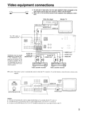
VIDEO OUT AUDIO OUT VIDEO IN GO= Video cassette recorder 0 0 Video cassette recorder IPM system: The receiver's power is automatically turned on when the TV is swiched on. • In order to use the IPM function, the TX-SV535 should be caused between the TV and this unit and the TV as far apart...
VIDEO OUT AUDIO OUT VIDEO IN GO= Video cassette recorder 0 0 Video cassette recorder IPM system: The receiver's power is automatically turned on when the TV is swiched on. • In order to use the IPM function, the TX-SV535 should be caused between the TV and this unit and the TV as far apart...
Owner Manual
Page 11
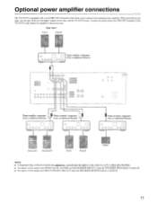
...output from MULTI SOURCE PRE OUT when the SPEAKERS REMOTE button is turned off. 11 or additional Receiver OOOO OOO - or Receiver used in the application, you to the power amp. or additional Receiver 0 O OOOO OOO Surround L Surround R Front L Front R Center NOTE: • If...the SPEAKERS MAIN button is turned off. • No signals will have the benefit of the TX-SV535, and connect the speakers to connect each external power amplifier. Optional power amplifier connections The TX-SV535 is equipped with the TX-SV535 alone. I 1 El 0 Cci s 0 OO QQ 9000000 OO o o c..» ...
...output from MULTI SOURCE PRE OUT when the SPEAKERS REMOTE button is turned off. 11 or additional Receiver OOOO OOO - or Receiver used in the application, you to the power amp. or additional Receiver 0 O OOOO OOO Surround L Surround R Front L Front R Center NOTE: • If...the SPEAKERS MAIN button is turned off. • No signals will have the benefit of the TX-SV535, and connect the speakers to connect each external power amplifier. Optional power amplifier connections The TX-SV535 is equipped with the TX-SV535 alone. I 1 El 0 Cci s 0 OO QQ 9000000 OO o o c..» ...

Owner Manual
Page 12
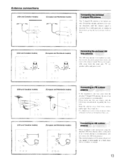
... 1 T-shaped / Antenna 300 ohm ribbon wire 2 3 -- Slit B Slit C Wire A , 5mn, .._ .) ' Directional linkage I antenna. If you must use a common FM/TV (or VCR I type splitter To receiver To TV (or VCR) Insert into slit C. 3. Insert wire. 3. Connecting the antenna cable I )r VCR) signals can interfere with pliers. Connecting the T-shaped antenna or 300...
... 1 T-shaped / Antenna 300 ohm ribbon wire 2 3 -- Slit B Slit C Wire A , 5mn, .._ .) ' Directional linkage I antenna. If you must use a common FM/TV (or VCR I type splitter To receiver To TV (or VCR) Insert into slit C. 3. Insert wire. 3. Connecting the antenna cable I )r VCR) signals can interfere with pliers. Connecting the T-shaped antenna or 300...
Owner Manual
Page 13
... a high place ahove a windoyy or outside. 13 Oa C (USA and Canadian models) r. (European and Worldwide models) O Connecting an FM outdoor antenna If the reception is received. Fix it horizontally in the direction and position where yon reccae the clearest sound. Please make sure that you stretch it with push pins or...
... a high place ahove a windoyy or outside. 13 Oa C (USA and Canadian models) r. (European and Worldwide models) O Connecting an FM outdoor antenna If the reception is received. Fix it horizontally in the direction and position where yon reccae the clearest sound. Please make sure that you stretch it with push pins or...
Owner Manual
Page 14
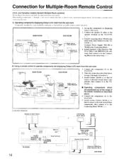
... rSpeaker (Sub room) ' (Sub room) ' v 1 I mark. 2. A. Onkyo components (a) Speaker A (Main room) TX-SV535 Speaker A (Main room) 3. Power supply Remote ,-.control 4. Dinky Link or J-Box Receiver 2. Speaker B (Sub room) 1. Emitter (e) 4. Components(b) Speake (Main room) Speaker...Receiver \. Make the connections described above in the connection diagram below to the TX-SV535. Set up the components (a) displaying Onkyo's R I . Connect the speaker B cables to the TX-SV535. 2. Components(d) TX-SV535 Connecting block 1. S. Operating components displaying Onkyo...
... rSpeaker (Sub room) ' (Sub room) ' v 1 I mark. 2. A. Onkyo components (a) Speaker A (Main room) TX-SV535 Speaker A (Main room) 3. Power supply Remote ,-.control 4. Dinky Link or J-Box Receiver 2. Speaker B (Sub room) 1. Emitter (e) 4. Components(b) Speake (Main room) Speaker...Receiver \. Make the connections described above in the connection diagram below to the TX-SV535. Set up the components (a) displaying Onkyo's R I . Connect the speaker B cables to the TX-SV535. 2. Components(d) TX-SV535 Connecting block 1. S. Operating components displaying Onkyo...
Owner Manual
Page 16
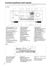
... buttons (SPEAKERS MAIN/REMOTE) [18, 19, 30] 17',; Dell CON HUL LINEN AM -1_, CO RI DSP COR.DS 3 00 3 1 Power button and stand-by received indicator (POWER) [18, 19] 2 MR off indicators 4 FM stereo indicator 5 Audio muting indicator 6 Tuned indicator 7 Memory indicator 16 8 Sleep indicator :9) Selective tone control indicator ;10...
... buttons (SPEAKERS MAIN/REMOTE) [18, 19, 30] 17',; Dell CON HUL LINEN AM -1_, CO RI DSP COR.DS 3 00 3 1 Power button and stand-by received indicator (POWER) [18, 19] 2 MR off indicators 4 FM stereo indicator 5 Audio muting indicator 6 Tuned indicator 7 Memory indicator 16 8 Sleep indicator :9) Selective tone control indicator ;10...
Owner Manual
Page 17
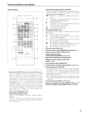
... cassette tape decks that time. C5' CD operation buttons (CD) These buttons are used to operate an ONKYO CD player with the R I A VOL = SURROUND DELAY MODE 1' E ONKYO (RI REMOTE C, ROE RC 29 16. 1 Sleep button (SLEEP) (Remote control transmitter only) Press to the beginning of the ... power off the audio muting. • Pressing this time, the amount of time remaining on the main unit. The sleep timer is a function which was received preciously is not turned oft. 2: Power button (POWER) [18, 19] '3) Input selector buttons [18, 30] NAPE-1 . the recording stand-by mode,...
... cassette tape decks that time. C5' CD operation buttons (CD) These buttons are used to operate an ONKYO CD player with the R I A VOL = SURROUND DELAY MODE 1' E ONKYO (RI REMOTE C, ROE RC 29 16. 1 Sleep button (SLEEP) (Remote control transmitter only) Press to the beginning of the ... power off the audio muting. • Pressing this time, the amount of time remaining on the main unit. The sleep timer is a function which was received preciously is not turned oft. 2: Power button (POWER) [18, 19] '3) Input selector buttons [18, 30] NAPE-1 . the recording stand-by mode,...
Owner Manual
Page 18
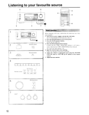
... the remote control. 7. Press the desired input selector button. Adjust the tone controls Remote control I I 1 1 1 [ INPUT SELECTOR TAPE ' TLNEP RHCNO CD [ .1 I 0 0 0 0 °. The STAND-BY/RECEIVED indicator comes on. 2. Follow the operating instructions of that the TAPE-2 MONITOR indicator is off when a source other than the TAPE-2 MONITOR has been selected...
... the remote control. 7. Press the desired input selector button. Adjust the tone controls Remote control I I 1 1 1 [ INPUT SELECTOR TAPE ' TLNEP RHCNO CD [ .1 I 0 0 0 0 °. The STAND-BY/RECEIVED indicator comes on. 2. Follow the operating instructions of that the TAPE-2 MONITOR indicator is off when a source other than the TAPE-2 MONITOR has been selected...
Owner Manual
Page 19
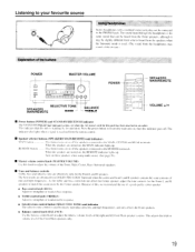
...--TREBLE POWER a O O0 0 0 0 0 0 CIC 0 0 = 0 O o o o 0I o SPEAKERS MAIN/REMOTE VOLUME •/• • Power button (POWER) and STAND-BY/RECEIVED indicator The STAND-BY/RECEIVED indicator comes on when the AC power cord for this unit has been inserted in an outlet. and R speakers contain the same amounts... of mid and high frequencies. The sound heard through the headphones is received from DOLBY PRO I.OGIC Surround when the center and front I. The indicator also lights when a signal is the ime sound that this...
...--TREBLE POWER a O O0 0 0 0 0 0 CIC 0 0 = 0 O o o o 0I o SPEAKERS MAIN/REMOTE VOLUME •/• • Power button (POWER) and STAND-BY/RECEIVED indicator The STAND-BY/RECEIVED indicator comes on when the AC power cord for this unit has been inserted in an outlet. and R speakers contain the same amounts... of mid and high frequencies. The sound heard through the headphones is received from DOLBY PRO I.OGIC Surround when the center and front I. The indicator also lights when a signal is the ime sound that this...
Owner Manual
Page 20
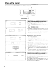
... 2. quency. will flash 16 seconds in as follows. In this case, tune in the frequency display. DE' 1 t a if When the frequency is received, scanning stops. The "-- If this unit will set the I kHz digit automatically to 0. • If you enter a frequency that sta- Select the ... and I() kHz (or 9kHzi in AM when the tuning selector button is off. 2 I . Example: 88. 10 MHz 8 K (1/1(1 • When receiving AM broadcasts with the number buttons while the cursor are scanned automatically. (FM auto tuning mode) When a broadcast is known-Direct tuning . Press the FM...
... 2. quency. will flash 16 seconds in as follows. In this case, tune in the frequency display. DE' 1 t a if When the frequency is received, scanning stops. The "-- If this unit will set the I kHz digit automatically to 0. • If you enter a frequency that sta- Select the ... and I() kHz (or 9kHzi in AM when the tuning selector button is off. 2 I . Example: 88. 10 MHz 8 K (1/1(1 • When receiving AM broadcasts with the number buttons while the cursor are scanned automatically. (FM auto tuning mode) When a broadcast is known-Direct tuning . Press the FM...
Owner Manual
Page 21
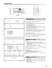
...0 00000 o ,o 0 0 I f= 0 0 0 !O O 0 I= o o o oo = o o ro = o o 2 MEMORY O 3 GRCUs MEMORY o 4 ABC DES INNO TAR 1 6' a STT VWX I )1 (I 55 GROUP ABC DES 1 JK NINC TOR I I I will be received for 5 seconds (for each station). Programming radio station 1. Select the frequency that you wish to page 22 - 24 for the RDS function) Sel preset stations... is an RDS station with a PS (Program Service Name), the frequency display will change . (Refer to receive by using the number buttons. The group shown on the display. 21 Press the MEMORY button. Press the SCAN...
...0 00000 o ,o 0 0 I f= 0 0 0 !O O 0 I= o o o oo = o o ro = o o 2 MEMORY O 3 GRCUs MEMORY o 4 ABC DES INNO TAR 1 6' a STT VWX I )1 (I 55 GROUP ABC DES 1 JK NINC TOR I I I will be received for 5 seconds (for each station). Programming radio station 1. Select the frequency that you wish to page 22 - 24 for the RDS function) Sel preset stations... is an RDS station with a PS (Program Service Name), the frequency display will change . (Refer to receive by using the number buttons. The group shown on the display. 21 Press the MEMORY button. Press the SCAN...
Owner Manual
Page 22
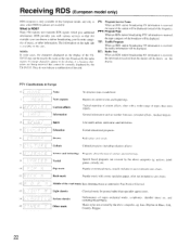
... will be displayed. Current affairs Topical reporting of major orchestral works. Jazz, Rhythm & Blues. What is received, the traffic information will be displayed. the information received from the station will be shown on this unit. quizzes. II Rock music Popular music with a wider... rather than news reports. and including Grand Opera. 15 Other music Music styles not covered by the TX-SV535. Folk. Receiving RDS (European model only) RDS reception is received. and only in past or present sales charts. They do not indicate a malfunction of the road ...
... will be displayed. Current affairs Topical reporting of major orchestral works. Jazz, Rhythm & Blues. What is received, the traffic information will be displayed. the information received from the station will be shown on this unit. quizzes. II Rock music Popular music with a wider... rather than news reports. and including Grand Opera. 15 Other music Music styles not covered by the TX-SV535. Folk. Receiving RDS (European model only) RDS reception is received. and only in past or present sales charts. They do not indicate a malfunction of the road ...

Owner Manual
Page 23
... M"). Use the AI DOWN TUNING UP ► buttons to search for the chosen PTY station. "Not find" (cannot find the station) is received, it stops scanning. this appears for approximately 5 seconds, before the unit starts scanning again. 4. See the PTY description on the display, it... indicates that even though an RDS station is being received, there is received, the characters will he shown on the display. When the desired station is broadcasting traffic information. 2. If P (' is not an...
... M"). Use the AI DOWN TUNING UP ► buttons to search for the chosen PTY station. "Not find" (cannot find the station) is received, it stops scanning. this appears for approximately 5 seconds, before the unit starts scanning again. 4. See the PTY description on the display, it... indicates that even though an RDS station is being received, there is received, the characters will he shown on the display. When the desired station is broadcasting traffic information. 2. If P (' is not an...
Owner Manual
Page 24
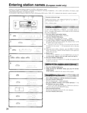
... ICH of an FM or AM broadcast station. Press the CHARACTER button. To enter O from "ONKYO" press the 4JKL button and select K. 5. If you attempt to enter characters while receiving an FM broadcast RDS station, "RDS...PS- "_" moves to recall the desired preset number. If... you have not pressed a button for 16 seconds, the operation will automatically move to M. for each time changes the character from "ONKYO", press the SMNO button and...
... ICH of an FM or AM broadcast station. Press the CHARACTER button. To enter O from "ONKYO" press the 4JKL button and select K. 5. If you attempt to enter characters while receiving an FM broadcast RDS station, "RDS...PS- "_" moves to recall the desired preset number. If... you have not pressed a button for 16 seconds, the operation will automatically move to M. for each time changes the character from "ONKYO", press the SMNO button and...
Owner Manual
Page 29
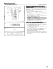
...will be sent to the monitor TV and the FM stereo sound to the speakers connected to play the video. 2. The program can be used . 1. Receive the TV broadcast using a preset button or the tuning selectors. Press the REC OUT button. 4. Press the VIDEO-2 or -3 input selector to set ... (simulcast) is . Mixing video and audio for recording) Monitor TV INPUT VIDEO INPUT AUDIO CEO AUDIO O INPUT c)Voo A a' ro oborc>i Rear panel of TX-SV535 ,Pu , SELF 'JP 3 REC OUT TAPE-1 TAPE-2 MONITOR Am PHONE CD Playback and recording of TV picture and FM/ CABLE TV sound Recording of the...
...will be sent to the monitor TV and the FM stereo sound to the speakers connected to play the video. 2. The program can be used . 1. Receive the TV broadcast using a preset button or the tuning selectors. Press the REC OUT button. 4. Press the VIDEO-2 or -3 input selector to set ... (simulcast) is . Mixing video and audio for recording) Monitor TV INPUT VIDEO INPUT AUDIO CEO AUDIO O INPUT c)Voo A a' ro oborc>i Rear panel of TX-SV535 ,Pu , SELF 'JP 3 REC OUT TAPE-1 TAPE-2 MONITOR Am PHONE CD Playback and recording of TV picture and FM/ CABLE TV sound Recording of the...
Owner Manual
Page 30
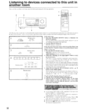
... room in advance, since it is not possible to operate the remote control in another room while watching the display of the TX-SV535. 1 Remote control EEEAKERS SPEAKERS MArN REMOTE MAIN REMOTE In the main room: 1. Remote control MULTI SOURCE f Remote control NPL...0 0 0 0 0 0 0 0 0 0 0 0 0 0 0 I A V In the sub-room, direct the remote control toward the Dinky Link or 1 -Box Receiver (Xantech system) or toward the Remote Sensor (Onkyo system) and: 3. REC OUT > indicator will he turned off . Press the MULTI SOURCE button. Press the SPEAKERS REMOTE button to illuminate the...
... room in advance, since it is not possible to operate the remote control in another room while watching the display of the TX-SV535. 1 Remote control EEEAKERS SPEAKERS MArN REMOTE MAIN REMOTE In the main room: 1. Remote control MULTI SOURCE f Remote control NPL...0 0 0 0 0 0 0 0 0 0 0 0 0 0 0 I A V In the sub-room, direct the remote control toward the Dinky Link or 1 -Box Receiver (Xantech system) or toward the Remote Sensor (Onkyo system) and: 3. REC OUT > indicator will he turned off . Press the MULTI SOURCE button. Press the SPEAKERS REMOTE button to illuminate the...


