
Owner Manual
Page 1
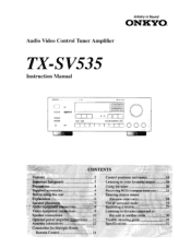
Artistry in another room 30 Trouble shooting guide 31 Specifications 32 Audio Video Control Tuner Amplifier TX-SV535 Instruction Manual RI OSP I= 0 O 133:7,±7,1 Co= CI .1t CONTENTS Features 2 important Safeguards 3 Precautions 4 Supplied accessories 4 Before using this unit 5 Explanation 6 Speaker placement. 7 Audio equipment connections 8 Video ...
Artistry in another room 30 Trouble shooting guide 31 Specifications 32 Audio Video Control Tuner Amplifier TX-SV535 Instruction Manual RI OSP I= 0 O 133:7,±7,1 Co= CI .1t CONTENTS Features 2 important Safeguards 3 Precautions 4 Supplied accessories 4 Before using this unit 5 Explanation 6 Speaker placement. 7 Audio equipment connections 8 Video ...

Owner Manual
Page 2
...the radio or any other receiver is encouraged to try to fully digital Dolby Pro Logic (for future reference. If this manual for the most accurate surround sound). Please retain this equipment dose cause harmful interference to provide reasonable protection against harmful interference in... interference will enable you get 65 watts per channel (8 ohms) to your mood. ■ IPM System Onkyo's Intelligent Power Management (IPM) system switches on the TX-SV535 and automatically selects Video-1 when you instant surround sound. ■ Multiroom and Multisource Capability You can be ...
...the radio or any other receiver is encouraged to try to fully digital Dolby Pro Logic (for future reference. If this manual for the most accurate surround sound). Please retain this equipment dose cause harmful interference to provide reasonable protection against harmful interference in... interference will enable you get 65 watts per channel (8 ohms) to your mood. ■ IPM System Onkyo's Intelligent Power Management (IPM) system switches on the TX-SV535 and automatically selects Video-1 when you instant surround sound. ■ Multiroom and Multisource Capability You can be ...
Owner Manual
Page 8
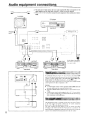
... the RI mark. For AC outlet connection RI details, refer to E in the power cord until all connections have the ONKYO R mark can be used to control ONKYO turn- Audio equipment connections Turntable O 0 PHONO OUT lHH ZH • On each component when making any other components connected... A RI I I t=i0Q oo 0 Tape deck To wall outlet Air Do not plug in the illustration at the left channel. • Please refer to the instruction manual of each pair of the AC outlets may differ according to this unit and with the R I O 0 O O O O O O O O CD player OUTPUT 1 = C=177 ...
... the RI mark. For AC outlet connection RI details, refer to E in the power cord until all connections have the ONKYO R mark can be used to control ONKYO turn- Audio equipment connections Turntable O 0 PHONO OUT lHH ZH • On each component when making any other components connected... A RI I I t=i0Q oo 0 Tape deck To wall outlet Air Do not plug in the illustration at the left channel. • Please refer to the instruction manual of each pair of the AC outlets may differ according to this unit and with the R I O 0 O O O O O O O O CD player OUTPUT 1 = C=177 ...
Owner Manual
Page 9
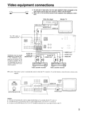
... input terminal on . AUDIO IN VIDEO IN AUDIO OUT AUDIO IN VIDEO OUT - IPM ON O (TV) (VD P) -17 Set the IPM switch to the instruction manual of each component when making any connections. Video equipment connections • On each pair of input jacks, the lower jack (marked R: Red) corresponds to the..., and the upper jack (marked L: White) to the left channel. • Please refer to ON. We do not recommend the use the IPM function, the TX-SV535 should be caused between the TV and this unit and the TV as far apart as shown in the diagram. To use this function, connect...
... input terminal on . AUDIO IN VIDEO IN AUDIO OUT AUDIO IN VIDEO OUT - IPM ON O (TV) (VD P) -17 Set the IPM switch to the instruction manual of each component when making any connections. Video equipment connections • On each pair of input jacks, the lower jack (marked R: Red) corresponds to the..., and the upper jack (marked L: White) to the left channel. • Please refer to ON. We do not recommend the use the IPM function, the TX-SV535 should be caused between the TV and this unit and the TV as far apart as shown in the diagram. To use this function, connect...
Owner Manual
Page 20
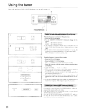
... button and FM MUTE OFF lights. If i t-' 0 0 I= I1 I 0 000 FM MUTE/MODE 1 Tuning the ratheManual tuning and Direct tuning) When the frequency is not known-Manual tuning I l i ' 0,0-1- will he illuminated if the signal is known-Direct tuning . Example: 88. 10 MHz 8 K (1/1(1 • When receiving AM broadcasts with the number buttons while...
... button and FM MUTE OFF lights. If i t-' 0 0 I= I1 I 0 000 FM MUTE/MODE 1 Tuning the ratheManual tuning and Direct tuning) When the frequency is not known-Manual tuning I l i ' 0,0-1- will he illuminated if the signal is known-Direct tuning . Example: 88. 10 MHz 8 K (1/1(1 • When receiving AM broadcasts with the number buttons while...
Owner Manual
Page 28
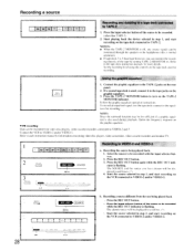
...for more details. Press the REC OUT button. VCR recording Data can monitor the recording directly of the source to the tape deck instruction manuals for recording. Recording the source being played back . Lit REC OUT REC OUT SOURCE Blink b. Recording a source r Recording and dubbing... connected to VIDEO-2 and/or VIDEO-3. Refer to be recorded with the input selector buttons. 2. Select the source to each instruction manual for recording. NOTE: Since the surround function may he recorded from the one being played back. 1. Start playing hack the device...
...for more details. Press the REC OUT button. VCR recording Data can monitor the recording directly of the source to the tape deck instruction manuals for recording. Recording the source being played back . Lit REC OUT REC OUT SOURCE Blink b. Recording a source r Recording and dubbing... connected to VIDEO-2 and/or VIDEO-3. Refer to be recorded with the input selector buttons. 2. Select the source to each instruction manual for recording. NOTE: Since the surround function may he recorded from the one being played back. 1. Start playing hack the device...
Owner Manual
Page 31
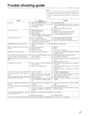
...control transmitter • Bad connections. • Check connections, speaker leads, etc. • Amplifier protection circuitry has been • Contact your ONKYO service center. lamp on and off and then on . • Switch to different position. Trouble shooting guide NOTE: If a problem occurs while...control down. not operate. • The MR OFF button on the TX-SV535 • Press the MR OFF button. (The MR OFF indicator is too strong. • Change to the respective instruction manuals of the TX-SV535. Power but • Station is engaged. (The MR OFF indicator ...
...control transmitter • Bad connections. • Check connections, speaker leads, etc. • Amplifier protection circuitry has been • Contact your ONKYO service center. lamp on and off and then on . • Switch to different position. Trouble shooting guide NOTE: If a problem occurs while...control down. not operate. • The MR OFF button on the TX-SV535 • Press the MR OFF button. (The MR OFF indicator is too strong. • Change to the respective instruction manuals of the TX-SV535. Power but • Station is engaged. (The MR OFF indicator ...

