
Owner Manual
Page 1
... Control Tuner Amplifier TX-SV535 Instruction Manual RI OSP I= 0 O 133:7,±7,1 Co= CI .1t CONTENTS Features 2 important Safeguards 3 Precautions 4 Supplied accessories 4 Before using this unit 5 Explanation 6 Speaker placement. 7 Audio equipment connections 8 Video equipment con4ctions 9 Speaker connections 10 Optional power amplifier connections ....11 Antenna connections 12 Connection for Multiple-Room Remote Control 14 Control...
... Control Tuner Amplifier TX-SV535 Instruction Manual RI OSP I= 0 O 133:7,±7,1 Co= CI .1t CONTENTS Features 2 important Safeguards 3 Precautions 4 Supplied accessories 4 Before using this unit 5 Explanation 6 Speaker placement. 7 Audio equipment connections 8 Video equipment con4ctions 9 Speaker connections 10 Optional power amplifier connections ....11 Antenna connections 12 Connection for Multiple-Room Remote Control 14 Control...

Owner Manual
Page 2
...Stereo mode: 80 watts per channel to CATV system installer: • This reminder is in a particular installation. Your authorized Onkyo service center has details.) ■ R I Compatible Remote Control ■ Useful Extras You'll Enjoy • 3 Video and 6 audio Inputs • Heavy-duty, multiway ...or modifications not expressly approved by turning the equipment off and on your mood. ■ IPM System Onkyo's Intelligent Power Management (IPM) system switches on the TX-SV535 and automatically selects Video-1 when you a choice of the FCC Rules. This equipment generates, uses, ...
...Stereo mode: 80 watts per channel to CATV system installer: • This reminder is in a particular installation. Your authorized Onkyo service center has details.) ■ R I Compatible Remote Control ■ Useful Extras You'll Enjoy • 3 Video and 6 audio Inputs • Heavy-duty, multiway ...or modifications not expressly approved by turning the equipment off and on your mood. ■ IPM System Onkyo's Intelligent Power Management (IPM) system switches on the TX-SV535 and automatically selects Video-1 when you a choice of the FCC Rules. This equipment generates, uses, ...

Owner Manual
Page 4
... the chassis and is unplugged. dampen a soft cloth in a safe place. 2. Copy the serial number and model number onto your Onkyo authorized service station. 1 Remote control 2 Batteries (size AA, R6, or UM-3) 1 Remote control cable 4. If power does not come on the rear panel of this switch to set this unit. and the...
... the chassis and is unplugged. dampen a soft cloth in a safe place. 2. Copy the serial number and model number onto your Onkyo authorized service station. 1 Remote control 2 Batteries (size AA, R6, or UM-3) 1 Remote control cable 4. If power does not come on the rear panel of this switch to set this unit. and the...
Owner Manual
Page 5
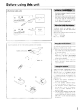
TX-SV535 Remote control sensor 0 30 approx. 5m 0 rirrr the Voltage selector 1. If the preset voltage is not correct for your area. Slide the switch all the way to the right ( I gggg KA ▪ 00000 00 ggggggggggg 00 AM FREQ STEP 9 KHz 10 kHz Insert the batteries into the remote control ... help you get optimal use from direct bright light, which can prevent proper operation of approximately six months. If this unit away from the remote control. • Place this unit is appropriate. depending on frequency of usage. • This unit comes equipped with this unit have a...
TX-SV535 Remote control sensor 0 30 approx. 5m 0 rirrr the Voltage selector 1. If the preset voltage is not correct for your area. Slide the switch all the way to the right ( I gggg KA ▪ 00000 00 ggggggggggg 00 AM FREQ STEP 9 KHz 10 kHz Insert the batteries into the remote control ... help you get optimal use from direct bright light, which can prevent proper operation of approximately six months. If this unit away from the remote control. • Place this unit is appropriate. depending on frequency of usage. • This unit comes equipped with this unit have a...

Owner Manual
Page 6
... amplifier and Surround amplifiers. HE-10 • Use the secondary remote control model indicated below for oper- and surround effects and ambience emanating from the reflections and rever- Since the TX-SV535 is equipped with the increased channel separation it gives a tar greater...can he produced. rately) is produced from the sides and rear of a live performance. Stage reflections reflec5ons I H • Consult your Onkyo Multi-Room System with a Xantech Multi-Room System. ARENA Surround "this mode for details. ) 1. NOTES: • The concert hall ...
... amplifier and Surround amplifiers. HE-10 • Use the secondary remote control model indicated below for oper- and surround effects and ambience emanating from the reflections and rever- Since the TX-SV535 is equipped with the increased channel separation it gives a tar greater...can he produced. rately) is produced from the sides and rear of a live performance. Stage reflections reflec5ons I H • Consult your Onkyo Multi-Room System with a Xantech Multi-Room System. ARENA Surround "this mode for details. ) 1. NOTES: • The concert hall ...
Owner Manual
Page 8
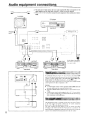
...details, refer to E in the power cord until all connections have the ONKYO R mark can be used to the black jack with any connections. Be careful that other components. ( ) NOTES: • To enable proper remote control operation, both the R I cable and the audio cables must be...; o0 0 Tape deck LINE IN LINE OUT 1.1 21IFTFIlk CS= =I O 0 O O O O O O O O CD player OUTPUT 1 = C=177 mom= See page 14-15. Connect a remote control cable to control ONKYO turn- I=I t=i0Q oo 0 Tape deck To wall outlet Air Do not plug in the illustration at the left channel. • Please refer to...
...details, refer to E in the power cord until all connections have the ONKYO R mark can be used to the black jack with any connections. Be careful that other components. ( ) NOTES: • To enable proper remote control operation, both the R I cable and the audio cables must be...; o0 0 Tape deck LINE IN LINE OUT 1.1 21IFTFIlk CS= =I O 0 O O O O O O O O CD player OUTPUT 1 = C=177 mom= See page 14-15. Connect a remote control cable to control ONKYO turn- I=I t=i0Q oo 0 Tape deck To wall outlet Air Do not plug in the illustration at the left channel. • Please refer to...

Owner Manual
Page 10
... the lever. Insert woe. NOTE: To prevent damage to pages 14, 15) Front L (A) F ont R (A) ■ Speaker impedance FRONT MAIN: 6 ohms min./speaker CENTER, REAR, FRONT REMOTE: 8 ohms min./speaker 10 O Sc 5. Speaker connections . 1 8mm 2. ( ft C 4. NO Connecting the front and rear (surround) speakers Connecting of center speaker and subwoofer If you...
... the lever. Insert woe. NOTE: To prevent damage to pages 14, 15) Front L (A) F ont R (A) ■ Speaker impedance FRONT MAIN: 6 ohms min./speaker CENTER, REAR, FRONT REMOTE: 8 ohms min./speaker 10 O Sc 5. Speaker connections . 1 8mm 2. ( ft C 4. NO Connecting the front and rear (surround) speakers Connecting of center speaker and subwoofer If you...
Owner Manual
Page 11
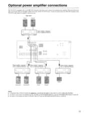
... Front L Front R Center NOTE: • If integrated Amp. Optional power amplifier connections The TX-SV535 is turned off . • No signals will be output from MULTI SOURCE PRE OUT when the SPEAKERS REMOTE button is equipped with a set of PRE OUT terminals which allow you can play music at ...even higher volume levels than with the TX-SV535 alone. Sub room Front L Front R Power amplifier, Integrated 0 O Amp. ...
... Front L Front R Center NOTE: • If integrated Amp. Optional power amplifier connections The TX-SV535 is turned off . • No signals will be output from MULTI SOURCE PRE OUT when the SPEAKERS REMOTE button is equipped with a set of PRE OUT terminals which allow you can play music at ...even higher volume levels than with the TX-SV535 alone. Sub room Front L Front R Power amplifier, Integrated 0 O Amp. ...
Owner Manual
Page 14
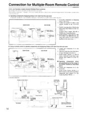
...) Connecting block 789-40, Emitter 282-00 O 5 14 t _J o FRONT SPEAKERS co 00 C O (REMOTE ) c o o O. Connect the speaker B cables to the TX-SV535. and Canadian models (Xantech Multiple-Room systems) Do not plug in steps 2 through 5 , he c mected as...(Main room) Power supply SUB ROOM r -Remote ,control Dinky Link or -J-Box Receiver \. Onkyo components (a) Speaker A (Main room) TX-SV535 Speaker A (Main room) 3. Connect the components (d) to the speaker terminal on the TX-SV535. ( 3. S. Connection for Multiple-Room Remote Control U.S.A. MAIN ROOM SUB ROOM 1. Speaker...
...) Connecting block 789-40, Emitter 282-00 O 5 14 t _J o FRONT SPEAKERS co 00 C O (REMOTE ) c o o O. Connect the speaker B cables to the TX-SV535. and Canadian models (Xantech Multiple-Room systems) Do not plug in steps 2 through 5 , he c mected as...(Main room) Power supply SUB ROOM r -Remote ,control Dinky Link or -J-Box Receiver \. Onkyo components (a) Speaker A (Main room) TX-SV535 Speaker A (Main room) 3. Connect the components (d) to the speaker terminal on the TX-SV535. ( 3. S. Connection for Multiple-Room Remote Control U.S.A. MAIN ROOM SUB ROOM 1. Speaker...
Owner Manual
Page 15
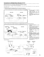
... the components (c) to the speaker terminal on the TX-SV535. (11') 3. Speaker B \ (SIub room) 2. Set up the components (a) displaying Onkyo's RI mark. 2. Connect the speaker (sub room) cables to the TX-SV535. 5. Install Remote Sensor HR-10 in the power cord until all connections...these components, then connect it to the TX-SV535. (q.) (Connect the AC adapter to connect the units as shown below . MAIN ROOM 1. Onkyo components (a) Speaker A (Main room) TX-SV535 Speaker ' (Main room) 'N N \ \'' SUB ROOM Remote \r= control 3. Remote Emitter HE-50(AC) Power supply\ ...
... the components (c) to the speaker terminal on the TX-SV535. (11') 3. Speaker B \ (SIub room) 2. Set up the components (a) displaying Onkyo's RI mark. 2. Connect the speaker (sub room) cables to the TX-SV535. 5. Install Remote Sensor HR-10 in the power cord until all connections...these components, then connect it to the TX-SV535. (q.) (Connect the AC adapter to connect the units as shown below . MAIN ROOM 1. Onkyo components (a) Speaker A (Main room) TX-SV535 Speaker ' (Main room) 'N N \ \'' SUB ROOM Remote \r= control 3. Remote Emitter HE-50(AC) Power supply\ ...
Owner Manual
Page 16
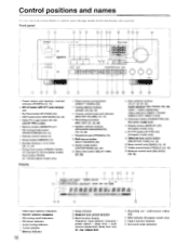
... MODE) [25, 26] 5 Dolby Pro Logic button [25, 26] (DOLBY PRO LOGIC) 6 Memory button (MEMORY) [21] 7 FM muting/mode button (FM MUTE/MODE) [20, 21] 8 Remote control sensor [5] 9 Group button (GROUP) [21] 13 Number buttons (1 to the page number listed in the brackets after each item. I RDS afi! Front panel 0 0 0 ©... indicators Volume control knob and indicator (MASTER VOLUME) [18, 19] 15, Recording out button (REC OUT) [27, 28, 29] 16', Speaker selector buttons (SPEAKERS MAIN/REMOTE) [18, 19, 30] 17',;
... MODE) [25, 26] 5 Dolby Pro Logic button [25, 26] (DOLBY PRO LOGIC) 6 Memory button (MEMORY) [21] 7 FM muting/mode button (FM MUTE/MODE) [20, 21] 8 Remote control sensor [5] 9 Group button (GROUP) [21] 13 Number buttons (1 to the page number listed in the brackets after each item. I RDS afi! Front panel 0 0 0 ©... indicators Volume control knob and indicator (MASTER VOLUME) [18, 19] 15, Recording out button (REC OUT) [27, 28, 29] 16', Speaker selector buttons (SPEAKERS MAIN/REMOTE) [18, 19, 30] 17',;
Owner Manual
Page 17
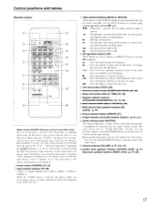
...DOWN buttons (PRESET A /V ) [21] Audio muting button (MUTING) This button temporarily switches off the power to right, or. Control positions and names Remote control 0 1 SPEA'JCS P .NEF. I CZ=t FS, 'EST I I mark. The sleep timer is a function which was received preciously is ... muting indicator 'AUDIO MUTING" will be remote controlled. Pressing the button again or using the POWER button to operate an ONKYO CD player with the R I A VOL = SURROUND DELAY MODE 1' E ONKYO (RI REMOTE C, ROE RC 29 16. 1 Sleep button (SLEEP) (Remote control transmitter only) Press to stop the...
...DOWN buttons (PRESET A /V ) [21] Audio muting button (MUTING) This button temporarily switches off the power to right, or. Control positions and names Remote control 0 1 SPEA'JCS P .NEF. I CZ=t FS, 'EST I I mark. The sleep timer is a function which was received preciously is ... muting indicator 'AUDIO MUTING" will be remote controlled. Pressing the button again or using the POWER button to operate an ONKYO CD player with the R I A VOL = SURROUND DELAY MODE 1' E ONKYO (RI REMOTE C, ROE RC 29 16. 1 Sleep button (SLEEP) (Remote control transmitter only) Press to stop the...
Owner Manual
Page 18
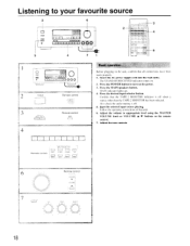
.... Follow the operating instructions of that all connections have been made properly. 1. The STAND-BY/RECEIVED indicator comes on the power. 3. Adjust the tone controls Remote control I I 1 1 1 [ INPUT SELECTOR TAPE ' TLNEP RHCNO CD [ .1 I 0 0 0 0 °. Insert the AC power supply cord into the ...Press the MAIN speakers button. Press the POWER button to appropriate level using the MASTER VOLUME knob or VOLUME A/V buttons on the remote control. 7. Confirm that the TAPE-2 MONITOR indicator is off when a source other than the TAPE-2 MONITOR has been selected. Also...
.... Follow the operating instructions of that all connections have been made properly. 1. The STAND-BY/RECEIVED indicator comes on the power. 3. Adjust the tone controls Remote control I I 1 1 1 [ INPUT SELECTOR TAPE ' TLNEP RHCNO CD [ .1 I 0 0 0 0 °. Insert the AC power supply cord into the ...Press the MAIN speakers button. Press the POWER button to appropriate level using the MASTER VOLUME knob or VOLUME A/V buttons on the remote control. 7. Confirm that the TAPE-2 MONITOR indicator is off when a source other than the TAPE-2 MONITOR has been selected. Also...
Owner Manual
Page 19
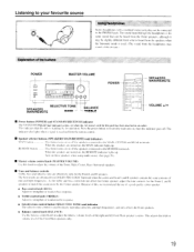
...it may sound a little distant. ) POWER MASTER VOLUME 00 0 0 0 Q 0 SELECTIVE TONE SPEAKERS MAIN/REMOTE BASS BALANCE --TREBLE POWER a O O0 0 0 0 0 0 CIC 0 0 = 0 O o o o 0I o SPEAKERS MAIN/REMOTE VOLUME •/• • Power button (POWER) and STAND-BY/RECEIVED indicator The STAND-BY/RECEIVED indicator ...connected to the MAIN. The indicator also lights when a signal is used . (The sound from the remote control. • Speaker selector buttons (SPEAKERS MAIN/REMOTE) and indicators MAIN button This button turns on these speakers when using multi source. (See page 30....
...it may sound a little distant. ) POWER MASTER VOLUME 00 0 0 0 Q 0 SELECTIVE TONE SPEAKERS MAIN/REMOTE BASS BALANCE --TREBLE POWER a O O0 0 0 0 0 0 CIC 0 0 = 0 O o o o 0I o SPEAKERS MAIN/REMOTE VOLUME •/• • Power button (POWER) and STAND-BY/RECEIVED indicator The STAND-BY/RECEIVED indicator ...connected to the MAIN. The indicator also lights when a signal is used . (The sound from the remote control. • Speaker selector buttons (SPEAKERS MAIN/REMOTE) and indicators MAIN button This button turns on these speakers when using multi source. (See page 30....
Owner Manual
Page 21
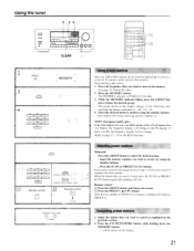
... ( A or V ) button. Programming radio station 1. Press the MEMORY button. When the station that you wish to choose the desired group. Remote control El Press the GROUP button and choose the group. MEMORY FM MUTEMODE O L CI FAR Cancelling preset stations 1. Input the memory number you.... 2. Each station stored in the group chosen in step I STIT SCAN European model only PRESET SCAN Except for the Earopean model Remote control TUNER GROUP Remote control PRESET V Using preset stations Since ten AM or FM stations can be stored in each group (A, B or C), a total...
... ( A or V ) button. Programming radio station 1. Press the MEMORY button. When the station that you wish to choose the desired group. Remote control El Press the GROUP button and choose the group. MEMORY FM MUTEMODE O L CI FAR Cancelling preset stations 1. Input the memory number you.... 2. Each station stored in the group chosen in step I STIT SCAN European model only PRESET SCAN Except for the Earopean model Remote control TUNER GROUP Remote control PRESET V Using preset stations Since ten AM or FM stations can be stored in each group (A, B or C), a total...

Owner Manual
Page 25
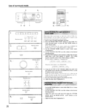
... source is selected. Use a shorter delay to a pop concert in a domed stadium. DSP MODE button or BYPASS button. (When using the remote control, press the SURROUND MODE button.) Make your listening room can decode four channel surround sound. nm I I msec during a period of I5...o o CI 0 00 0 0 00 0 ON CENTER MODE DELAY TIME DELAY TIME Explanation 1: Surround mode Dolby Pro Logic By using the delay time button of the remote control. • When you do not wish to use the Surround mode. three different modes are many surround speakers in conjunction with the input selector...
... source is selected. Use a shorter delay to a pop concert in a domed stadium. DSP MODE button or BYPASS button. (When using the remote control, press the SURROUND MODE button.) Make your listening room can decode four channel surround sound. nm I I msec during a period of I5...o o CI 0 00 0 0 00 0 ON CENTER MODE DELAY TIME DELAY TIME Explanation 1: Surround mode Dolby Pro Logic By using the delay time button of the remote control. • When you do not wish to use the Surround mode. three different modes are many surround speakers in conjunction with the input selector...
Owner Manual
Page 26
... kind of sound in your reference, adjust the center and rear speaker levels with the CENTER/REAR LEVEL A and • buttons on the remote control. If you can be experienced in each Surround mode and stored for three seconds. Use the CENTER MODE button to select Theater mode.... Live and Arena Surround parameters Use the DSP MODE button to select either PRO LOGIC or THEATER. 3. The test tone (pink noise) cycles from the remote control, press SURROUND MODE button to select either Hall, Live or Arena (Explanation 1). If Center Mode is NORMAL or WIDEBAND: left front ---* right front...
... kind of sound in your reference, adjust the center and rear speaker levels with the CENTER/REAR LEVEL A and • buttons on the remote control. If you can be experienced in each Surround mode and stored for three seconds. Use the CENTER MODE button to select Theater mode.... Live and Arena Surround parameters Use the DSP MODE button to select either PRO LOGIC or THEATER. 3. The test tone (pink noise) cycles from the remote control, press SURROUND MODE button to select either Hall, Live or Arena (Explanation 1). If Center Mode is NORMAL or WIDEBAND: left front ---* right front...
Owner Manual
Page 27
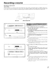
... SOURCE Blink Recording and dubbing to a tape deck connected to recording mode. Recording a source Recording an audio source Tape recording With the TX-SV535 you can be recorded and if the input selector is flashing. Press the input selector button to select the source to be recorded. (... not change . When recording a source different from FM or AM while listening to the sound of any recording device connected to disable remote control operation from another source through speakers or headphones. The source you selected to record will be recorded, (other than TAPE-1) while ...
... SOURCE Blink Recording and dubbing to a tape deck connected to recording mode. Recording a source Recording an audio source Tape recording With the TX-SV535 you can be recorded and if the input selector is flashing. Press the input selector button to select the source to be recorded. (... not change . When recording a source different from FM or AM while listening to the sound of any recording device connected to disable remote control operation from another source through speakers or headphones. The source you selected to record will be recorded, (other than TAPE-1) while ...
Owner Manual
Page 30
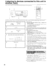
... another room while watching the display of the TX-SV535. 1 Remote control EEEAKERS SPEAKERS MArN REMOTE MAIN REMOTE In the main room: 1. MR OFF indicator...Remote control NPL, I SELECTOR TAPE TUNER EHONO CD I I I TAPE-2 VIOE0-' VIDEO-2 VIDEO-3 Remote control LEVEL I I = 0I 0 0 l 0 00 0 0 0 0 0 0 0 03331.10,3 1 4 The following operations. 2 3 10 0 000 = 3 4 t73 o00 H5 03 0 0 0 0 0 0 0 0 0 0 0 0 0 0 0 I A V In the sub-room, direct the remote control toward the Dinky Link or 1 -Box Receiver (Xantech system) or toward the Remote Sensor (Onkyo...
... another room while watching the display of the TX-SV535. 1 Remote control EEEAKERS SPEAKERS MArN REMOTE MAIN REMOTE In the main room: 1. MR OFF indicator...Remote control NPL, I SELECTOR TAPE TUNER EHONO CD I I I TAPE-2 VIOE0-' VIDEO-2 VIDEO-3 Remote control LEVEL I I = 0I 0 0 l 0 00 0 0 0 0 0 0 0 03331.10,3 1 4 The following operations. 2 3 10 0 000 = 3 4 t73 o00 H5 03 0 0 0 0 0 0 0 0 0 0 0 0 0 0 0 I A V In the sub-room, direct the remote control toward the Dinky Link or 1 -Box Receiver (Xantech system) or toward the Remote Sensor (Onkyo...
Owner Manual
Page 31
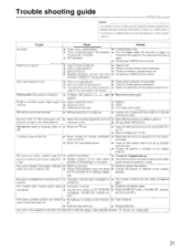
...antenna is not due to a malfunction (or worn out batteries) of the TX-SV535. control transmitter does not. Trouble shooting guide NOTE: If a problem occurs while you are using the remote control, first operate the unit using the front panel controls to confirm that ...not correct. cable on AM, FM. • Noise caused by remote control transmitter • Bad connections. • Check connections, speaker leads, etc. • Amplifier protection circuitry has been • Contact your ONKYO service center. Crackling noise on the rear panel is least. ter. ...
...antenna is not due to a malfunction (or worn out batteries) of the TX-SV535. control transmitter does not. Trouble shooting guide NOTE: If a problem occurs while you are using the remote control, first operate the unit using the front panel controls to confirm that ...not correct. cable on AM, FM. • Noise caused by remote control transmitter • Bad connections. • Check connections, speaker leads, etc. • Amplifier protection circuitry has been • Contact your ONKYO service center. Crackling noise on the rear panel is least. ter. ...


