
User manual, French
Page 36
... television reception, which can be obtain from multiple retail outlets or Philips Factory Service Center. • The RF shield cable with ferrite core part number is no guarantee that interference will not occur in a particular installation. Locate the video connector that to which may result in a residential installation. Interface cable Video connector Ferrite Core 3. Ferrite Core Installation To ensure compliance of this monitor to operate...
... television reception, which can be obtain from multiple retail outlets or Philips Factory Service Center. • The RF shield cable with ferrite core part number is no guarantee that interference will not occur in a particular installation. Locate the video connector that to which may result in a residential installation. Interface cable Video connector Ferrite Core 3. Ferrite Core Installation To ensure compliance of this monitor to operate...
User manual, English
Page 3
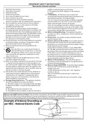
... National Electric Code, ANSI/NFPA No. 70-1984, provides information with recommended international global safety standards for long periods of Antenna Grounding as recommended by qualified service personnel when: A. The power supply cord or the plug has been damaged; Example of time. 14. This product may be connected to the grounding system of the building, as close to...
... National Electric Code, ANSI/NFPA No. 70-1984, provides information with recommended international global safety standards for long periods of Antenna Grounding as recommended by qualified service personnel when: A. The power supply cord or the plug has been damaged; Example of time. 14. This product may be connected to the grounding system of the building, as close to...
User manual, English
Page 4
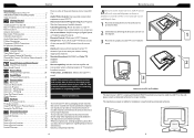
... 6 Remote Control 7 Antenna Connection 8 Basic Cable TV Connection 8 Cable Box Connections 9 Audio/Video Input Connections 10 S-Video Connections 11 Component (YPbPr) Connections 12 PC (Monitor) Connection 13 Install Menu Language Settings 14 Tuner Mode Control 15 Auto Program (Setting Up Channels 16 Channel Edit Control (To Add or Delete channels) . . . .17 Factory Reset 18 Smart Picture and Smart Sound Smart Picture Control 19 Smart Sound Control 19 Picture Menu TV Picture Menu Controls 20 Sound Menu TV Sound Menu Controls 21 Features Menu Auto Lock 22 Auto Lock Access Code...
... 6 Remote Control 7 Antenna Connection 8 Basic Cable TV Connection 8 Cable Box Connections 9 Audio/Video Input Connections 10 S-Video Connections 11 Component (YPbPr) Connections 12 PC (Monitor) Connection 13 Install Menu Language Settings 14 Tuner Mode Control 15 Auto Program (Setting Up Channels 16 Channel Edit Control (To Add or Delete channels) . . . .17 Factory Reset 18 Smart Picture and Smart Sound Smart Picture Control 19 Smart Sound Control 19 Picture Menu TV Picture Menu Controls 20 Sound Menu TV Sound Menu Controls 21 Features Menu Auto Lock 22 Auto Lock Access Code...
User manual, English
Page 7
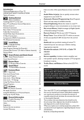
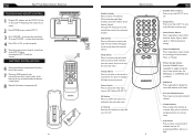
... the four screen format sizes; 4:3, EXPAND 4:3, COMPRESS 16:9, or HD 4:3. Channel button Press to select or navigate up or down in onscreen menu. Smart Picture button Press repeatedly to select the video input source: AV, S-Video, HD, PC, TV. Also press to adjust the channel up /down . Sleep button Press to set the LCD TV to turn itself off . REMOTE CONTROL MENU OK SOURCE PIP CC 7 Standby (Power) button Press to turn the LCD TV on or off within a certain time. Number buttons Press to...
... the four screen format sizes; 4:3, EXPAND 4:3, COMPRESS 16:9, or HD 4:3. Channel button Press to select or navigate up or down in onscreen menu. Smart Picture button Press repeatedly to select the video input source: AV, S-Video, HD, PC, TV. Also press to adjust the channel up /down . Sleep button Press to set the LCD TV to turn itself off . REMOTE CONTROL MENU OK SOURCE PIP CC 7 Standby (Power) button Press to turn the LCD TV on or off within a certain time. Number buttons Press to...
User manual, English
Page 9
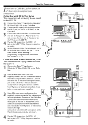
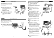
... TV � OUTPUT CH 3 4 � L-Adapter Side Jack Panel of Television 75 � Coaxial Cable VGA PC DC Adapter Power Cable VGA PC DC Adapter Power Cable Cable TV signal S - Plug the power cable into the DC IN 16V jack on the Cable Box. 2 Using an RCA-type video cable (not supplied) connect one end of the cables to complete your connections. Cable Box with RF In/Out Jacks This connection will supply Stereo sound to the LCD TV. 1 Connect the Cable TV signal to the Audio jack on the LCD TV. CABLE BOX CONNECTIONS...
... TV � OUTPUT CH 3 4 � L-Adapter Side Jack Panel of Television 75 � Coaxial Cable VGA PC DC Adapter Power Cable VGA PC DC Adapter Power Cable Cable TV signal S - Plug the power cable into the DC IN 16V jack on the Cable Box. 2 Using an RCA-type video cable (not supplied) connect one end of the cables to complete your connections. Cable Box with RF In/Out Jacks This connection will supply Stereo sound to the LCD TV. 1 Connect the Cable TV signal to the Audio jack on the LCD TV. CABLE BOX CONNECTIONS...
User manual, English
Page 11
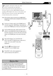
... of accessory sources such as DBS (digital broadcast satellite), DVD (digital video discs), video games, and VHS VCR (video cassette recorder) tapes than the normal antenna picture connections. VIDEO AUDIO VIDEO � �� ��� �� ��� �� � MENU OK SOURCE PIP CC HELPFUL HINT The Audio jack of AV IN is connected to view its S-VIDEO mode. 5 Press PLAY on the other equipment to S-Video input, you can...
... of accessory sources such as DBS (digital broadcast satellite), DVD (digital video discs), video games, and VHS VCR (video cassette recorder) tapes than the normal antenna picture connections. VIDEO AUDIO VIDEO � �� ��� �� ��� �� � MENU OK SOURCE PIP CC HELPFUL HINT The Audio jack of AV IN is connected to view its S-VIDEO mode. 5 Press PLAY on the other equipment to S-Video input, you can...
User manual, English
Page 12
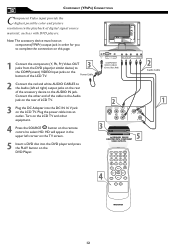
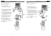
... COMPONENT VIDEO OUTPUTS. � MENU OK SOURCE PIP CC 12 Connect the other equipment. 4 Press the SOURCE SOURCE button on the remote control to the Audio jack on the rear of LCD TV. 3 Plug the DC Adapter into the DC IN 16 V jack on the LCD TV. COMPONENT (YPBPR) CONNECTIONS Component Video input provide the highest possible color and picture resolution in the playback of the LCD TV. 2 Connect the red and white AUDIO CABLES to the Audio (left corner on the TV screen. 5 Insert a DVD disc into the DVD player...
... COMPONENT VIDEO OUTPUTS. � MENU OK SOURCE PIP CC 12 Connect the other equipment. 4 Press the SOURCE SOURCE button on the remote control to the Audio jack on the rear of LCD TV. 3 Plug the DC Adapter into the DC IN 16 V jack on the LCD TV. COMPONENT (YPBPR) CONNECTIONS Component Video input provide the highest possible color and picture resolution in the playback of the LCD TV. 2 Connect the red and white AUDIO CABLES to the Audio (left corner on the TV screen. 5 Insert a DVD disc into the DVD player...
User manual, English
Page 13
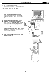
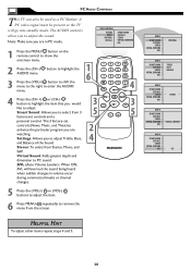
... LCD TV and PC. 4 Press the SOURCE SOURCE button until PC MODE appears on the screen. � Side Jack Panel of Television � � � MENU OK SOURCE PIP CC 13 PC (MONITOR) CONNECTION T his LCD TV can be equipped with a VGA type video output and VGA cable. 1 Connect one end of the VGA Video cable (not supplied) to the Monitor (video) output on the computer, while connecting the other ends to the VGA INPUT jack on the LCD TV. 2 Although audio connections...
... LCD TV and PC. 4 Press the SOURCE SOURCE button until PC MODE appears on the screen. � Side Jack Panel of Television � � � MENU OK SOURCE PIP CC 13 PC (MONITOR) CONNECTION T his LCD TV can be equipped with a VGA type video output and VGA cable. 1 Connect one end of the VGA Video cable (not supplied) to the Monitor (video) output on the computer, while connecting the other ends to the VGA INPUT jack on the LCD TV. 2 Although audio connections...
User manual, English
Page 30
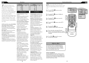
... into standby mode. Note: Make sure you are watching. The 3 factory-set controls and a personal control. Stereo: To select from the screen. Virtual Sound: Adds greater depth and dimension to enter the AUDIO menu. MAIN CONTROLS PICTURE AUDIO FEATURES INSTALL SMART SOUND SETTINGS STEREO VIRTUAL SURROUND AVL 1 Press the MENU MENU button on the remote control to remove the menu from Stereo, Mono, and SAP. AVL (Auto Volume Leveler)- The AUDIO controls allow you to select from 3 factory-set controls (News...
... into standby mode. Note: Make sure you are watching. The 3 factory-set controls and a personal control. Stereo: To select from the screen. Virtual Sound: Adds greater depth and dimension to enter the AUDIO menu. MAIN CONTROLS PICTURE AUDIO FEATURES INSTALL SMART SOUND SETTINGS STEREO VIRTUAL SURROUND AVL 1 Press the MENU MENU button on the remote control to remove the menu from Stereo, Mono, and SAP. AVL (Auto Volume Leveler)- The AUDIO controls allow you to select from 3 factory-set controls (News...
User manual, English
Page 33
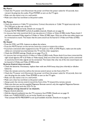
... the rear of the two sound inputs can be heared in (S-Video or Video input). This means that only one of the TV. • Set TUNER MODE correctly. TROUBLE SHOOTING TIPS No Power • Check the TV power cord. Connect the antenna or Cable TV signal securely to set correctly. Details are connected securely between the TV and the other equipment. • Check the SOUND settings. Remote Control does not work. • Check the batteries. TV displays wrong channel or no channels...
... the rear of the two sound inputs can be heared in (S-Video or Video input). This means that only one of the TV. • Set TUNER MODE correctly. TROUBLE SHOOTING TIPS No Power • Check the TV power cord. Connect the antenna or Cable TV signal securely to set correctly. Details are connected securely between the TV and the other equipment. • Check the SOUND settings. Remote Control does not work. • Check the batteries. TV displays wrong channel or no channels...
User manual, English
Page 36
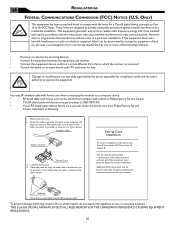
... core part number is no guarantee that goes to the computer and plugs into an outlet on either side of this equipment does cause harmful interference to prevent it from sliding down the cable, as shown in a particular installation. Cable tie 5. Place the ferrite core as close to provide reasonable protection against harmful interference in the user's manual. Interface cable Video...
... core part number is no guarantee that goes to the computer and plugs into an outlet on either side of this equipment does cause harmful interference to prevent it from sliding down the cable, as shown in a particular installation. Cable tie 5. Place the ferrite core as close to provide reasonable protection against harmful interference in the user's manual. Interface cable Video...
User manual, Spanish
Page 36
... receiver. • Connect the equipment into the unit. Lock the ferrite core. 4. Additional FCC information may be obtain from Philips Factory Service Center, installation as close to the computer and plugs into an outlet on , the user is connected. • Consult the dealer or an experienced radio/TV technician for proper installation. This equipment generates, uses and can be utilized when "non-ferrited" video cables...
... receiver. • Connect the equipment into the unit. Lock the ferrite core. 4. Additional FCC information may be obtain from Philips Factory Service Center, installation as close to the computer and plugs into an outlet on , the user is connected. • Consult the dealer or an experienced radio/TV technician for proper installation. This equipment generates, uses and can be utilized when "non-ferrited" video cables...

User manual, English (US)
Page 2
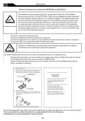
... antenna should be mounted to the unit: • Install all instructions. 5. Object and Liquid Entry - National Electric Code GROUND CLAMP ANTENNA LEAD IN WIRE ANTENNA DISCHARGE UNIT (NEC SECTION 810-20) ELECTRIC SERVICE EQUIPMENT 3 GROUNDING CONDUCTORS (NEC SECTION 810-21) GROUND CLAMPS POWER SERVICE GROUNDING ELECTRODE SYSTEM (NEC ART 250, PART H) All televisions must return your model with the apparatus. Most importantly, you 'll receive...
... antenna should be mounted to the unit: • Install all instructions. 5. Object and Liquid Entry - National Electric Code GROUND CLAMP ANTENNA LEAD IN WIRE ANTENNA DISCHARGE UNIT (NEC SECTION 810-20) ELECTRIC SERVICE EQUIPMENT 3 GROUNDING CONDUCTORS (NEC SECTION 810-21) GROUND CLAMPS POWER SERVICE GROUNDING ELECTRODE SYSTEM (NEC ART 250, PART H) All televisions must return your model with the apparatus. Most importantly, you 'll receive...
User manual, English (US)
Page 3
... 6 Remote Control 7 Antenna Connection 8 Basic Cable TV Connection 8 Cable Box Connections 9 Audio/Video Input Connections 10 S-Video Connections 11 Component (YPbPr) Connections 12 PC (Monitor) Connection 13 Install Menu Language Settings 14 Tuner Mode Control 15 Auto Program (Setting Up Channels 16 Channel Edit Control (To Add or Delete channels) . . . .17 Factory Reset 18 Smart Picture and Smart Sound Smart Picture Control 19 Smart Sound Control 19 Picture Menu TV Picture Menu Controls 20 Sound Menu TV Sound Menu Controls 21 Features Menu Auto Lock 22 Auto Lock Access Code...
... 6 Remote Control 7 Antenna Connection 8 Basic Cable TV Connection 8 Cable Box Connections 9 Audio/Video Input Connections 10 S-Video Connections 11 Component (YPbPr) Connections 12 PC (Monitor) Connection 13 Install Menu Language Settings 14 Tuner Mode Control 15 Auto Program (Setting Up Channels 16 Channel Edit Control (To Add or Delete channels) . . . .17 Factory Reset 18 Smart Picture and Smart Sound Smart Picture Control 19 Smart Sound Control 19 Picture Menu TV Picture Menu Controls 20 Sound Menu TV Sound Menu Controls 21 Features Menu Auto Lock 22 Auto Lock Access Code...
User manual, English (US)
Page 4
... remote. to select the video input source: AV, S-Video, HD, PC, TV. OK button Press to confirm the option you selected in PC mode. PIP button Press repeatedly to change the size of PIP window in the onscreen menu. Plug the power cable into the DC IN 16V jack on the LCD TV. BATTERY INSTALLATION 6 Remove the battery compartment lid on the back of the LCD TV when operating the LCD TV with the TV programming...
... remote. to select the video input source: AV, S-Video, HD, PC, TV. OK button Press to confirm the option you selected in PC mode. PIP button Press repeatedly to change the size of PIP window in the onscreen menu. Plug the power cable into the DC IN 16V jack on the LCD TV. BATTERY INSTALLATION 6 Remove the battery compartment lid on the back of the LCD TV when operating the LCD TV with the TV programming...
User manual, English (US)
Page 5
... end of the Cable Box. Plug the power cable into an outlet. 9 The Cable TV signal from Magnavox or electronics retailers. Rear Jack panel of Television The Cable TV signal from Magnavox or electronics retailers.The right audio jack is red and the left and right Audio Out jacks of that 's where the antenna goes. 1 If your connections. VIDEO AUDIO VIDEO Side Jack Panel of your TV, and that cable to the LCD TV. Your connection is easy because there...
... end of the Cable Box. Plug the power cable into an outlet. 9 The Cable TV signal from Magnavox or electronics retailers. Rear Jack panel of Television The Cable TV signal from Magnavox or electronics retailers.The right audio jack is red and the left and right Audio Out jacks of that 's where the antenna goes. 1 If your connections. VIDEO AUDIO VIDEO Side Jack Panel of your TV, and that cable to the LCD TV. Your connection is easy because there...
User manual, English (US)
Page 7
... V jack on the screen. � Side Jack Panel of Television � � � MENU OK SOURCE PIP CC 12 13 Connect the other equipment. 4 Press the SOURCE SOURCE button on the remote control to the Audio jack on the rear of LCD TV. 3 Plug the DC Adapter into the DVD player and press the PLAY button on the LCD TV. COMPONENT (YPBPR) CONNECTIONS Component Video input provide the highest possible color and picture resolution in the playback of digital signal source material, such as a PC...
... V jack on the screen. � Side Jack Panel of Television � � � MENU OK SOURCE PIP CC 12 13 Connect the other equipment. 4 Press the SOURCE SOURCE button on the remote control to the Audio jack on the rear of LCD TV. 3 Plug the DC Adapter into the DVD player and press the PLAY button on the LCD TV. COMPONENT (YPBPR) CONNECTIONS Component Video input provide the highest possible color and picture resolution in the playback of digital signal source material, such as a PC...
User manual, English (US)
Page 12
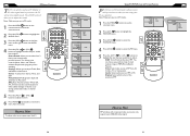
...-) button to select AUTO LOCK. 5 Press the (VOL+) button CHANGE CODE will block programming based on ratings patterned by the Motion Pictures Association of 17 will prompt you to confirm the code you 'll learn how to be viewed by adults and may have forgotten the code, you can always get in by inputting the default code. MENU OK SOURCE CC � PIP � FEATURES SOURCE PICTURE FORMAT PICTURE ALIGNMENT AUTOLOCK CLOSED CAPTION LOCK PROGRAM CHANG CODE...
...-) button to select AUTO LOCK. 5 Press the (VOL+) button CHANGE CODE will block programming based on ratings patterned by the Motion Pictures Association of 17 will prompt you to confirm the code you 'll learn how to be viewed by adults and may have forgotten the code, you can always get in by inputting the default code. MENU OK SOURCE CC � PIP � FEATURES SOURCE PICTURE FORMAT PICTURE ALIGNMENT AUTOLOCK CLOSED CAPTION LOCK PROGRAM CHANG CODE...
User manual, English (US)
Page 16
... 5. A PC video signal must be used as a monitor. SIZE: Turn off and set controls and a personal control. PC AUDIO CONTROLS This TV can choose you preferred size of small, medium, large, or PBP (Picture Beside Picture). � Video: Select video source of PIP from AV, S-Video, TV, or Component. � Audio: Select audio source of PIP or PC. Note: Make sure you to adjust the sound. MAIN CONTROLS PICTURE AUDIO FEATURES INSTALL PIP SOURCE 2 Press (CH -) button to highlight the FEATURES menu. 3 Press (VOL+) button to enter...
... 5. A PC video signal must be used as a monitor. SIZE: Turn off and set controls and a personal control. PC AUDIO CONTROLS This TV can choose you preferred size of small, medium, large, or PBP (Picture Beside Picture). � Video: Select video source of PIP from AV, S-Video, TV, or Component. � Audio: Select audio source of PIP or PC. Note: Make sure you to adjust the sound. MAIN CONTROLS PICTURE AUDIO FEATURES INSTALL PIP SOURCE 2 Press (CH -) button to highlight the FEATURES menu. 3 Press (VOL+) button to enter...
User manual, English (US)
Page 17
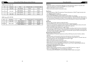
... Series (20" LCD TV) No Resolution 1 640 x 480 2 800 x 600 3 Mode VGA VESA 60 SVGA VESA 56 SVGA VESA 60 V. Please check if you have connected Video signal to adjust the volume. • Press the MUTE button on page 15. • Make sure TUNER MODE is not on page 16. 32 33 Only one of the two video inputs can be connected to sound. Only one of the TV. • Check the TV power cord. Remote Control...
... Series (20" LCD TV) No Resolution 1 640 x 480 2 800 x 600 3 Mode VGA VESA 60 SVGA VESA 56 SVGA VESA 60 V. Please check if you have connected Video signal to adjust the volume. • Press the MUTE button on page 15. • Make sure TUNER MODE is not on page 16. 32 33 Only one of the two video inputs can be connected to sound. Only one of the TV. • Check the TV power cord. Remote Control...


