Lenovo K4 Series User Guide V1.0
Page 39
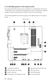
... illustrations show the locations of devices that are factory-installed or that you can install later. Lenovo K430 1 2 3 4 5 6 7 17 16 15 14 13 12 11 10 9 8 12V power connector Microprocessor fan header Power connector PCI express X 16 adapter slots (2) Microprocessor and heat sink Memory slots (4) Front USB header Power fan header 34 User Guide
... illustrations show the locations of devices that are factory-installed or that you can install later. Lenovo K430 1 2 3 4 5 6 7 17 16 15 14 13 12 11 10 9 8 12V power connector Microprocessor fan header Power connector PCI express X 16 adapter slots (2) Microprocessor and heat sink Memory slots (4) Front USB header Power fan header 34 User Guide
Lenovo K4 Series User Guide V1.0
Page 40
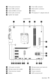
Front panel connector Front USB connector Serial (COM2) connector Front audio connector System fan header Front USB connector Mode switch connector Battery PCI express X 1 adapter slots (2) Lenovo K410 1 2 3 4 5 6 7 8 9 20 19 18 17 16 15 14 13 12V power connector Microprocessor fan header Thermal sensor header Battery 12 11 10 Microprocessor and heat sink Memory slots (2) Power connector SATA connectors (3) User Guide 35
Front panel connector Front USB connector Serial (COM2) connector Front audio connector System fan header Front USB connector Mode switch connector Battery PCI express X 1 adapter slots (2) Lenovo K410 1 2 3 4 5 6 7 8 9 20 19 18 17 16 15 14 13 12V power connector Microprocessor fan header Thermal sensor header Battery 12 11 10 Microprocessor and heat sink Memory slots (2) Power connector SATA connectors (3) User Guide 35
Lenovo K4 Series User Guide V1.0
Page 42
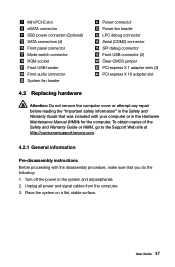
Unplug all peripherals. 2. Turn off the power to the Support Web site at http://consumersupport.lenovo.com. 4.2.1 General information Pre-disassembly instructions Before proceeding with the disassembly procedure, make sure that was included with your computer or in ... obtain copies of the Safety and Warranty Guide or HMM, go to the system and all power and signal cables from the computer. 3. Mini PCI-E slot eSATA connector SSD power connector (Optional) SATA connectors (4) Front panel connector Mode switch connector ROM socket Front USB header Front audio connector System fan ...
Unplug all peripherals. 2. Turn off the power to the Support Web site at http://consumersupport.lenovo.com. 4.2.1 General information Pre-disassembly instructions Before proceeding with the disassembly procedure, make sure that was included with your computer or in ... obtain copies of the Safety and Warranty Guide or HMM, go to the system and all power and signal cables from the computer. 3. Mini PCI-E slot eSATA connector SSD power connector (Optional) SATA connectors (4) Front panel connector Mode switch connector ROM socket Front USB header Front audio connector System fan ...


