Lenovo K4 Series User Guide V1.0
Page 7
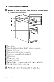
Power button Power Control Switch indicator ON/OFF (selected models only) Hard disk drive indicator Power control switch (selected models only) Memory card readers (selected models only) USB connector Microphone connector Headphone connector Optical drive (some models are equipped with only one optical drive) Hot plug HDD port (selected models only) Attention: Do not insert 3-inch discs into the optical drive. 2 User Guide 1.1 Front view of the chassis Attention: Be careful not to block any air vents on the computer. Blocked air vents can cause overheating.
Power button Power Control Switch indicator ON/OFF (selected models only) Hard disk drive indicator Power control switch (selected models only) Memory card readers (selected models only) USB connector Microphone connector Headphone connector Optical drive (some models are equipped with only one optical drive) Hot plug HDD port (selected models only) Attention: Do not insert 3-inch discs into the optical drive. 2 User Guide 1.1 Front view of the chassis Attention: Be careful not to block any air vents on the computer. Blocked air vents can cause overheating.
Lenovo K4 Series User Guide V1.0
Page 34
Chapter Hardware Replacement Guide This chapter contains the following topics: Identifying internal components Identifying parts on the system board Removing the computer cover Removing the front bezel Replacing a memory module Replacing a hard disk drive Replacing an optical drive Replacing a graphics card Replacing the TV-Tuner card Replacing the keyboard and mouse User Guide 29
Chapter Hardware Replacement Guide This chapter contains the following topics: Identifying internal components Identifying parts on the system board Removing the computer cover Removing the front bezel Replacing a memory module Replacing a hard disk drive Replacing an optical drive Replacing a graphics card Replacing the TV-Tuner card Replacing the keyboard and mouse User Guide 29
Lenovo K4 Series User Guide V1.0
Page 35
This guide does not include procedures for parts ordering information. This guide contains instructions for replacing the following parts: • Memory modules • Hard disk drive • Optical disk drive • Graphics card • TV-Tuner card Safety information for step-by-step...who are replacing Customer Replaceable Units (CRUs) as well as parts. The description of all parts. It is intended to be used by Lenovo®. Overview This guide is expected that was included with your computer or attempt any repairs before reading the "Important safety information" in ...
This guide does not include procedures for parts ordering information. This guide contains instructions for replacing the following parts: • Memory modules • Hard disk drive • Optical disk drive • Graphics card • TV-Tuner card Safety information for step-by-step...who are replacing Customer Replaceable Units (CRUs) as well as parts. The description of all parts. It is intended to be used by Lenovo®. Overview This guide is expected that was included with your computer or attempt any repairs before reading the "Important safety information" in ...

Lenovo K4 Series User Guide V1.0
Page 37
... or other unpainted metal surface on the computer for at least two seconds. When handling parts and other computer components with care, and handle adapters, memory modules, system boards, and microprocessors by their edges. If this is not possible, place the part on a smooth, flat surface before installing it directly into...
... or other unpainted metal surface on the computer for at least two seconds. When handling parts and other computer components with care, and handle adapters, memory modules, system boards, and microprocessors by their edges. If this is not possible, place the part on a smooth, flat surface before installing it directly into...
Lenovo K4 Series User Guide V1.0
Page 39
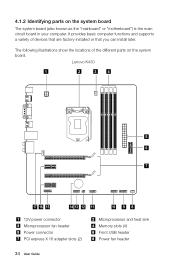
... of devices that are factory-installed or that you can install later. Lenovo K430 1 2 3 4 5 6 7 17 16 15 14 13 12 11 10 9 8 12V power connector Microprocessor fan header Power connector PCI express X 16 adapter slots (2) Microprocessor and heat sink Memory slots (4) Front USB header Power fan header 34 User Guide 4.1.2 Identifying parts...
... of devices that are factory-installed or that you can install later. Lenovo K430 1 2 3 4 5 6 7 17 16 15 14 13 12 11 10 9 8 12V power connector Microprocessor fan header Power connector PCI express X 16 adapter slots (2) Microprocessor and heat sink Memory slots (4) Front USB header Power fan header 34 User Guide 4.1.2 Identifying parts...
Lenovo K4 Series User Guide V1.0
Page 40
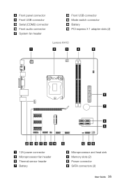
Front panel connector Front USB connector Serial (COM2) connector Front audio connector System fan header Front USB connector Mode switch connector Battery PCI express X 1 adapter slots (2) Lenovo K410 1 2 3 4 5 6 7 8 9 20 19 18 17 16 15 14 13 12V power connector Microprocessor fan header Thermal sensor header Battery 12 11 10 Microprocessor and heat sink Memory slots (2) Power connector SATA connectors (3) User Guide 35
Front panel connector Front USB connector Serial (COM2) connector Front audio connector System fan header Front USB connector Mode switch connector Battery PCI express X 1 adapter slots (2) Lenovo K410 1 2 3 4 5 6 7 8 9 20 19 18 17 16 15 14 13 12V power connector Microprocessor fan header Thermal sensor header Battery 12 11 10 Microprocessor and heat sink Memory slots (2) Power connector SATA connectors (3) User Guide 35
Lenovo K4 Series User Guide V1.0
Page 43
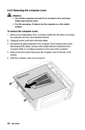
... computer. 4.2.2 Removing the computer cover Attention: • Turn off all attached devices. 2. This includes power cords, input/output (I/O) cables, and any media (disks, CDs, or memory cards) from electrical outlets. 3. To remove the computer cover: 1. Refer to "Locating connectors on a flat, stable surface. Unplug all power cords from the drives, shut...
... computer. 4.2.2 Removing the computer cover Attention: • Turn off all attached devices. 2. This includes power cords, input/output (I/O) cables, and any media (disks, CDs, or memory cards) from electrical outlets. 3. To remove the computer cover: 1. Refer to "Locating connectors on a flat, stable surface. Unplug all power cords from the drives, shut...
Lenovo K4 Series User Guide V1.0
Page 45
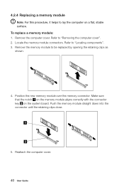
... straight down into the connector until the retaining clips close. 5. Position the new memory module over the memory connector. Refer to be replaced by opening the retaining clips as shown. 4. Remove the memory module to "Locating components". 3. 4.2.4 Replacing a memory module Note: For this procedure, it helps to "Removing the computer cover". 2. Reattach the computer...
... straight down into the connector until the retaining clips close. 5. Position the new memory module over the memory connector. Refer to be replaced by opening the retaining clips as shown. 4. Remove the memory module to "Locating components". 3. 4.2.4 Replacing a memory module Note: For this procedure, it helps to "Removing the computer cover". 2. Reattach the computer...
Lenovo K4 Series User Guide V1.0
Page 53
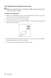
... Guide To replace the keyboard: 1. Locate the connector for the keyboard. Disconnect the defective keyboard cable from electrical outlets. 3. Remove any media (disks, CDs, or memory cards) from the drives, shut down the computer, and turn off all power cords from the computer and connect the new keyboard cable to "Front...
... Guide To replace the keyboard: 1. Locate the connector for the keyboard. Disconnect the defective keyboard cable from electrical outlets. 3. Remove any media (disks, CDs, or memory cards) from the drives, shut down the computer, and turn off all power cords from the computer and connect the new keyboard cable to "Front...


