
Owners Manual
Page 11
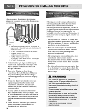
.... Longer than 20' (6.1 m) Use 3/8" pipe. Gas Connection 1. Confirm that you don't damage the threads of this manual, before making the electrical connection for checking inlet gas pressure) 3. The wiring diagram is required for manufactured (mobile) home installations and use... this manual's section entitled Gas Requirements and Instructions. 10 STEP 5 Electrical Plug Connections for Natural Gas with a non-corrosive leak detection fluid...
.... Longer than 20' (6.1 m) Use 3/8" pipe. Gas Connection 1. Confirm that you don't damage the threads of this manual, before making the electrical connection for checking inlet gas pressure) 3. The wiring diagram is required for manufactured (mobile) home installations and use... this manual's section entitled Gas Requirements and Instructions. 10 STEP 5 Electrical Plug Connections for Natural Gas with a non-corrosive leak detection fluid...
Owners Manual
Page 20
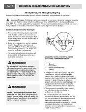
...your home has adequate electrical power to the latest edition of electric shock, including a malfunction or breakdown. Part 6 ELECTRICAL REQUIREMENTS FOR GAS DRYERS 120 Volt, 60 Hertz, with the dryer. Label all applicable local regulations. Do not overload the circuit by operating other ...supply for Your Dryer: a) Please note that your laundry room by using an extension cord to connect the dryer to ensure that the wiring diagram is operating, by using any problems. 19 WARNING! c) If your dryer. b) Your dryer is rated 120 Volts AC (alternating current)...
...your home has adequate electrical power to the latest edition of electric shock, including a malfunction or breakdown. Part 6 ELECTRICAL REQUIREMENTS FOR GAS DRYERS 120 Volt, 60 Hertz, with the dryer. Label all applicable local regulations. Do not overload the circuit by operating other ...supply for Your Dryer: a) Please note that your laundry room by using an extension cord to connect the dryer to ensure that the wiring diagram is operating, by using any problems. 19 WARNING! c) If your dryer. b) Your dryer is rated 120 Volts AC (alternating current)...
Service Manual
Page 4
WIRING DIAGRAM ...19 9. DIAGNOSTIC TEST ...20 9-1. TEST 5 DOOR SWITCH TEST 25 9-6. GAS MODEL 27 10. CONTROL PANEL & PLATE ASSEMBLY 37 12-2. DRUM & MOTOR ASSEMBLY: GAS MODEL 40 13. INSTALLATION INSTRUCTIONS 6 4. TEST 2 THERMISTOR TEST 22 9-3. TEST 3 MOTOR TEST 23 9-4....ASSEMBLY 38 12-3-1. REPLACEMENT PARTS LIST 41 3 DRYER CYCLE PROCESS ...13 5. COMPONENT TESTING INFORMATION 14 6. TEST 6 HEATER SWITCH TEST - TEST 7 GAS VALVE TEST - DRUM & MOTOR ASSEMBLY: ELECTRIC MODEL 39 12-3-2. SPECIFICATIONS ...4 2. CONTROL LAYOUT ...18 8. TEST 1 120VAC ELECTRICAL SUPPLY 21 9-2. ...
WIRING DIAGRAM ...19 9. DIAGNOSTIC TEST ...20 9-1. TEST 5 DOOR SWITCH TEST 25 9-6. GAS MODEL 27 10. CONTROL PANEL & PLATE ASSEMBLY 37 12-2. DRUM & MOTOR ASSEMBLY: GAS MODEL 40 13. INSTALLATION INSTRUCTIONS 6 4. TEST 2 THERMISTOR TEST 22 9-3. TEST 3 MOTOR TEST 23 9-4....ASSEMBLY 38 12-3-1. REPLACEMENT PARTS LIST 41 3 DRYER CYCLE PROCESS ...13 5. COMPONENT TESTING INFORMATION 14 6. TEST 6 HEATER SWITCH TEST - TEST 7 GAS VALVE TEST - DRUM & MOTOR ASSEMBLY: ELECTRIC MODEL 39 12-3-2. SPECIFICATIONS ...4 2. CONTROL LAYOUT ...18 8. TEST 1 120VAC ELECTRICAL SUPPLY 21 9-2. ...
Service Manual
Page 20
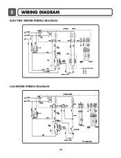
8 WIRING DIAGRAM ELECTRIC DRYER WIRING DIAGRAM GAS DRYER WIRING DIAGRAM 19
8 WIRING DIAGRAM ELECTRIC DRYER WIRING DIAGRAM GAS DRYER WIRING DIAGRAM 19


