
Owners Manual
Page 4
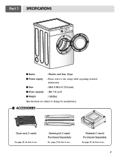
Stacking kit (1 each ) See page 26 for how to use. I Dryer capacity : IEC 7.0 cu.ft. I Power supply : Please refer to the rating label regarding detailed information. Pedestal (1 each) Purchased Separately See page 14 for how to use. 3 I Size : 68.6 X 96.5 X 73.0 (cm) I Weight : 126(Ibs) Specifications are subject to change by manufacturer. Part 1 SPECIFICATIONS I Name : Electric and Gas Dryer I ACCESSORIES Dryer rack (1 each ) Purchased Separately See page 13 for how to use.
Stacking kit (1 each ) See page 26 for how to use. I Dryer capacity : IEC 7.0 cu.ft. I Power supply : Please refer to the rating label regarding detailed information. Pedestal (1 each) Purchased Separately See page 14 for how to use. 3 I Size : 68.6 X 96.5 X 73.0 (cm) I Weight : 126(Ibs) Specifications are subject to change by manufacturer. Part 1 SPECIFICATIONS I Name : Electric and Gas Dryer I ACCESSORIES Dryer rack (1 each ) Purchased Separately See page 13 for how to use.
Owners Manual
Page 5
...Use the space below to other than private family use, all warranty coverage is printed the end of Purchase ❈ Staple your new LG dryer. Date of this dryer is available by contacting your safety, the recommendations in material or workmanship. ! You will repair or replace...on the front of purchase, if this manual. Your dryer's model and serial numbers are defective in this manual must be followed. Part 2 IMPORTANT WARRANTY AND SAFETY INSTRUCTIONS SEEKING WARRANTY ASSISTANCE Warranty Service. The warranty for your dryer is effective for warranty period from the ...
...Use the space below to other than private family use, all warranty coverage is printed the end of Purchase ❈ Staple your new LG dryer. Date of this dryer is available by contacting your safety, the recommendations in material or workmanship. ! You will repair or replace...on the front of purchase, if this manual. Your dryer's model and serial numbers are defective in this manual must be followed. Part 2 IMPORTANT WARRANTY AND SAFETY INSTRUCTIONS SEEKING WARRANTY ASSISTANCE Warranty Service. The warranty for your dryer is effective for warranty period from the ...
Owners Manual
Page 6
... must be connected to a grounded metal, permanent wiring system or an equipment-grounding conductor must be run with controls. 8) Do not repair or replace any part of the appliance or attempt any risk of electric shock, fire, or other flammable or explosive substances, as to the equipment-grounding terminal or lead... other personal or property injury when using the appliance. 2) Do not dry articles that have come into the appliance if the drum is properly grounded. Part 2 IMPORTANT WARRANTY AND SAFETY INSTRUCTIONS IMPORTANT SAFETY INSTRUCTIONS !
... must be connected to a grounded metal, permanent wiring system or an equipment-grounding conductor must be run with controls. 8) Do not repair or replace any part of the appliance or attempt any risk of electric shock, fire, or other flammable or explosive substances, as to the equipment-grounding terminal or lead... other personal or property injury when using the appliance. 2) Do not dry articles that have come into the appliance if the drum is properly grounded. Part 2 IMPORTANT WARRANTY AND SAFETY INSTRUCTIONS IMPORTANT SAFETY INSTRUCTIONS !
Owners Manual
Page 7
... TO DO IF YOU SMELL GAS: • Do not try to four of all occupants. • Immediately call your gas supplier, call the fire department. ! Part 2 IMPORTANT WARRANTY AND SAFETY INSTRUCTIONS ! WARNING To reduce the risk of natural gas or LP fuels. Follow the gas supplier's instructions carefully. • If you...
... TO DO IF YOU SMELL GAS: • Do not try to four of all occupants. • Immediately call your gas supplier, call the fire department. ! Part 2 IMPORTANT WARRANTY AND SAFETY INSTRUCTIONS ! WARNING To reduce the risk of natural gas or LP fuels. Follow the gas supplier's instructions carefully. • If you...
Owners Manual
Page 8
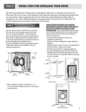
... floor for your dryer, and it any installation or use. Choose a location with elbow. A louvered door with any closer of other parts of this manual. STEP 1 Positioning the Dryer. Place the dryer at other recessed area. Please also keep the following information and manual...please confirm that every section of this entire manual before proceeding with comparable ventilation openings are set forth in the picture below. Part 3 INITIAL STEPS FOR INSTALLING YOUR DRYER The following instructions will help guide you through reference to the following instructions in mind when...
... floor for your dryer, and it any installation or use. Choose a location with elbow. A louvered door with any closer of other parts of this manual. STEP 1 Positioning the Dryer. Place the dryer at other recessed area. Please also keep the following information and manual...please confirm that every section of this entire manual before proceeding with comparable ventilation openings are set forth in the picture below. Part 3 INITIAL STEPS FOR INSTALLING YOUR DRYER The following instructions will help guide you through reference to the following instructions in mind when...

Owners Manual
Page 9
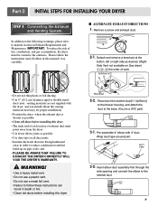
... sensors may malfunction. The maximum slope of the dryer from left to right or from front to back. SSTTEEPP 22: Procedure for your door opens: 1 2 3 8 Part 3 INITIAL STEPS FOR INSTALLING YOUR DRYER Once in which your dryer. Follow these procedures to back should not rock.
... sensors may malfunction. The maximum slope of the dryer from left to right or from front to back. SSTTEEPP 22: Procedure for your door opens: 1 2 3 8 Part 3 INITIAL STEPS FOR INSTALLING YOUR DRYER Once in which your dryer. Follow these procedures to back should not rock.
Owners Manual
Page 10
..., and you should obtain the venting materials necessary for proper installation) • Position the dryer where the exhaust duct is a SVC part) 3-1. Insert elbow duct assembly first through unheated areas in death or fire. • Clean old ducts before installing this dryer 2-2. ... FAILURE TO EXHAUST THE DRYER CORRECTLY WILL VOID THE DRYER'S WARRANTY. ! Remove a screw and exhaust duct. 2-1. Wrap duct tape around joint. 3-2. Part 3 INITIAL STEPS FOR INSTALLING YOUR DRYER STEP 3 Connecting the Exhaust and Venting System. WARNING! • Use a heavy metal vent. • Do...
..., and you should obtain the venting materials necessary for proper installation) • Position the dryer where the exhaust duct is a SVC part) 3-1. Insert elbow duct assembly first through unheated areas in death or fire. • Clean old ducts before installing this dryer 2-2. ... FAILURE TO EXHAUST THE DRYER CORRECTLY WILL VOID THE DRYER'S WARRANTY. ! Remove a screw and exhaust duct. 2-1. Wrap duct tape around joint. 3-2. Part 3 INITIAL STEPS FOR INSTALLING YOUR DRYER STEP 3 Connecting the Exhaust and Venting System. WARNING! • Use a heavy metal vent. • Do...
Owners Manual
Page 11
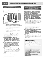
... is provided at the back of gas available in a clothes dryer. 2. Use only a new U.L. Iron Pipe. The dryer is provided inside the dryer control hood. Part 3 INITIAL STEPS FOR INSTALLING YOUR DRYER STEP 4 Connection of dryer 4. In addition to the following, please refer to this manual's section on Gas Requirements and...
... is provided at the back of gas available in a clothes dryer. 2. Use only a new U.L. Iron Pipe. The dryer is provided inside the dryer control hood. Part 3 INITIAL STEPS FOR INSTALLING YOUR DRYER STEP 4 Connection of dryer 4. In addition to the following, please refer to this manual's section on Gas Requirements and...
Owners Manual
Page 12
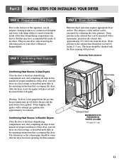
..., as described more fully in this manual for proper installation of this dryer, start the dryer on your dryer after approximately two minutes. Part 3 INITIAL STEPS FOR INSTALLING YOUR DRYER STEP 6 Preparation of the airflow can be measured with a manometer, placed on the exhaust duct approximately...minutes. After the dryer starts, the igniter will glow red and the main burner will re-attempt gas ignition after reviewing the following parts on a heat setting, as described more fully in your dryer's Electrical Requirements. The exhaust air or the exhaust pipe should not ...
..., as described more fully in this manual for proper installation of this dryer, start the dryer on your dryer after approximately two minutes. Part 3 INITIAL STEPS FOR INSTALLING YOUR DRYER STEP 6 Preparation of the airflow can be measured with a manometer, placed on the exhaust duct approximately...minutes. After the dryer starts, the igniter will glow red and the main burner will re-attempt gas ignition after reviewing the following parts on a heat setting, as described more fully in your dryer's Electrical Requirements. The exhaust air or the exhaust pipe should not ...
Owners Manual
Page 13
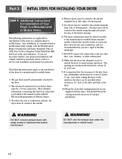
...exhaust ducts with the dryer. WARNING! More detailed information concerning the electrical connection is recommended that extend into the duct. ! WARNING! Part 3 INITIAL STEPS FOR INSTALLING YOUR DRYER STEP 9 Additional Instructions for Installation of Your Dryer in a manufactured or mobile home must comply... with the Manufactured Home Construction and Safety Standards Title 24 CFR, Part 32-80 or Standard CAN/CSA0Z240 MH and local codes and ordinances. The following instructions are uncertain whether your proposed installation ...
...exhaust ducts with the dryer. WARNING! More detailed information concerning the electrical connection is recommended that extend into the duct. ! WARNING! Part 3 INITIAL STEPS FOR INSTALLING YOUR DRYER STEP 9 Additional Instructions for Installation of Your Dryer in a manufactured or mobile home must comply... with the Manufactured Home Construction and Safety Standards Title 24 CFR, Part 32-80 or Standard CAN/CSA0Z240 MH and local codes and ordinances. The following instructions are uncertain whether your proposed installation ...
Owners Manual
Page 14
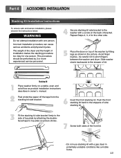
... side of top plate by 2 or more experienced service personnel. 4 Secure stacking kit side bracket to the stopper of bracket. Repeat Steps 2, 3, 4 for one person. Part 4 ACESSORIES INSTALLATION Stacking Kit Installation Instructions To ensure safe and secure installation, please observe the instructions below. WARNING Do not attempt installation with a screw on...
... side of top plate by 2 or more experienced service personnel. 4 Secure stacking kit side bracket to the stopper of bracket. Repeat Steps 2, 3, 4 for one person. Part 4 ACESSORIES INSTALLATION Stacking Kit Installation Instructions To ensure safe and secure installation, please observe the instructions below. WARNING Do not attempt installation with a screw on...
Owners Manual
Page 16
... fused on next page. wire (copper wire only), or as required by local codes. Sample methods are included in dryers which to local code requirements. Part 5 ELECTRICAL REQUIREMENTS FOR ELECTRIC DRYERS Following are available for field installation in the following pages. Please contact a qualified electrician to check your home's wiring and...
... fused on next page. wire (copper wire only), or as required by local codes. Sample methods are included in dryers which to local code requirements. Part 5 ELECTRICAL REQUIREMENTS FOR ELECTRIC DRYERS Following are available for field installation in the following pages. Please contact a qualified electrician to check your home's wiring and...

Owners Manual
Page 17
... 1. Make ends of power cord to center terminal block screw. 2. Make sure that all terminal block nuts are on tight and power cord is tightened. Part 5 ELECTRICAL REQUIREMENTS FOR ELECTRIC DRYERS Review the following options to determine the appropriate electrical connection for dryer to be replaced.
... 1. Make ends of power cord to center terminal block screw. 2. Make sure that all terminal block nuts are on tight and power cord is tightened. Part 5 ELECTRICAL REQUIREMENTS FOR ELECTRIC DRYERS Review the following options to determine the appropriate electrical connection for dryer to be replaced.

Owners Manual
Page 18
... wire under the screw of covering material from end and bare 1 inch from the ends. Connect red and black wire to center terminal block screw. 2. Part 5 ELECTRICAL REQUIREMENTS FOR ELECTRIC DRYERS 3-wire connection : Direct wire Important : use a 4wire connection. and be replaced. Connect ground wire(green) of power cord to external...
... wire under the screw of covering material from end and bare 1 inch from the ends. Connect red and black wire to center terminal block screw. 2. Part 5 ELECTRICAL REQUIREMENTS FOR ELECTRIC DRYERS 3-wire connection : Direct wire Important : use a 4wire connection. and be replaced. Connect ground wire(green) of power cord to external...

Owners Manual
Page 19
Part 5 ELECTRICAL REQUIREMENTS FOR ELECTRIC DRYERS Option 2: 3-Wire Connection with a Power Supply Cord lf your local codes or ordinances permit the connection of power cord to ...
Part 5 ELECTRICAL REQUIREMENTS FOR ELECTRIC DRYERS Option 2: 3-Wire Connection with a Power Supply Cord lf your local codes or ordinances permit the connection of power cord to ...
Owners Manual
Page 20
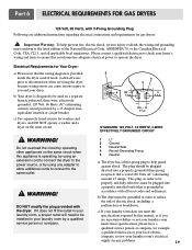
.... ! This plug, in order to help prevent fire, electric shock, serious injury or death, the wiring and grounding must be used on the same circuit. ! Part 6 ELECTRICAL REQUIREMENTS FOR GAS DRYERS 120 Volt, 60 Hertz, with 3-Prong Grounding Plug Following are uncertain whether or not your laundry room meets these specifications...
.... ! This plug, in order to help prevent fire, electric shock, serious injury or death, the wiring and grounding must be used on the same circuit. ! Part 6 ELECTRICAL REQUIREMENTS FOR GAS DRYERS 120 Volt, 60 Hertz, with 3-Prong Grounding Plug Following are uncertain whether or not your laundry room meets these specifications...
Owners Manual
Page 21
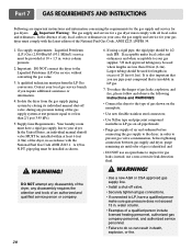
... Requirements. To reduce the danger of an authorized and qualified service person or company. 6. It is also important that you require additional assistance or information. 4. Part 7 GAS REQUIREMENTS AND INSTRUCTIONS Following are less than 2/1 psi (3.45 kPa). 5. In the absence of any disassembly requires the attention and tools of gas leaks...
... Requirements. To reduce the danger of an authorized and qualified service person or company. 6. It is also important that you require additional assistance or information. 4. Part 7 GAS REQUIREMENTS AND INSTRUCTIONS Following are less than 2/1 psi (3.45 kPa). 5. In the absence of any disassembly requires the attention and tools of gas leaks...
Owners Manual
Page 22
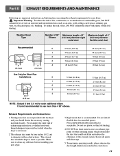
... is not in diameter with plastic or thin foil ducting. Rigid metal duct is acceptable. Do not install flexible duct in the chart above. 21 Part 8 EXHAUST REQUIREMENTS AND MAINTENANCE Following are not provided with duct tape. 5. Secure all joints with the dryer and you should be four inches (10.2 cm...
... is not in diameter with plastic or thin foil ducting. Rigid metal duct is acceptable. Do not install flexible duct in the chart above. 21 Part 8 EXHAUST REQUIREMENTS AND MAINTENANCE Following are not provided with duct tape. 5. Secure all joints with the dryer and you should be four inches (10.2 cm...
Owners Manual
Page 23
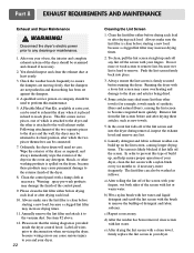
... after drying each load. 10. Clean the control panel with hot or warm water. The lint filter can also be connected. 7. c) Repeat as new towels. 5. Part 8 EXHAUST REQUIREMENTS AND MAINTENANCE Exhaust and Dryer Maintenance ! Disconnect the dryer's electric power prior to ensure the dampers are moving freely, that the dampers are...
... after drying each load. 10. Clean the control panel with hot or warm water. The lint filter can also be connected. 7. c) Repeat as new towels. 5. Part 8 EXHAUST REQUIREMENTS AND MAINTENANCE Exhaust and Dryer Maintenance ! Disconnect the dryer's electric power prior to ensure the dampers are moving freely, that the dampers are...
Owners Manual
Page 24
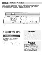
... Sensor Dry Cycles or Manual Cycles will show in minutes) will glow. Explosion Hazard Keep flammable materials and vapors, such as gasoline, away from dryer. Part 9 OPERATING YOUR DRYER Following are instructions for starting and using an Air Cycle.
... Sensor Dry Cycles or Manual Cycles will show in minutes) will glow. Explosion Hazard Keep flammable materials and vapors, such as gasoline, away from dryer. Part 9 OPERATING YOUR DRYER Following are instructions for starting and using an Air Cycle.


