
Owners Manual
Page 3
... ...13-14 PART5. EXHAUST REQUIREMENTS AND MAINTENANCE 21-22 PART9. ELECTRICAL REQUIREMENTS FOR ELECTRIC DRYER 15-18 PART6. TROUBLESHOOTING GUIDE ...29-31 LG DRYER LIMITED WARRANTY ...32 2 TABLE OF CONTENTS PART1. ELECTRICAL REQUIREMENTS FOR GAS DRYERS 19 PART7. OPERATING YOUR DRYER...23-28 PART10. PRODUCT... to mention unmatched big capacity, you can benefit from good time efficiency, quiet operation and energy saving system. 2 DOUBLE-COATED STEEL DRUM It is coated with one metal coating and the other polymer coating in order to guarantee high durability and the long life. 3...
... ...13-14 PART5. EXHAUST REQUIREMENTS AND MAINTENANCE 21-22 PART9. ELECTRICAL REQUIREMENTS FOR ELECTRIC DRYER 15-18 PART6. TROUBLESHOOTING GUIDE ...29-31 LG DRYER LIMITED WARRANTY ...32 2 TABLE OF CONTENTS PART1. ELECTRICAL REQUIREMENTS FOR GAS DRYERS 19 PART7. OPERATING YOUR DRYER...23-28 PART10. PRODUCT... to mention unmatched big capacity, you can benefit from good time efficiency, quiet operation and energy saving system. 2 DOUBLE-COATED STEEL DRUM It is coated with one metal coating and the other polymer coating in order to guarantee high durability and the long life. 3...
Owners Manual
Page 6
... or lead on or in doubt as they give off vapors that is properly grounded. The plug must be plugged into the appliance if the drum is moving. 6) Do not install or store this appliance where it will not fit the outlet, have come into contact with a qualified electrician or service...
... or lead on or in doubt as they give off vapors that is properly grounded. The plug must be plugged into the appliance if the drum is moving. 6) Do not install or store this appliance where it will not fit the outlet, have come into contact with a qualified electrician or service...
Owners Manual
Page 12
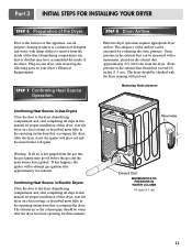
...allpurpose cleaning products or a solution of detergent and water, with damp clothes to the dryer drum/drying compartment and, after completing all steps in Electric Dryers Close the door to the dryer drum/drying compartment and, after approximately two minutes. Confirming Heat Source in this manual for proper ...will glow red and the main burner will re-attempt gas ignition after completing all air is not purged from the inside of the dryer drum/drying compartment any dust or dirt that accompany the dryer. The exhaust air or the exhaust pipe should not exceed 0.6 inches (1.5 cm...
...allpurpose cleaning products or a solution of detergent and water, with damp clothes to the dryer drum/drying compartment and, after completing all steps in Electric Dryers Close the door to the dryer drum/drying compartment and, after approximately two minutes. Confirming Heat Source in this manual for proper ...will glow red and the main burner will re-attempt gas ignition after completing all air is not purged from the inside of the dryer drum/drying compartment any dust or dirt that accompany the dryer. The exhaust air or the exhaust pipe should not exceed 0.6 inches (1.5 cm...
Owners Manual
Page 23
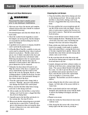
... dryer, because these articles, such as follows: a) After rolling the lint off the screen with a loose lint screen may shed more quickly. Ordinarily, the dryer drum will need no care. Wipe the exterior of the dryer as required, and always immediately wipe the exterior of the dryer in the event any...
... dryer, because these articles, such as follows: a) After rolling the lint off the screen with a loose lint screen may shed more quickly. Ordinarily, the dryer drum will need no care. Wipe the exterior of the dryer as required, and always immediately wipe the exterior of the dryer in the event any...
Owners Manual
Page 28
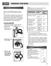
... Dry temperature setting. Use RACK DRY to flow in your dryer. Make sure that is indicated. The RACK DRY is evenly placed right onto the drum inside the dryer to select the desired time. Refer to the following table. • Start the dryer. 10. Beeper The BEEPER controls the volume of... tumble dry, including sweaters and similar items. The heated dryer rack allows the heated air inside and door rim. Put the dryer rack into the drum 3. Low/Ultra 20/30 Low Air Dry/ 50/30 Ultra Low Foam rubber pillows Air Dry 50 Athletic shoes Air Dry 20 * Reset time as...
... Dry temperature setting. Use RACK DRY to flow in your dryer. Make sure that is indicated. The RACK DRY is evenly placed right onto the drum inside the dryer to select the desired time. Refer to the following table. • Start the dryer. 10. Beeper The BEEPER controls the volume of... tumble dry, including sweaters and similar items. The heated dryer rack allows the heated air inside and door rim. Put the dryer rack into the drum 3. Low/Ultra 20/30 Low Air Dry/ 50/30 Ultra Low Foam rubber pillows Air Dry 50 Athletic shoes Air Dry 20 * Reset time as...
Owners Manual
Page 30
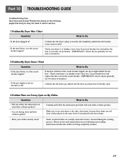
Confirm and follow the instructions on My Clothes Question What to Do • Is the dryer plugged in the dryer drum. • Were your fabric softener product. • Are you drying clean and dirty clothes together? Make sure to use two fuses or breakers.) • Is ...
Confirm and follow the instructions on My Clothes Question What to Do • Is the dryer plugged in the dryer drum. • Were your fabric softener product. • Are you drying clean and dirty clothes together? Make sure to use two fuses or breakers.) • Is ...
Service Manual
Page 4
... MODEL 26 9-7. TEST 7 GAS VALVE TEST - EXPLODED VIEW ...37 12-1. CONTROL PANEL & PLATE ASSEMBLY 37 12-2. REPLACEMENT PARTS LIST 41 3 DRUM & MOTOR ASSEMBLY: GAS MODEL 40 13. WIRING DIAGRAM ...19 9. TEST 1 120VAC ELECTRICAL SUPPLY 21 9-2. TEST 5 DOOR SWITCH TEST 25... 9-6. DRUM & MOTOR ASSEMBLY: ELECTRIC MODEL 39 12-3-2. MOTOR DIAGRAM AND SCHEMATIC 17 7. TEST 2 THERMISTOR TEST 22 9-3. DISASSEMBLY INSTRUCTIONS 30 12. TEST...
... MODEL 26 9-7. TEST 7 GAS VALVE TEST - EXPLODED VIEW ...37 12-1. CONTROL PANEL & PLATE ASSEMBLY 37 12-2. REPLACEMENT PARTS LIST 41 3 DRUM & MOTOR ASSEMBLY: GAS MODEL 40 13. WIRING DIAGRAM ...19 9. TEST 1 120VAC ELECTRICAL SUPPLY 21 9-2. TEST 5 DOOR SWITCH TEST 25... 9-6. DRUM & MOTOR ASSEMBLY: ELECTRIC MODEL 39 12-3-2. MOTOR DIAGRAM AND SCHEMATIC 17 7. TEST 2 THERMISTOR TEST 22 9-3. DISASSEMBLY INSTRUCTIONS 30 12. TEST...
Service Manual
Page 6
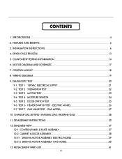
of Programs 5 No. of Temperature Controls 5 No. ITEM Material & Finish Color Top Plate Door Trim DLE2512W DLG2522W TD-V10062G DLE2514W DLG2524W Blue White Painted Silver Blue White DLE2515S DLG2525S Titaium Chrom REMARK POWER SUPPLY 120V/240V 60Hz (26A) ELECTRICITY ... (22.5A) 15 W (125mA) AC 120V AC 240V (ELECTRIC MODEL) AC 120V GAS VALVE CONTROL TYPE 13 W (110mA) x 2 Electronic AC 120V (GAS MODEL) DRUM CAPACITY 7.0 cu.ft. Net/Gross 124/144 No. of Dry Options 3 No. Weight (lbs) - of Dry Levels 3 Sound levels High/Low/Off Sensor Moisture Temperature...
of Programs 5 No. of Temperature Controls 5 No. ITEM Material & Finish Color Top Plate Door Trim DLE2512W DLG2522W TD-V10062G DLE2514W DLG2524W Blue White Painted Silver Blue White DLE2515S DLG2525S Titaium Chrom REMARK POWER SUPPLY 120V/240V 60Hz (26A) ELECTRICITY ... (22.5A) 15 W (125mA) AC 120V AC 240V (ELECTRIC MODEL) AC 120V GAS VALVE CONTROL TYPE 13 W (110mA) x 2 Electronic AC 120V (GAS MODEL) DRUM CAPACITY 7.0 cu.ft. Net/Gross 124/144 No. of Dry Options 3 No. Weight (lbs) - of Dry Levels 3 Sound levels High/Low/Off Sensor Moisture Temperature...
Service Manual
Page 7
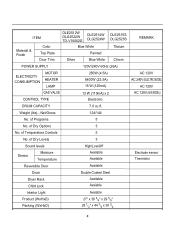
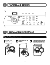
Hold the dryer rack with both hands. 2 Put the dryer rack into the drum 3 Check and be sure that the front of the rack is properly seated behind the lint filter. 6 2 FEATURES AND BENEFITS 3 INSTALLATION INSTRUCTIONS Dryer Rack Installation Instructions 1Open the door.
Hold the dryer rack with both hands. 2 Put the dryer rack into the drum 3 Check and be sure that the front of the rack is properly seated behind the lint filter. 6 2 FEATURES AND BENEFITS 3 INSTALLATION INSTRUCTIONS Dryer Rack Installation Instructions 1Open the door.

Service Manual
Page 21
... must be used for Factory test /Service test. Current Temp. (5 ~ 70) ELECTRIC TYPE: Heater runs GAS TYPE: GAS Valve runs (Display the Temperature of Inside drum.) Gas valve See test 7 4 times Control Off During check, Motor & Heater Off + Lamp On + If the door is open the door. This TEST should be...
... must be used for Factory test /Service test. Current Temp. (5 ~ 70) ELECTRIC TYPE: Heater runs GAS TYPE: GAS Valve runs (Display the Temperature of Inside drum.) Gas valve See test 7 4 times Control Off During check, Motor & Heater Off + Lamp On + If the door is open the door. This TEST should be...
Service Manual
Page 24
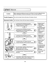
...check) • Check Controller connector. • Replace Outlet • Thermostat. (Refer to 'Component') • Check Idler Assembly. • Drum Belt cuts off • Drum Belt takes off , and do voltage discharge. (When discharging, contact the metal plug of Outlet Thermostat attached to 'Motor Diagram & Check') &#...measure resistance. NO YES Is resistance below 3Ω between terminals of Power cord with earth line.) Trouble Symptom Drum will not rotate; No Heater will function; Test 3 Motor test Caution Before measuring resistance, be sure to Motor Bracket operate Level...
...check) • Check Controller connector. • Replace Outlet • Thermostat. (Refer to 'Component') • Check Idler Assembly. • Drum Belt cuts off • Drum Belt takes off , and do voltage discharge. (When discharging, contact the metal plug of Outlet Thermostat attached to 'Motor Diagram & Check') &#...measure resistance. NO YES Is resistance below 3Ω between terminals of Power cord with earth line.) Trouble Symptom Drum will not rotate; No Heater will function; Test 3 Motor test Caution Before measuring resistance, be sure to Motor Bracket operate Level...
Service Manual
Page 26
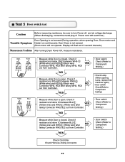
Door Close is not sensed. (Drum motor will flash at 0.5 second intervals.) Measurement Condition After turning Dryer Power Off, measure resistance. Check if resistance is below 1Ω between WH3- (White wire) ...(Yellow wire) and WH3- (White wire) after taking Connector WH3, BL2 out from Controller. Measure while Door is not sensed.(During operation, when opening Door, Drum motor and Trouble Symptom Heater run continuously; Check if resistance is open . Check Harness-linking connector. 25 YES NO Measure while Door is below 1Ω...
Door Close is not sensed. (Drum motor will flash at 0.5 second intervals.) Measurement Condition After turning Dryer Power Off, measure resistance. Check if resistance is below 1Ω between WH3- (White wire) ...(Yellow wire) and WH3- (White wire) after taking Connector WH3, BL2 out from Controller. Measure while Door is not sensed.(During operation, when opening Door, Drum motor and Trouble Symptom Heater run continuously; Check if resistance is open . Check Harness-linking connector. 25 YES NO Measure while Door is below 1Ω...

Service Manual
Page 34
...Replace the lamp shield and screw. 33 Disconnect the door lamp and electrode sensor connector. 4. Remove the Cabinet Cover and Tub drum [front]. 3. CHANGING THE DRUM LAMP 1. WARNING ! Disassemble the top plate. 2. Loosen belt from motor and idler pulleys. 4. Remove the bulb and ...so can cause serious injury. 1. Remove 4 screws. 5. Disassemble the Tub Drum [Front]. 1. Remove Cover Cabinet. 3. Slide the shield up and remove. 4. TUB DRUM [FRONT] DRUM ASSEMBLY -1 -1 -2 ! Carefully remove the drum. Hold the lamp shield in place while removing the screw. 3. Failure to...
...Replace the lamp shield and screw. 33 Disconnect the door lamp and electrode sensor connector. 4. Remove the Cabinet Cover and Tub drum [front]. 3. CHANGING THE DRUM LAMP 1. WARNING ! Disassemble the top plate. 2. Loosen belt from motor and idler pulleys. 4. Remove the bulb and ...so can cause serious injury. 1. Remove 4 screws. 5. Disassemble the Tub Drum [Front]. 1. Remove Cover Cabinet. 3. Slide the shield up and remove. 4. TUB DRUM [FRONT] DRUM ASSEMBLY -1 -1 -2 ! Carefully remove the drum. Hold the lamp shield in place while removing the screw. 3. Failure to...

Service Manual
Page 36
Disconnect the electrode sensor. 1. Remove 2 screws and cover (Air guide). 5. Remove the Back Cover. 35 Remove the Drum assembly. 4. Remove the Cover Grid. 4. Disconnect the motor clamp and motor. 1. Remove 7 screws. 5. Disassemble the top plate. 2. Remove the Cabinet Cover and Tub Drum [Front]. 3. Disassemble the top plate. 2. Remove 3 screws. 3. Remove the fan. 7. Remove the filter. 2. Remove the bolt and washer. 6. Remove the Cabinet Cover and Tub Drum [Front]. 3. 1. Remove the Drum assembly. 4.
Disconnect the electrode sensor. 1. Remove 2 screws and cover (Air guide). 5. Remove the Back Cover. 35 Remove the Drum assembly. 4. Remove the Cover Grid. 4. Disconnect the motor clamp and motor. 1. Remove 7 screws. 5. Disassemble the top plate. 2. Remove the Cabinet Cover and Tub Drum [Front]. 3. Disassemble the top plate. 2. Remove 3 screws. 3. Remove the fan. 7. Remove the filter. 2. Remove the bolt and washer. 6. Remove the Cabinet Cover and Tub Drum [Front]. 3. 1. Remove the Drum assembly. 4.
Service Manual
Page 37
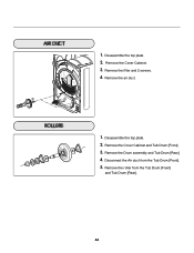
Disassemble the top plate. 2. Remove the roller from the Tub Drum [Front]. 5. Disassemble the top plate. 2. Remove the Cover Cabinet. 3. Remove the air duct. 1. Disconnect the Air duct from the Tub Drum [Front] and Tub Drum [Rear]. 36 Remove the Drum assembly and Tub Drum [Rear]. 4. Remove the Cover Cabinet and Tub Drum [Front]. 3. Remove the filter and 2 screws. 4. 1.
Disassemble the top plate. 2. Remove the roller from the Tub Drum [Front]. 5. Disassemble the top plate. 2. Remove the Cover Cabinet. 3. Remove the air duct. 1. Disconnect the Air duct from the Tub Drum [Front] and Tub Drum [Rear]. 36 Remove the Drum assembly and Tub Drum [Rear]. 4. Remove the Cover Cabinet and Tub Drum [Front]. 3. Remove the filter and 2 screws. 4. 1.
Service Manual
Page 40
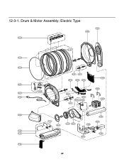
Drum & Motor Assembly: Electric Type F200 K400 K120 K100 K130 K221 K230 K210 K350 K140 K250 K251 K330 K320 K340 K250 K251 K360 K550 K560 K310 K620 K610 K240 F130 F110 F120 F140 K540 K510 K520 K530 K651 K640 K600 K650 39 12-3-1.
Drum & Motor Assembly: Electric Type F200 K400 K120 K100 K130 K221 K230 K210 K350 K140 K250 K251 K330 K320 K340 K250 K251 K360 K550 K560 K310 K620 K610 K240 F130 F110 F120 F140 K540 K510 K520 K530 K651 K640 K600 K650 39 12-3-1.


