

Owner's Manual
Page 1
ENGLISH LCD TV PLASMA TV OWNER'S MANUAL LCD TV MODELS 26LC4* 32LC4* 37LC4* 42LC4* 26LC3* 26LC5* 32LC5* 37LC5* 42LC5* PLASMA TV MODELS 42PC5* 42PC5RV* 50PC5* Please read this information to your set . Retain it for future reference. Record model number and serial number of the set . See the label attached on the back cover and quote this manual carefully before operating your dealer when you require service.
ENGLISH LCD TV PLASMA TV OWNER'S MANUAL LCD TV MODELS 26LC4* 32LC4* 37LC4* 42LC4* 26LC3* 26LC5* 32LC5* 37LC5* 42LC5* PLASMA TV MODELS 42PC5* 42PC5RV* 50PC5* Please read this information to your set . Retain it for future reference. Record model number and serial number of the set . See the label attached on the back cover and quote this manual carefully before operating your dealer when you require service.
Owner's Manual
Page 3
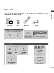
... only Cable Management 26LC3R* only Cable Management 1 INDEX 9 FAV Owner's Manual Batteries Remote Control Power Cord Plasma TV models This feature is not available for all models. 2- PIP PIP PR+ SIZE TV DVD VCR EXIT LIST PIP POSTION INPUT MENU I/II OK SLEEP VOL Q.VIEW 1 MUTE PR 4 2 7 5... 3 * 8 6 TIME 0 REVEAL ? ARC INPUTTINVPUT POWER PIP TEXT PR- TV Brackets 2- ACCESSORIES ACCESSORIES Ensure that excessive power may cause scratch or discoloration. If an accessory is stain or fingerprint on the exterior only ...
... only Cable Management 26LC3R* only Cable Management 1 INDEX 9 FAV Owner's Manual Batteries Remote Control Power Cord Plasma TV models This feature is not available for all models. 2- PIP PIP PR+ SIZE TV DVD VCR EXIT LIST PIP POSTION INPUT MENU I/II OK SLEEP VOL Q.VIEW 1 MUTE PR 4 2 7 5... 3 * 8 6 TIME 0 REVEAL ? ARC INPUTTINVPUT POWER PIP TEXT PR- TV Brackets 2- ACCESSORIES ACCESSORIES Ensure that excessive power may cause scratch or discoloration. If an accessory is stain or fingerprint on the exterior only ...

Owner's Manual
Page 4
Colour Tone - Picture Improvement Technology 52 Demo 53 Advanced - User Mode 61 Balance 62 TV Speakers On/Off Setup 63 I/II - NICAM Reception 65 - Screen Setup for Wire Arrangement 10 Desktop Pedestal Installation 12 Wall...ACCESSORIES 1 PREPARATION Front Panel Controls 4 Back Panel Information 6 Stand Installation 8 Attaching the TV to a Wall 9 Back Cover for PC Mode 28 WATCHIINNGGTTVV//PROGRAMMMMEECCOONNTTRROOLL Remote Control Key Functions 32 Turning on the TV 34 Programme Selection 34 Volume Adjustment 34 On Screen Menu Selection and Adjustment ..........35 Auto ...
Colour Tone - Picture Improvement Technology 52 Demo 53 Advanced - User Mode 61 Balance 62 TV Speakers On/Off Setup 63 I/II - NICAM Reception 65 - Screen Setup for Wire Arrangement 10 Desktop Pedestal Installation 12 Wall...ACCESSORIES 1 PREPARATION Front Panel Controls 4 Back Panel Information 6 Stand Installation 8 Attaching the TV to a Wall 9 Back Cover for PC Mode 28 WATCHIINNGGTTVV//PROGRAMMMMEECCOONNTTRROOLL Remote Control Key Functions 32 Turning on the TV 34 Programme Selection 34 Volume Adjustment 34 On Screen Menu Selection and Adjustment ..........35 Auto ...

Owner's Manual
Page 6
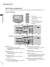
VOL PR POWER Button INPUT Button MENU Button OK Button VOLUME Buttons PROGRAMME Buttons 4 Plasma TV Models PREPARATION INPUT MENU OK VOL PR INPUT MENU OK INPUT VOLMENU OK PR Remote Control Sensor Power/Standby Indicator • illuminates red in... standby mode. • illuminates green when the set is a simplified representation of the front panel. PREPARATION FRONT PANEL CONTROLS I If your TV. I This is switched on. Here shown may be somewhat different from your product has a protection film attached, remove the film and then wipe the product...
VOL PR POWER Button INPUT Button MENU Button OK Button VOLUME Buttons PROGRAMME Buttons 4 Plasma TV Models PREPARATION INPUT MENU OK VOL PR INPUT MENU OK INPUT VOLMENU OK PR Remote Control Sensor Power/Standby Indicator • illuminates red in... standby mode. • illuminates green when the set is a simplified representation of the front panel. PREPARATION FRONT PANEL CONTROLS I If your TV. I This is switched on. Here shown may be somewhat different from your product has a protection film attached, remove the film and then wipe the product...

Owner's Manual
Page 7
LCD TV Models 26LC4*, 32LC4*, 37LC4*, 42LC4*, 26LC5*, 32LC5*, 37LC5*, 42LC5* PREPARATION R Remote Control Sensor Power/Standby Indicator • illuminates red in standby mode. • illuminates green when the set is switched on. 26LC3R* PR VOL OK MENU INPUT /I PROGRAMME Buttons VOLUME Buttons OK Button MENU Button INPUT Button POWER Button R Remote Control Sensor Power/Standby Indicator • illuminates red in standby mode. • illuminates green when the set is switched on. 5
LCD TV Models 26LC4*, 32LC4*, 37LC4*, 42LC4*, 26LC5*, 32LC5*, 37LC5*, 42LC5* PREPARATION R Remote Control Sensor Power/Standby Indicator • illuminates red in standby mode. • illuminates green when the set is switched on. 26LC3R* PR VOL OK MENU INPUT /I PROGRAMME Buttons VOLUME Buttons OK Button MENU Button INPUT Button POWER Button R Remote Control Sensor Power/Standby Indicator • illuminates red in standby mode. • illuminates green when the set is switched on. 5
Owner's Manual
Page 8
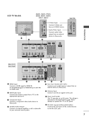
...2 RGB/Audio Input Connect the monitor output from an external device to these jacks. 6 Antenna Input Connect over-the-air signals to operate the TV on the Specifications page. Here shown may be somewhat different from your surround sound system. 8 5 6 5 Euro Scart Socket (AV1/AV2) ... PREPARATION BACK PANEL INFORMATION I This is indicated on DC power. 8 RS-232C Input(CONTROL&SERVICE)Port Connect the serial port of the back panel. Plasma TV Models AV IN 3 VIDEO L/MONO AUDIO R S-VIDEO VIDEO L/MONO AUDIO R S-VIDEO VIDEO L/MONO AUDIO R S-VIDEO AV IN 3 AV IN 3 7 1 2 HDMI/DVI...
...2 RGB/Audio Input Connect the monitor output from an external device to these jacks. 6 Antenna Input Connect over-the-air signals to operate the TV on the Specifications page. Here shown may be somewhat different from your surround sound system. 8 5 6 5 Euro Scart Socket (AV1/AV2) ... PREPARATION BACK PANEL INFORMATION I This is indicated on DC power. 8 RS-232C Input(CONTROL&SERVICE)Port Connect the serial port of the back panel. Plasma TV Models AV IN 3 VIDEO L/MONO AUDIO R S-VIDEO VIDEO L/MONO AUDIO R S-VIDEO VIDEO L/MONO AUDIO R S-VIDEO AV IN 3 AV IN 3 7 1 2 HDMI/DVI...
Owner's Manual
Page 9
...audio/video output from an external device to these jacks. 6 Antenna Input Connect over-the-air signals to this jack. 7 Power Cord Socket This TV operates on the Specifications page. VIDEO AUDIO RGB INCOMPONENT IN AVAVUADRI1IOABOHLUEDT MIH/AD1DVVMI II2N/D1VI IN HDMI IHNDMI IN 22 ANTENNA IN RGB INRGB IN... surround sound system. 8 5 6 5 Euro Scart Socket (AV1/AV2) Connect scart socket input or output from an S-VIDEO device. Never attempt to operate the TV on DC power. 8 RS-232C Input(CONTROL&SERVICE)Port Connect the serial port of the control devices to HDMI IN. PREPARATION LCD...
...audio/video output from an external device to these jacks. 6 Antenna Input Connect over-the-air signals to this jack. 7 Power Cord Socket This TV operates on the Specifications page. VIDEO AUDIO RGB INCOMPONENT IN AVAVUADRI1IOABOHLUEDT MIH/AD1DVVMI II2N/D1VI IN HDMI IHNDMI IN 22 ANTENNA IN RGB INRGB IN... surround sound system. 8 5 6 5 Euro Scart Socket (AV1/AV2) Connect scart socket input or output from an S-VIDEO device. Never attempt to operate the TV on DC power. 8 RS-232C Input(CONTROL&SERVICE)Port Connect the serial port of the control devices to HDMI IN. PREPARATION LCD...

Owner's Manual
Page 10
PREPARATION PREPARATION STAND INSTALLATION (Only 26, 32, 37 inch LCD TV models) 1 Carefully place the product screen side down on a cushioned surface that will protect product and screen from damage. 2 Assemble the product stand with the product as shown. 3 Install the 4 bolts securely, in the back of the product in the holes provided. 8
PREPARATION PREPARATION STAND INSTALLATION (Only 26, 32, 37 inch LCD TV models) 1 Carefully place the product screen side down on a cushioned surface that will protect product and screen from damage. 2 Assemble the product stand with the product as shown. 3 Install the 4 bolts securely, in the back of the product in the holes provided. 8

Owner's Manual
Page 11
...the bracket that is mounted on the wall. G Use a product holder or a cabinet that the height of the product. Plasma TV models LCD TV models 1 1 2 2 1 Use the eye-bolts or TV brackets/bolts to fix the product to another place undo the ropes first. Match the height of the product. 9 Please make... and strong enough for all models. G To use the product safely make sure that is mounted on or hang from the product. PREPARATION ATTACHING THE TV TO A WALL I Set it up the product, which is to tie the rope so it becomes horizontal between the wall and the product. ! I ...
...the bracket that is mounted on the wall. G Use a product holder or a cabinet that the height of the product. Plasma TV models LCD TV models 1 1 2 2 1 Use the eye-bolts or TV brackets/bolts to fix the product to another place undo the ropes first. Match the height of the product. 9 Please make... and strong enough for all models. G To use the product safely make sure that is mounted on or hang from the product. PREPARATION ATTACHING THE TV TO A WALL I Set it up the product, which is to tie the rope so it becomes horizontal between the wall and the product. ! I ...
Owner's Manual
Page 12
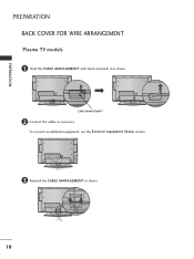
PREPARATION PREPARATION BACK COVER FOR WIRE ARRANGEMENT Plasma TV models 1 Hold the CABLE MANAGEMENT with hands and push it as shown. 10 To connect an additional equipment, see the External equipment Setup section. 3 Reinstall the CABLE MANAGEMENT as shown. CABLE MANAGEMENT 2 Connect the cables as necessary.
PREPARATION PREPARATION BACK COVER FOR WIRE ARRANGEMENT Plasma TV models 1 Hold the CABLE MANAGEMENT with hands and push it as shown. 10 To connect an additional equipment, see the External equipment Setup section. 3 Reinstall the CABLE MANAGEMENT as shown. CABLE MANAGEMENT 2 Connect the cables as necessary.
Owner's Manual
Page 13
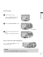
If the product is not available for all models.) CABLE MANAGEMENT How to remove the cable management Hold the CABLE MANAGEMENT with both hands and pull it upward. ! To connect an additional equipment, see the External equipment Setup section. 2 Install the CABLE MANAGEMENT as necessary. PREPARATION LCD TV models 1 Connect the cables as shown. 3 Bundle the cables using the supplied twister holder. (This feature is dropped, you may be injured or the product may be broken. 11 NOTE G Do not hold the CABLE MANAGEMENT when moving the product. -
If the product is not available for all models.) CABLE MANAGEMENT How to remove the cable management Hold the CABLE MANAGEMENT with both hands and pull it upward. ! To connect an additional equipment, see the External equipment Setup section. 2 Install the CABLE MANAGEMENT as necessary. PREPARATION LCD TV models 1 Connect the cables as shown. 3 Bundle the cables using the supplied twister holder. (This feature is dropped, you may be injured or the product may be broken. 11 NOTE G Do not hold the CABLE MANAGEMENT when moving the product. -

Owner's Manual
Page 14
..., lightening rods, or gas pipes. Do not try to ground the unit by connecting it to prevent possible electric shock. I The TV can be mounted horizontally. If grounding methods are not possible, have a qualified electrician install a separate circuit breaker. DESKTOP PEDESTAL INSTALLATION For... proper ventilation, allow a clearance of 4inches on a desktop etc. PREPARATION PREPARATION I The TV is designed to be installed in various ways such as on a wall, or on each side from the wall. 4 inches 4 inches 4 inches...
..., lightening rods, or gas pipes. Do not try to ground the unit by connecting it to prevent possible electric shock. I The TV can be mounted horizontally. If grounding methods are not possible, have a qualified electrician install a separate circuit breaker. DESKTOP PEDESTAL INSTALLATION For... proper ventilation, allow a clearance of 4inches on a desktop etc. PREPARATION PREPARATION I The TV is designed to be installed in various ways such as on a wall, or on each side from the wall. 4 inches 4 inches 4 inches...
Owner's Manual
Page 16
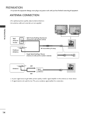
... signal areas,to get better VpIDiEcOture qualitAyUD,IOinstall aVAsRigIAnBaLlEamplifier to the antenna as shown above. PREPARATION PREPARATION I If signal needs to be split for two TVs,use an antenna signal splitter for connection. 14 COMPONENT IN AUDIO OUT I To prevent the equipment damage, never plug in any power cords until you...
... signal areas,to get better VpIDiEcOture qualitAyUD,IOinstall aVAsRigIAnBaLlEamplifier to the antenna as shown above. PREPARATION PREPARATION I If signal needs to be split for two TVs,use an antenna signal splitter for connection. 14 COMPONENT IN AUDIO OUT I To prevent the equipment damage, never plug in any power cords until you...
Owner's Manual
Page 17
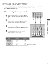
... Component input source with using the INPUT button on the set. 2 Connect the audio output of EXTERNAL EQUIPMENT SETUP mainly use pictures for the LCD TV models. EXTERNAL EQUIPMENT SETUP EXTERNAL EQUIPMENT SETUP I This part of the digital set-top box to the COMPONENT IN AUDIO jacks on the set. 1 2 3 Turn...
... Component input source with using the INPUT button on the set. 2 Connect the audio output of EXTERNAL EQUIPMENT SETUP mainly use pictures for the LCD TV models. EXTERNAL EQUIPMENT SETUP EXTERNAL EQUIPMENT SETUP I This part of the digital set-top box to the COMPONENT IN AUDIO jacks on the set. 1 2 3 Turn...
Owner's Manual
Page 18
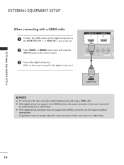
... digital set-top box player does not support Auto HDMI, you need to the owner's manual for the digital set the output resolution appropriately. NOTE G TV can receive the video and audio signal simultaneously with using a HDMI cable.
... digital set-top box player does not support Auto HDMI, you need to the owner's manual for the digital set the output resolution appropriately. NOTE G TV can receive the video and audio signal simultaneously with using a HDMI cable.
Owner's Manual
Page 20
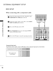
... quality, connect a DVD player to the COMPO- NENT IN AUDIO jacks on DVD player Y PB PR Y B-Y R-Y Y Cb Cr Y Pb Pr 18 Component ports on the TV Y PB PR Video output ports on the set . 2 Connect the audio outputs of the DVD to the component input ports as shown below.
... quality, connect a DVD player to the COMPO- NENT IN AUDIO jacks on DVD player Y PB PR Y B-Y R-Y Y Cb Cr Y Pb Pr 18 Component ports on the TV Y PB PR Video output ports on the set . 2 Connect the audio outputs of the DVD to the component input ports as shown below.
Owner's Manual
Page 22
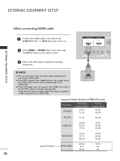
... will be automatically set to 1280x720p. G If the DVD player does not support Auto HDMI, you need to set the DVD output resolution appropriately. NOTE G TV can receive the video and audio signal simultaneously with using a HDMI cable. VIDEO L/MONO AUDIO R EXTERNAL EQUIPMENT SETUP AV IN 3 When connecting HDMI cable 1 Connect...
... will be automatically set to 1280x720p. G If the DVD player does not support Auto HDMI, you need to set the DVD output resolution appropriately. NOTE G TV can receive the video and audio signal simultaneously with using a HDMI cable. VIDEO L/MONO AUDIO R EXTERNAL EQUIPMENT SETUP AV IN 3 When connecting HDMI cable 1 Connect...
Owner's Manual
Page 23
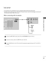
... IN socket of the screen may remain visible on the VCR and match the appropriate programme between the VCR and TV. I To avoid picture noise (interference), leave an adequate distance between the TV and VCR for viewing. 21 If the 4:3 picture format is used; EXTERNAL EQUIPMENT SETUP VCR SETUP I Typically a frozen still...
... IN socket of the screen may remain visible on the VCR and match the appropriate programme between the VCR and TV. I To avoid picture noise (interference), leave an adequate distance between the TV and VCR for viewing. 21 If the 4:3 picture format is used; EXTERNAL EQUIPMENT SETUP VCR SETUP I Typically a frozen still...
Owner's Manual
Page 25
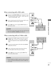
... on the remote control. AV IN 3 1 S-VIDEO VIDEO L R ANT IN OUTPUT SWITCH ANT OUT When connecting with a RCA cable 1 Connect the AUDIO/VIDEO jacks between TV and VCR. Match the jack colours (Video = yellow, Audio Left = white, and Audio Right = red) S-VIDEO VIDEO L/MONO AUDIO R 2 Insert a video tape into the VCR...
... on the remote control. AV IN 3 1 S-VIDEO VIDEO L R ANT IN OUTPUT SWITCH ANT OUT When connecting with a RCA cable 1 Connect the AUDIO/VIDEO jacks between TV and VCR. Match the jack colours (Video = yellow, Audio Left = white, and Audio Right = red) S-VIDEO VIDEO L/MONO AUDIO R 2 Insert a video tape into the VCR...

Owner's Manual
Page 26
Refer to external equipment operating guide. 24 Match the jack colours. (Video = yellow, Audio Left = white, and Audio Right = red) 2 Select AV3 input source with using the INPUT button on the remote control. 3 Operate the corresponding external equipment. EXTERNAL EQUIPMENT SETUP EXTERNAL EQUIPMENT SETUP OTHER A/V SOURCE SETUP Camcorder Video Game Set VIDEO L/MONO AUDIO R S-VIDEO AV IN 3 VIDEO L R 1 1 Connect the AUDIO/VIDEO jacks between TV and external equipment.
Refer to external equipment operating guide. 24 Match the jack colours. (Video = yellow, Audio Left = white, and Audio Right = red) 2 Select AV3 input source with using the INPUT button on the remote control. 3 Operate the corresponding external equipment. EXTERNAL EQUIPMENT SETUP EXTERNAL EQUIPMENT SETUP OTHER A/V SOURCE SETUP Camcorder Video Game Set VIDEO L/MONO AUDIO R S-VIDEO AV IN 3 VIDEO L R 1 1 Connect the AUDIO/VIDEO jacks between TV and external equipment.


