Product Guide
Page 3
... Guide is not intended for Intel® Desktop Board DP55KG. Use Only for other PC or embedded non-PC applications or other hardware components 3 Updating the BIOS: instructions on how to important information. may not be supported without further evaluation by Intel. The suitability of product features 2 Installing and Replacing Desktop Board Components: instructions on how to update the BIOS 4 Configuring for RAID Using Intel® Matrix Storage Technology: information about configuring your system for RAID A Error...
... Guide is not intended for Intel® Desktop Board DP55KG. Use Only for other PC or embedded non-PC applications or other hardware components 3 Updating the BIOS: instructions on how to important information. may not be supported without further evaluation by Intel. The suitability of product features 2 Installing and Replacing Desktop Board Components: instructions on how to update the BIOS 4 Configuring for RAID Using Intel® Matrix Storage Technology: information about configuring your system for RAID A Error...
Product Guide
Page 5
... 11 Desktop Board Components 12 Processor ...14 Main Memory...15 Intel® P55 Express Chipset 16 Audio Subsystem 16 LAN Subsystem 16 Bluetooth* Technology Support 17 USB 2.0 Support 17 Serial ATA Support 18 Legacy I/O ...19 Expandability...19 BIOS ...20 Serial ATA Auto Configuration 20 PCI* and PCI Express* Auto Configuration 20 Security Passwords 20 Hardware Management 21 Hardware Monitoring and Fan Speed Control 21 Intel® Precision Cooling Technology 21 Chassis Intrusion 21 Power Management 22 Software Support 22 ACPI 22 Hardware Support 22 Power Connectors 22 Fan...
... 11 Desktop Board Components 12 Processor ...14 Main Memory...15 Intel® P55 Express Chipset 16 Audio Subsystem 16 LAN Subsystem 16 Bluetooth* Technology Support 17 USB 2.0 Support 17 Serial ATA Support 18 Legacy I/O ...19 Expandability...19 BIOS ...20 Serial ATA Auto Configuration 20 PCI* and PCI Express* Auto Configuration 20 Security Passwords 20 Hardware Management 21 Hardware Monitoring and Fan Speed Control 21 Intel® Precision Cooling Technology 21 Chassis Intrusion 21 Power Management 22 Software Support 22 ACPI 22 Hardware Support 22 Power Connectors 22 Fan...
Product Guide
Page 6
... Removing a PCI Express x16 Graphics Card 47 Installing Linked PCI Express Graphics Cards 47 Connecting the Serial ATA (SATA) Cables 49 Connecting to the Internal Headers 50 S/PDIF Header 51 Front Panel Intel HD Audio Header 51 Consumer IR (CIR) Headers 51 Front Panel Header 52 Alternate Front Panel Power LED Header 53 USB 2.0 Headers 53 IEEE 1394a Header 54 Chassis Intrusion Header 54 Connecting to the Audio System 55 Connecting Chassis Fan and Power Supply Cables 56 Connecting Chassis Fan Cables 56 Connecting Power Supply Cables 57 Connecting the Bluetooth Antenna 58 Setting...
... Removing a PCI Express x16 Graphics Card 47 Installing Linked PCI Express Graphics Cards 47 Connecting the Serial ATA (SATA) Cables 49 Connecting to the Internal Headers 50 S/PDIF Header 51 Front Panel Intel HD Audio Header 51 Consumer IR (CIR) Headers 51 Front Panel Header 52 Alternate Front Panel Power LED Header 53 USB 2.0 Headers 53 IEEE 1394a Header 54 Chassis Intrusion Header 54 Connecting to the Audio System 55 Connecting Chassis Fan and Power Supply Cables 56 Connecting Chassis Fan Cables 56 Connecting Power Supply Cables 57 Connecting the Bluetooth Antenna 58 Setting...
Product Guide
Page 7
... Dual Channel Memory Configuration with Three DIMMs 42 21. Remove the Socket Cover 37 13. Installing a PCI Express x16 Graphics Card 46 24. Installing Linked PCI Express Graphics Cards 48 26. Onboard Power Button 26 6. Lower the Load Plate 39 16. Unlatch the Socket Lever 35 11. Install the Processor 38 15. Lift the Load Plate 36 12. Connecting the Processor Fan Heat Sink Power Cable to BIOS Button 28 8. Connecting the Serial ATA Cables 49 27. Example Dual Channel Memory Configuration with Two DIMMs 41 19. Intel Desktop Board DP55KG Components...
... Dual Channel Memory Configuration with Three DIMMs 42 21. Remove the Socket Cover 37 13. Installing a PCI Express x16 Graphics Card 46 24. Installing Linked PCI Express Graphics Cards 48 26. Onboard Power Button 26 6. Lower the Load Plate 39 16. Unlatch the Socket Lever 35 11. Install the Processor 38 15. Lift the Load Plate 36 12. Connecting the Processor Fan Heat Sink Power Cable to BIOS Button 28 8. Connecting the Serial ATA Cables 49 27. Example Dual Channel Memory Configuration with Two DIMMs 41 19. Intel Desktop Board DP55KG Components...
Product Guide
Page 8
.... Intel Desktop Board DP55KG China RoHS Material Self Declaration Table 87 Tables 1. LAN Connector LEDs 17 4. IEEE 1394a Header Signal Names 54 12. Port 80h POST Codes 76 18. Product Certification Markings 90 viii Connecting the Bluetooth Antenna 58 32. Front Panel Header Signal Names 52 9. USB 2.0 Header Signal Names 53 11. BIOS Error Messages 74 17. BIOS Beep Codes 73 15. Location of the BIOS Configuration Jumper Block 59 33. Connecting Power Supply Cables 57 31. Front Panel Intel HD Audio Header...
.... Intel Desktop Board DP55KG China RoHS Material Self Declaration Table 87 Tables 1. LAN Connector LEDs 17 4. IEEE 1394a Header Signal Names 54 12. Port 80h POST Codes 76 18. Product Certification Markings 90 viii Connecting the Bluetooth Antenna 58 32. Front Panel Header Signal Names 52 9. USB 2.0 Header Signal Names 53 11. BIOS Error Messages 74 17. BIOS Beep Codes 73 15. Location of the BIOS Configuration Jumper Block 59 33. Connecting Power Supply Cables 57 31. Front Panel Intel HD Audio Header...
Product Guide
Page 9
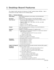
... memory • Support for an Intel® processor in the LGA1156 package • Four 240-pin DDR3 SDRAM Dual Inline Memory Module (DIMM) sockets arranged in optical connectors • One PCI Express 2.0 x16 port • One PCI Express 2.0 x8 port • One PCI Express 2.0 x4 port • Two PCI Express 2.0 x1 ports • Two PCI* bus connectors Legacy I/O Support Peripheral Interfaces Legacy I/O Controller that provides Consumer Infrared (CIR) support • Up to 13 USB 2.0 ports: ― Eight ports routed to eight back panel USB connectors...
... memory • Support for an Intel® processor in the LGA1156 package • Four 240-pin DDR3 SDRAM Dual Inline Memory Module (DIMM) sockets arranged in optical connectors • One PCI Express 2.0 x16 port • One PCI Express 2.0 x8 port • One PCI Express 2.0 x4 port • Two PCI Express 2.0 x1 ports • Two PCI* bus connectors Legacy I/O Support Peripheral Interfaces Legacy I/O Controller that provides Consumer Infrared (CIR) support • Up to 13 USB 2.0 ports: ― Eight ports routed to eight back panel USB connectors...
Product Guide
Page 10
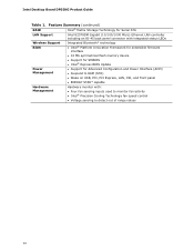
... Desktop Board DP55KG Product Guide Table 1. Feature Summary (continued) RAID Intel® Matrix Storage Technology for Serial ATA LAN Support Intel 82578DM Gigabit (10/100/1000 Mb/s) Ethernet LAN controller including an RJ-45 back panel connector with integrated status LEDs Wireless Support BIOS Integrated Bluetooth* technology • Intel® Platform Innovation Framework for extensible firmware interface • 16 Mb symmetrical flash memory device • Support for SMBIOS • Intel® Express BIOS Update Power Management • Support for Advanced Configuration...
... Desktop Board DP55KG Product Guide Table 1. Feature Summary (continued) RAID Intel® Matrix Storage Technology for Serial ATA LAN Support Intel 82578DM Gigabit (10/100/1000 Mb/s) Ethernet LAN controller including an RJ-45 back panel connector with integrated status LEDs Wireless Support BIOS Integrated Bluetooth* technology • Intel® Platform Innovation Framework for extensible firmware interface • 16 Mb symmetrical flash memory device • Support for SMBIOS • Intel® Express BIOS Update Power Management • Support for Advanced Configuration...
Product Guide
Page 13
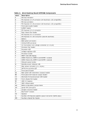
... header Processor LED Voltage regulator LED Processor socket POST code LED display DDR3 Channel A, DIMM 0 and DIMM 1 sockets DDR3 Channel B, DIMM 0 and DIMM 1 sockets Onboard power button Standby power indicator LED Main power connector (2 x 12 pin) SATA drive activity LED Front panel header Back panel CIR transmitter (output) header Front panel CIR receiver (input) header Alternate front panel power LED header Front chassis fan header USB 2.0 headers IEEE 1394a header BIOS configuration jumper block Serial ATA connectors Chassis intrusion header BlueTooth* module Speaker Auxiliary PCI Express...
... header Processor LED Voltage regulator LED Processor socket POST code LED display DDR3 Channel A, DIMM 0 and DIMM 1 sockets DDR3 Channel B, DIMM 0 and DIMM 1 sockets Onboard power button Standby power indicator LED Main power connector (2 x 12 pin) SATA drive activity LED Front panel header Back panel CIR transmitter (output) header Front panel CIR receiver (input) header Alternate front panel power LED header Front chassis fan header USB 2.0 headers IEEE 1394a header BIOS configuration jumper block Serial ATA connectors Chassis intrusion header BlueTooth* module Speaker Auxiliary PCI Express...
Product Guide
Page 19
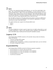
... F6 key to install the RAID drivers. The red eSATA connectors on each of the eSATA ports. x16 compatible) • One PCI Express 2.0 x4 port (x4 electrical; Desktop Board Features NOTE In order to use supported onboard RAID features, you must first enable RAID in the BIOS. Legacy I/O Intel Desktop Board DP55KG includes an I/O controller that provides the following legacy I/O features: • Consumer Infrared (CIR) support • Low pin count (LPC) interface • Intelligent power management, including a programmable wake up...
... F6 key to install the RAID drivers. The red eSATA connectors on each of the eSATA ports. x16 compatible) • One PCI Express 2.0 x4 port (x4 electrical; Desktop Board Features NOTE In order to use supported onboard RAID features, you must first enable RAID in the BIOS. Legacy I/O Intel Desktop Board DP55KG includes an I/O controller that provides the following legacy I/O features: • Consumer Infrared (CIR) support • Low pin count (LPC) interface • Intelligent power management, including a programmable wake up...
Product Guide
Page 20
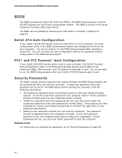
... for a password. Related Links: For instructions on page 67. You can be accessed and who can boot the computer. Serial ATA Auto Configuration If you install a PCI/PCI Express add-in the Serial Peripheral Interface (SPI) Flash device. The password prompt is displayed before the computer is stored in card. Intel Desktop Board DP55KG Product Guide BIOS The BIOS provides the Power-On Self-Test (POST), the BIOS Setup program, and the PCI/PCI Express and SATA auto-configuration utilities. The BIOS can override the auto-configuration options by...
... for a password. Related Links: For instructions on page 67. You can be accessed and who can boot the computer. Serial ATA Auto Configuration If you install a PCI/PCI Express add-in the Serial Peripheral Interface (SPI) Flash device. The password prompt is displayed before the computer is stored in card. Intel Desktop Board DP55KG Product Guide BIOS The BIOS provides the Power-On Self-Test (POST), the BIOS Setup program, and the PCI/PCI Express and SATA auto-configuration utilities. The BIOS can override the auto-configuration options by...
Product Guide
Page 22
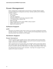
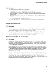
... Advanced Configuration and Power Interface (ACPI) and the following hardware support: • Power connectors • Fan headers • LAN wake capabilities • Instantly Available PC technology (Suspend to RAM) • +5 V standby power indicator LED • Wake from USB • Power Management Event signal (PME#) wakeup support • WAKE# signal wake-up support • Wake from an AC power failure, the computer returns to the power state it was in the BIOS Setup program's Boot menu. The Desktop Board has three power connectors. Intel Desktop Board DP55KG Product Guide Power...
... Advanced Configuration and Power Interface (ACPI) and the following hardware support: • Power connectors • Fan headers • LAN wake capabilities • Instantly Available PC technology (Suspend to RAM) • +5 V standby power indicator LED • Wake from USB • Power Management Event signal (PME#) wakeup support • WAKE# signal wake-up support • Wake from an AC power failure, the computer returns to the power state it was in the BIOS Setup program's Boot menu. The Desktop Board has three power connectors. Intel Desktop Board DP55KG Product Guide Power...
Product Guide
Page 23
..., it asserts a wake-up signal that can adjust the fan speed or switch the fan on the front panel, the sleep state is wired to provide adequate standby current when using this feature can damage the power supply and/or effect ACPI S3 sleep state functionality. The Desktop Board has a 4-pin processor fan header and three 4-pin chassis fan headers. While in memory. When signaled by the LED turning amber. Instantly Available PC technology enables the board to provide...
..., it asserts a wake-up signal that can adjust the fan speed or switch the fan on the front panel, the sleep state is wired to provide adequate standby current when using this feature can damage the power supply and/or effect ACPI S3 sleep state functionality. The Desktop Board has a 4-pin processor fan header and three 4-pin chassis fan headers. While in memory. When signaled by the LED turning amber. Instantly Available PC technology enables the board to provide...
Product Guide
Page 31
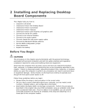
... of the computer chassis. 31 2 Installing and Replacing Desktop Board Components This chapter tells you how to: • Install the I/O shield • Install and remove the Desktop Board • Install and remove a processor • Install and remove memory • Install and remove a PCI Express x16 graphics card • Connect the Serial ATA cables • Connect to the internal headers • Connect to a metal part of the procedures described in personal injury or equipment damage. Failure to disconnect power, telecommunications links, networks, or modems...
... of the computer chassis. 31 2 Installing and Replacing Desktop Board Components This chapter tells you how to: • Install the I/O shield • Install and remove the Desktop Board • Install and remove a processor • Install and remove memory • Install and remove a PCI Express x16 graphics card • Connect the Serial ATA cables • Connect to the internal headers • Connect to a metal part of the procedures described in personal injury or equipment damage. Failure to disconnect power, telecommunications links, networks, or modems...
Product Guide
Page 47
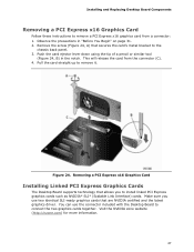
... NVIDIA* SLI* (Scalable Link Interface) cards. Removing a PCI Express x16 Graphics Card Installing Linked PCI Express Graphics Cards The Desktop Board supports technology that secures the card's metal bracket to the chassis back panel. 3. Observe the precautions in the notch. Figure 24. Installing and Replacing Desktop Board Components Removing a PCI Express x16 Graphics Card Follow these instructions to remove a PCI Express x16 graphics card from the connector (C). 4. Remove the screw (Figure 24, A) that allows you use the connector included with the Desktop Board to connect the...
... NVIDIA* SLI* (Scalable Link Interface) cards. Removing a PCI Express x16 Graphics Card Installing Linked PCI Express Graphics Cards The Desktop Board supports technology that secures the card's metal bracket to the chassis back panel. 3. Observe the precautions in the notch. Figure 24. Installing and Replacing Desktop Board Components Removing a PCI Express x16 Graphics Card Follow these instructions to remove a PCI Express x16 graphics card from the connector (C). 4. Remove the screw (Figure 24, A) that allows you use the connector included with the Desktop Board to connect the...
Product Guide
Page 51
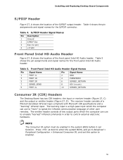
... system BIOS, and go to Advanced > Peripheral Configuration > Enhanced Consumer IR, and set this option to speak the infrared communication language of the front panel Intel HD Audio header. Front Panel Intel HD Audio Header Signal Names Pin Signal Name 1 PORT 1L 3 PORT 1R 5 PORT 2R 7 SENSE_SEND 9 PORT 2L Pin Signal Name 2 GND 4 PRESENCE# 6 SENSE1_RETURN 8 KEY (no pin) 4 +5 VDC Front Panel Intel HD Audio Header Figure 27, B shows the location of other user remotes. Table 5. Installing and Replacing Desktop Board...
... system BIOS, and go to Advanced > Peripheral Configuration > Enhanced Consumer IR, and set this option to speak the infrared communication language of the front panel Intel HD Audio header. Front Panel Intel HD Audio Header Signal Names Pin Signal Name 1 PORT 1L 3 PORT 1R 5 PORT 2R 7 SENSE_SEND 9 PORT 2L Pin Signal Name 2 GND 4 PRESENCE# 6 SENSE1_RETURN 8 KEY (no pin) 4 +5 VDC Front Panel Intel HD Audio Header Figure 27, B shows the location of other user remotes. Table 5. Installing and Replacing Desktop Board...
Product Guide
Page 60
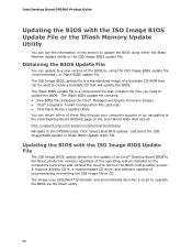
.... Clearing Passwords This procedure assumes that the board is installed in the computer, turn on the computer, and allow it to normal mode. 1. Find the configuration jumper block (see Figure 32). 5. Disconnect the computer's power cord from the AC power source (wall outlet or power adapter). 3. Setup displays the Maintenance menu. 60 Use this menu to the computer. Intel Desktop Board DP55KG Product Guide Table 13. Configure (2-3) After the Power-On Self-Test (POST...
.... Clearing Passwords This procedure assumes that the board is installed in the computer, turn on the computer, and allow it to normal mode. 1. Find the configuration jumper block (see Figure 32). 5. Disconnect the computer's power cord from the AC power source (wall outlet or power adapter). 3. Setup displays the Maintenance menu. 60 Use this menu to the computer. Intel Desktop Board DP55KG Product Guide Table 13. Configure (2-3) After the Power-On Self-Test (POST...
Product Guide
Page 68
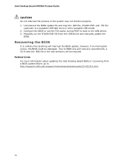
... to the Intel Desktop Board DP55KG page on the computer's hard drive and without the need to update the BIOS. The Iflash BIOS update file contains: • New BIOS file (including the Intel® Management Engine Firmware Image) • Intel® Integrator Toolkit Configuration File (optional) • Intel Flash Memory Update Utility You can use the information in this section to upgrade the BIOS via the Iflash utility. 68 Updating the BIOS with the ISO Image BIOS Update File or the Iflash Memory Update Utility You...
... to the Intel Desktop Board DP55KG page on the computer's hard drive and without the need to update the BIOS. The Iflash BIOS update file contains: • New BIOS file (including the Intel® Management Engine Firmware Image) • Intel® Integrator Toolkit Configuration File (optional) • Intel Flash Memory Update Utility You can use the information in this section to upgrade the BIOS via the Iflash utility. 68 Updating the BIOS with the ISO Image BIOS Update File or the Iflash Memory Update Utility You...
Product Guide
Page 70
... .BIO file, IFLASH.EXE, and .ITK file (optional) to the USB device. 3. however, if an interruption occurs, the BIOS could be required. Configure the BIOS or use the F10 option during POST to boot to a bootable USB flash drive or other bootable USB media. 2. Related Links: For more information about updating the Intel Desktop Board BIOS or recovering from the USB device and manually update the BIOS. Due to http://support.intel.com/support/motherboards/desktop/sb/CS-022312.htm 70 Intel Desktop Board DP55KG Product Guide...
... .BIO file, IFLASH.EXE, and .ITK file (optional) to the USB device. 3. however, if an interruption occurs, the BIOS could be required. Configure the BIOS or use the F10 option during POST to boot to a bootable USB flash drive or other bootable USB media. 2. Related Links: For more information about updating the Intel Desktop Board BIOS or recovering from the USB device and manually update the BIOS. Due to http://support.intel.com/support/motherboards/desktop/sb/CS-022312.htm 70 Intel Desktop Board DP55KG Product Guide...

Product Guide
Page 72
... Windows XP Installation) 1. Setting Up a "RAID Ready" System The Intel Matrix Storage Technology Console software offers the flexibility to upgrade from a single Serial ATA drive to RAID without reinstalling the operating system, when a second SATA hard drive is added to a RAID setup. 72 Intel Desktop Board DP55KG Product Guide Loading the Intel Matrix Storage Technology RAID Drivers and Software (Required for information on supported USB floppy disk drives. Once additional SATA drives have been added to the system, open the Intel Matrix Storage Technology Console Software...
... Windows XP Installation) 1. Setting Up a "RAID Ready" System The Intel Matrix Storage Technology Console software offers the flexibility to upgrade from a single Serial ATA drive to RAID without reinstalling the operating system, when a second SATA hard drive is added to a RAID setup. 72 Intel Desktop Board DP55KG Product Guide Loading the Intel Matrix Storage Technology RAID Drivers and Software (Required for information on supported USB floppy disk drives. Once additional SATA drives have been added to the system, open the Intel Matrix Storage Technology Console Software...
Product Guide
Page 73
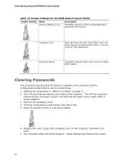
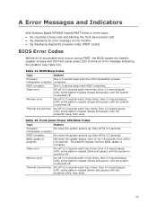
... the BIOS update is powered off for 0.5 seconds. A Error Messages and Indicators Intel Desktop Board DP55KG reports POST errors in progress Off when the update begins, then on the monitor • By displaying diagnostic progress codes (POST codes) BIOS Error Codes Whenever a recoverable error occurs during POST, the BIOS causes the board's speaker to beep and the front panel power LED to blink an error message indicating the problem (see Table 14). Front-panel Power LED Blink Codes Type Pattern Processor On when the system powers up...
... the BIOS update is powered off for 0.5 seconds. A Error Messages and Indicators Intel Desktop Board DP55KG reports POST errors in progress Off when the update begins, then on the monitor • By displaying diagnostic progress codes (POST codes) BIOS Error Codes Whenever a recoverable error occurs during POST, the BIOS causes the board's speaker to beep and the front panel power LED to blink an error message indicating the problem (see Table 14). Front-panel Power LED Blink Codes Type Pattern Processor On when the system powers up...


