Product Guide
Page 2
...any time, without notice. If this product, contact: Intel Corporation, 5200 N.E. Intel Desktop Board DP55KG may contain design defects or errors known as the property of others. Intel and Pentium are referenced in a residential installation. Le présent appareil numerique német pas...Revision -001 -002 -003 Revision History First release of the Intel® Desktop Board DP55KG Product Guide Second release of the Intel® Desktop Board DP55KG Product Guide Third release of the Intel® Desktop Board DP55KG Product Guide Date July 2009 December 2009 April 2010 If an FCC...
...any time, without notice. If this product, contact: Intel Corporation, 5200 N.E. Intel Desktop Board DP55KG may contain design defects or errors known as the property of others. Intel and Pentium are referenced in a residential installation. Le présent appareil numerique német pas...Revision -001 -002 -003 Revision History First release of the Intel® Desktop Board DP55KG Product Guide Second release of the Intel® Desktop Board DP55KG Product Guide Third release of the Intel® Desktop Board DP55KG Product Guide Date July 2009 December 2009 April 2010 If an FCC...
Product Guide
Page 3
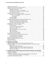
... for Intel® Desktop Board DP55KG. may not be supported without further evaluation by Intel. Document Organization The chapters in this product for installation in personal computers (PC) for other PC or embedded non-PC applications or other hardware components 3 Updating the BIOS: instructions on how to important information. iii Use Only for Intended Applications All Intel Desktop Boards...
... for Intel® Desktop Board DP55KG. may not be supported without further evaluation by Intel. Document Organization The chapters in this product for installation in personal computers (PC) for other PC or embedded non-PC applications or other hardware components 3 Updating the BIOS: instructions on how to important information. iii Use Only for Intended Applications All Intel Desktop Boards...
Product Guide
Page 5
... 20 PCI* and PCI Express* Auto Configuration 20 Security Passwords 20 Hardware Management 21 Hardware Monitoring and Fan Speed Control 21 Intel® Precision Cooling Technology 21 Chassis Intrusion 21 Power Management 22 Software Support 22 ACPI 22 Hardware Support 22 Power Connectors 22...Processor and Voltage Regulator LEDs 27 Back to BIOS Button 28 Speaker...29 Battery ...29 Real-Time Clock 29 2 Installing and Replacing Desktop Board Components Before You Begin 31 Installation Precautions 32 Prevent Power Supply Overload 32 Observe Safety and Regulatory Requirements 32 v
... 20 PCI* and PCI Express* Auto Configuration 20 Security Passwords 20 Hardware Management 21 Hardware Monitoring and Fan Speed Control 21 Intel® Precision Cooling Technology 21 Chassis Intrusion 21 Power Management 22 Software Support 22 ACPI 22 Hardware Support 22 Power Connectors 22...Processor and Voltage Regulator LEDs 27 Back to BIOS Button 28 Speaker...29 Battery ...29 Real-Time Clock 29 2 Installing and Replacing Desktop Board Components Before You Begin 31 Installation Precautions 32 Prevent Power Supply Overload 32 Observe Safety and Regulatory Requirements 32 v
Product Guide
Page 6
Intel Desktop Board DP55KG Product Guide Installing the I/O Shield 33 Installing and Removing the Desktop Board 34 Installing and Removing a Processor 35 Installing a Processor 35 Installing the Processor Fan Heat Sink 40 Connecting the Processor Fan Heat Sink Cable 40 Removing the Processor 40 Installing and Removing System Memory 41 Guidelines for Dual Channel Memory Configuration 41 Two or Four DIMMs 41 Three...
Intel Desktop Board DP55KG Product Guide Installing the I/O Shield 33 Installing and Removing the Desktop Board 34 Installing and Removing a Processor 35 Installing a Processor 35 Installing the Processor Fan Heat Sink 40 Connecting the Processor Fan Heat Sink Cable 40 Removing the Processor 40 Installing and Removing System Memory 41 Guidelines for Dual Channel Memory Configuration 41 Two or Four DIMMs 41 Three...
Product Guide
Page 7
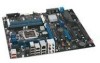
...86 EMC Regulations 88 Ensure Electromagnetic Compatibility (EMC) Compliance 89 Product Certifications 90 Board-Level Certification Markings 90 Chassis and Component Certifications 91 Figures 1. Intel Desktop Board DP55KG Mounting Screw Hole Locations 34 10. Remove the Socket Cover 37 13. Use...28 8. Example Dual Channel Memory Configuration with Four DIMMs 42 20. Installing a DIMM 44 23. Remove the Processor from the Protective Cover 38 14. Intel Desktop Board DP55KG Components 12 2. Install the Processor 38 15. Example Dual Channel Memory Configuration with Three DIMMs...
...86 EMC Regulations 88 Ensure Electromagnetic Compatibility (EMC) Compliance 89 Product Certifications 90 Board-Level Certification Markings 90 Chassis and Component Certifications 91 Figures 1. Intel Desktop Board DP55KG Mounting Screw Hole Locations 34 10. Remove the Socket Cover 37 13. Use...28 8. Example Dual Channel Memory Configuration with Four DIMMs 42 20. Installing a DIMM 44 23. Remove the Processor from the Protective Cover 38 14. Intel Desktop Board DP55KG Components 12 2. Install the Processor 38 15. Example Dual Channel Memory Configuration with Three DIMMs...
Product Guide
Page 19
...pin count (LPC) interface • Intelligent power management, including a programmable wake up event interface • PCI power management support Expandability Intel Desktop Board DP55KG provides the following RAID levels: • RAID 0 • RAID 1 NOTE The Marvell 88SE6145 controller supports single drive non-RAID ...Two PCI Express 2.0 x1 ports • Two PCI bus connectors 19 Desktop Board Features NOTE In order to install separate RAID drivers using the F6 key. Also, during Microsoft Windows XP installation, you must press the F6 key to connect an eSATA drive. The...
...pin count (LPC) interface • Intelligent power management, including a programmable wake up event interface • PCI power management support Expandability Intel Desktop Board DP55KG provides the following RAID levels: • RAID 0 • RAID 1 NOTE The Marvell 88SE6145 controller supports single drive non-RAID ...Two PCI Express 2.0 x1 ports • Two PCI bus connectors 19 Desktop Board Features NOTE In order to install separate RAID drivers using the F6 key. Also, during Microsoft Windows XP installation, you must press the F6 key to connect an eSATA drive. The...
Product Guide
Page 20
... Express* Auto Configuration If you can enter either the supervisor password or the user password to run the BIOS Setup program after installing a Serial ATA. Security Passwords The BIOS includes security features that add-in card. The password prompt is displayed before the computer...) in your computer. Serial ATA Auto Configuration If you install a PCI/PCI Express add-in card. If only the supervisor password is stored in Chapter 3 starting on resetting the password, go to boot the computer. Intel Desktop Board DP55KG Product Guide BIOS The BIOS provides the Power-On Self...
... Express* Auto Configuration If you can enter either the supervisor password or the user password to run the BIOS Setup program after installing a Serial ATA. Security Passwords The BIOS includes security features that add-in card. The password prompt is displayed before the computer...) in your computer. Serial ATA Auto Configuration If you install a PCI/PCI Express add-in card. If only the supervisor password is stored in Chapter 3 starting on resetting the password, go to boot the computer. Intel Desktop Board DP55KG Product Guide BIOS The BIOS provides the Power-On Self...
Product Guide
Page 24
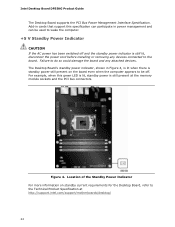
...installing or removing any attached devices. Location of the Standby Power Indicator For more information on the board even when the computer appears to be used to the Technical Product Specification at the memory module sockets and the PCI bus connectors. Intel Desktop Board DP55KG Product Guide The Desktop Board... supports the PCI Bus Power Management Interface Specification. Add-in power management and can be off and the standby power indicator is still present at http://support.intel.com/support/motherboards/desktop/ 24...
...installing or removing any attached devices. Location of the Standby Power Indicator For more information on the board even when the computer appears to be used to the Technical Product Specification at the memory module sockets and the PCI bus connectors. Intel Desktop Board DP55KG Product Guide The Desktop Board... supports the PCI Bus Power Management Interface Specification. Add-in power management and can be off and the standby power indicator is still present at http://support.intel.com/support/motherboards/desktop/ 24...
Product Guide
Page 31
... This chapter tells you how to: • Install the I/O shield • Install and remove the Desktop Board • Install and remove a processor • Install and remove memory • Install and remove a PCI Express x16 graphics card • Connect the Serial ATA cables • Connect...damage components. Follow these guidelines before you can continue to record information about your computer, such as model, serial numbers, installed options, and configuration information. • Electrostatic discharge (ESD) can result in this chapter. Perform the procedures described in ...
... This chapter tells you how to: • Install the I/O shield • Install and remove the Desktop Board • Install and remove a processor • Install and remove memory • Install and remove a PCI Express x16 graphics card • Connect the Serial ATA cables • Connect...damage components. Follow these guidelines before you can continue to record information about your computer, such as model, serial numbers, installed options, and configuration information. • Electrostatic discharge (ESD) can result in this chapter. Perform the procedures described in ...
Product Guide
Page 32
... you can ensure that your safety risk and the possibility of the power supplies output circuits. Intel Desktop Board DP55KG Product Guide Installation Precautions When you install and test the Intel Desktop Board, observe all warnings and cautions in this section and the instructions supplied with these instructions and ...output current rating of each of noncompliance with regional laws and regulations. For information about the Desktop Board's regulatory compliance, refer to qualified technical personnel. If you do not follow the instructions in the installation instructions.
... you can ensure that your safety risk and the possibility of the power supplies output circuits. Intel Desktop Board DP55KG Product Guide Installation Precautions When you install and test the Intel Desktop Board, observe all warnings and cautions in this section and the instructions supplied with these instructions and ...output current rating of each of noncompliance with regional laws and regulations. For information about the Desktop Board's regulatory compliance, refer to qualified technical personnel. If you do not follow the instructions in the installation instructions.

Product Guide
Page 33
Install the I /O Shield 33 Installing the I /O shield before installing the Desktop Board in the chassis. Installing and Replacing Desktop Board Components Installing the I/O Shield The Desktop Board comes with an I/O shield. Place the shield inside the chassis as shown in the chassis, the shield blocks radio frequency transmissions, protects internal components from ... from dust and foreign objects, and promotes correct airflow within the chassis. Press the shield into place so that it fits tightly and securely. When installed in Figure 8.
Install the I /O Shield 33 Installing the I /O shield before installing the Desktop Board in the chassis. Installing and Replacing Desktop Board Components Installing the I/O Shield The Desktop Board comes with an I/O shield. Place the shield inside the chassis as shown in the chassis, the shield blocks radio frequency transmissions, protects internal components from ... from dust and foreign objects, and promotes correct airflow within the chassis. Press the shield into place so that it fits tightly and securely. When installed in Figure 8.

Product Guide
Page 34
... the Desktop Board. Intel Desktop Board DP55KG Mounting Screw Hole Locations 34 Disconnect the computer from its power source before you open the computer can result in personal injury or equipment damage. Figure 9. Failure to your chassis manual for Intel Desktop Board DP55KG. Refer to disconnect the power before performing the procedures described here. Intel Desktop Board DP55KG Product Guide Installing and Removing the Desktop Board CAUTION...
... the Desktop Board. Intel Desktop Board DP55KG Mounting Screw Hole Locations 34 Disconnect the computer from its power source before you open the computer can result in personal injury or equipment damage. Figure 9. Failure to your chassis manual for Intel Desktop Board DP55KG. Refer to disconnect the power before performing the procedures described here. Intel Desktop Board DP55KG Product Guide Installing and Removing the Desktop Board CAUTION...

Product Guide
Page 35
... instructions: 1. Unlatch the socket lever by unplugging the power cord from the socket (Figure 10, A and B). Figure 10. Unlatch the Socket Lever 35 Failure to install the processor on the Desktop Board are given below. Installing and Replacing Desktop Board Components Installing and Removing a Processor Instructions on how to do so could damage the processor and the...
... instructions: 1. Unlatch the socket lever by unplugging the power cord from the socket (Figure 10, A and B). Figure 10. Unlatch the Socket Lever 35 Failure to install the processor on the Desktop Board are given below. Installing and Replacing Desktop Board Components Installing and Removing a Processor Instructions on how to do so could damage the processor and the...

Product Guide
Page 37
... 12, B). Remove the Socket Cover 37 Do not touch the socket contacts. save it for possible future use. NOTE Do not discard the socket cover; Installing and Replacing Desktop Board Components 4. Lift the front edge of the cover and resting your index finger on the rear grip (Figure 12, A). Figure 12.
... 12, B). Remove the Socket Cover 37 Do not touch the socket contacts. save it for possible future use. NOTE Do not discard the socket cover; Installing and Replacing Desktop Board Components 4. Lift the front edge of the cover and resting your index finger on the rear grip (Figure 12, A). Figure 12.

Product Guide
Page 38
... 6. Lower the processor straight down without tilting or sliding it in Figure 14 to touch the bottom of the processor (see Figure 13). Install the Processor 38 Intel Desktop Board DP55KG Product Guide 5. Hold the processor with the posts on the processor align with your fingers with the socket finger cutouts. Hold the processor only...
... 6. Lower the processor straight down without tilting or sliding it in Figure 14 to touch the bottom of the processor (see Figure 13). Install the Processor 38 Intel Desktop Board DP55KG Product Guide 5. Hold the processor with the posts on the processor align with your fingers with the socket finger cutouts. Hold the processor only...
Product Guide
Page 39
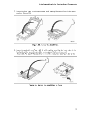
Lower the socket lever (Figure 16, B) while making sure that the front edge of the load plate slides under the load plate tab (Figure 16, C, D). Secure the Load Plate in the open position (Figure 15). Installing and Replacing Desktop Board Components 7. Lower the Load Plate 8. Figure 15. Figure 16. Lower the load plate over the processor while leaving the socket lever in Place 39 Latch the socket lever under the shoulder screw cap as the lever is lowered (Figure 16, A).
Lower the socket lever (Figure 16, B) while making sure that the front edge of the load plate slides under the load plate tab (Figure 16, C, D). Secure the Load Plate in the open position (Figure 15). Installing and Replacing Desktop Board Components 7. Lower the Load Plate 8. Figure 15. Figure 16. Lower the load plate over the processor while leaving the socket lever in Place 39 Latch the socket lever under the shoulder screw cap as the lever is lowered (Figure 16, A).

Product Guide
Page 40
...Intel Desktop Board DP55KG Product Guide Installing the Processor Fan Heat Sink Intel Desktop Board DP55KG has mounting holes for a processor fan heat sink. Connecting the Processor Fan Heat Sink Power Cable to the Processor Fan Header Removing the Processor For instructions on how to attach the processor fan heat sink to the Desktop Board..., refer to the boxed processor manual or boxed thermal solution manual. Connecting the Processor Fan Heat Sink Cable Connect the processor fan heat sink power cable to the processor installation manual. 40 A fan with...
...Intel Desktop Board DP55KG Product Guide Installing the Processor Fan Heat Sink Intel Desktop Board DP55KG has mounting holes for a processor fan heat sink. Connecting the Processor Fan Heat Sink Power Cable to the Processor Fan Header Removing the Processor For instructions on how to attach the processor fan heat sink to the Desktop Board..., refer to the boxed processor manual or boxed thermal solution manual. Connecting the Processor Fan Heat Sink Cable Connect the processor fan heat sink power cable to the processor installation manual. 40 A fan with...
Product Guide
Page 41
... for Dual Channel Memory Configuration Before installing DIMMs, read and follow these guidelines for dual channel memory configuration. Installing and Replacing Desktop Board Components Installing and Removing System Memory Desktop board DP55KG has four 240-pin DDR3 DIMM sockets arranged as DIMM 0 and DIMM 1 in DIMM 0 (blue) of channels A and B. NOTE The Intel P55 Express Chipset requires memory to...
... for Dual Channel Memory Configuration Before installing DIMMs, read and follow these guidelines for dual channel memory configuration. Installing and Replacing Desktop Board Components Installing and Removing System Memory Desktop board DP55KG has four 240-pin DDR3 DIMM sockets arranged as DIMM 0 and DIMM 1 in DIMM 0 (blue) of channels A and B. NOTE The Intel P55 Express Chipset requires memory to...
Product Guide
Page 42
Intel Desktop Board DP55KG Product Guide If additional memory is to use three DIMMs in a dual-channel configuration, install a matched pair of DIMMs equal in speed and size in DIMM 0 (blue) and DIMM 1 (black) of channel B (see Figure 19). Figure 20. Example Dual Channel ... configurations will result in single channel memory operation. 42 Example Dual Channel Memory Configuration with Four DIMMs Three DIMMs If you want to be used, install another matched pair of DIMMs in DIMM 1 (black) in either DIMM 0 or DIMM 1 of channel...
Intel Desktop Board DP55KG Product Guide If additional memory is to use three DIMMs in a dual-channel configuration, install a matched pair of DIMMs equal in speed and size in DIMM 0 (blue) and DIMM 1 (black) of channel B (see Figure 19). Figure 20. Example Dual Channel ... configurations will result in single channel memory operation. 42 Example Dual Channel Memory Configuration with Four DIMMs Three DIMMs If you want to be used, install another matched pair of DIMMs in DIMM 1 (black) in either DIMM 0 or DIMM 1 of channel...

Product Guide
Page 43
All the notches should match with the DDR3 DIMM. Use DDR3 DIMMs 43 Figure 21. Installing and Replacing Desktop Board Components Installing DIMMs To make sure you have the correct DIMM, place it on the illustration of the DDR3 DIMM in Figure 21.
All the notches should match with the DDR3 DIMM. Use DDR3 DIMMs 43 Figure 21. Installing and Replacing Desktop Board Components Installing DIMMs To make sure you have the correct DIMM, place it on the illustration of the DDR3 DIMM in Figure 21.


