Product Guide
Page 5
Contents 1 Desktop Board Features Supported Operating Systems 11 Desktop Board Components 12 Processor ...14 Main Memory...15 Intel® P55 Express Chipset 16 Audio Subsystem 16 LAN Subsystem 16 Bluetooth* Technology Support 17 USB 2.0 Support 17 Serial ATA Support 18 Legacy I/O ...19... 26 Processor and Voltage Regulator LEDs 27 Back to BIOS Button 28 Speaker...29 Battery ...29 Real-Time Clock 29 2 Installing and Replacing Desktop Board Components Before You Begin 31 Installation Precautions 32 Prevent Power Supply Overload 32 Observe Safety and Regulatory Requirements 32 v
Contents 1 Desktop Board Features Supported Operating Systems 11 Desktop Board Components 12 Processor ...14 Main Memory...15 Intel® P55 Express Chipset 16 Audio Subsystem 16 LAN Subsystem 16 Bluetooth* Technology Support 17 USB 2.0 Support 17 Serial ATA Support 18 Legacy I/O ...19... 26 Processor and Voltage Regulator LEDs 27 Back to BIOS Button 28 Speaker...29 Battery ...29 Real-Time Clock 29 2 Installing and Replacing Desktop Board Components Before You Begin 31 Installation Precautions 32 Prevent Power Supply Overload 32 Observe Safety and Regulatory Requirements 32 v
Product Guide
Page 6
Intel Desktop Board DP55KG Product Guide Installing the I/O Shield 33 Installing and Removing the Desktop Board 34 Installing and Removing a Processor 35 Installing a Processor 35 Installing the Processor Fan Heat Sink 40 Connecting the Processor Fan Heat Sink Cable 40 Removing the Processor 40 Installing and Removing System Memory 41 Guidelines for Dual Channel Memory...Image BIOS Update File 68 Updating the BIOS with the Iflash Memory Update Utility 69 Recovering the BIOS 70 4 Configuring for RAID Using Intel® Matrix Storage Technology Configuring the BIOS 71 Creating Your RAID...
Intel Desktop Board DP55KG Product Guide Installing the I/O Shield 33 Installing and Removing the Desktop Board 34 Installing and Removing a Processor 35 Installing a Processor 35 Installing the Processor Fan Heat Sink 40 Connecting the Processor Fan Heat Sink Cable 40 Removing the Processor 40 Installing and Removing System Memory 41 Guidelines for Dual Channel Memory...Image BIOS Update File 68 Updating the BIOS with the Iflash Memory Update Utility 69 Recovering the BIOS 70 4 Configuring for RAID Using Intel® Matrix Storage Technology Configuring the BIOS 71 Creating Your RAID...
Product Guide
Page 7
...the Load Plate 36 12. Remove the Processor from the Protective Cover 38 14. Example Dual Channel Memory Configuration with Three DIMMs 42 21. Connecting the Serial ATA Cables 49 27. Intel Desktop Board DP55KG Components 12 2. Location of the Standby Power Indicator 24 5. Use DDR3 DIMMs 43 22. SATA ...European Union Declaration of Conformity Statement 80 Product Ecology Statements 81 Recycling Considerations 81 Lead-free 2LI/Pb-free 2LI Board 84 Restriction of the Processor and Voltage Regulator LEDs 27 7. Intel Desktop Board DP55KG Mounting Screw Hole Locations 34 10.
...the Load Plate 36 12. Remove the Processor from the Protective Cover 38 14. Example Dual Channel Memory Configuration with Three DIMMs 42 21. Connecting the Serial ATA Cables 49 27. Intel Desktop Board DP55KG Components 12 2. Location of the Standby Power Indicator 24 5. Use DDR3 DIMMs 43 22. SATA ...European Union Declaration of Conformity Statement 80 Product Ecology Statements 81 Recycling Considerations 81 Lead-free 2LI/Pb-free 2LI Board 84 Restriction of the Processor and Voltage Regulator LEDs 27 7. Intel Desktop Board DP55KG Mounting Screw Hole Locations 34 10.
Product Guide
Page 9
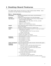
... MHz, and DDR3 1066 MHz DIMMs • Support for non-ECC memory • Support for up to 16 GB of system memory Chipset Intel® P55 Express Chipset consisting of Intel® Desktop Board DP55KG. Table 1. 1 Desktop Board Features This chapter briefly describes the features of the Intel P55 Platform Controller Hub (PCH) Graphics Audio Expansion Capabilities Support for multiple...
... MHz, and DDR3 1066 MHz DIMMs • Support for non-ECC memory • Support for up to 16 GB of system memory Chipset Intel® P55 Express Chipset consisting of Intel® Desktop Board DP55KG. Table 1. 1 Desktop Board Features This chapter briefly describes the features of the Intel P55 Platform Controller Hub (PCH) Graphics Audio Expansion Capabilities Support for multiple...
Product Guide
Page 10
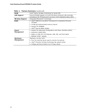
Intel Desktop Board DP55KG Product Guide Table 1. Feature Summary (continued) RAID Intel® Matrix Storage Technology for Serial ATA LAN Support Intel 82578DM Gigabit (10/100/1000 Mb/s) Ethernet LAN controller including an RJ-45 back panel connector with integrated status LEDs Wireless Support BIOS Integrated Bluetooth* technology • Intel...® Platform Innovation Framework for extensible firmware interface • 16 Mb symmetrical flash memory device • Support for SMBIOS • Intel® Express BIOS Update Power ...
Intel Desktop Board DP55KG Product Guide Table 1. Feature Summary (continued) RAID Intel® Matrix Storage Technology for Serial ATA LAN Support Intel 82578DM Gigabit (10/100/1000 Mb/s) Ethernet LAN controller including an RJ-45 back panel connector with integrated status LEDs Wireless Support BIOS Integrated Bluetooth* technology • Intel...® Platform Innovation Framework for extensible firmware interface • 16 Mb symmetrical flash memory device • Support for SMBIOS • Intel® Express BIOS Update Power ...
Product Guide
Page 15
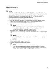
... gold-plated contacts arranged in graphics cards and other system resources. 15 Desktop Board Features Main Memory NOTE To be fully compliant with all applicable Intel ® SDRAM memory specifications, the board should be populated with a voltage rating higher than 4 GB because of the memory used by add-in two channels • 1600+/1333/1066 MHz DDR3...
... gold-plated contacts arranged in graphics cards and other system resources. 15 Desktop Board Features Main Memory NOTE To be fully compliant with all applicable Intel ® SDRAM memory specifications, the board should be populated with a voltage rating higher than 4 GB because of the memory used by add-in two channels • 1600+/1333/1066 MHz DDR3...
Product Guide
Page 23
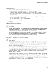
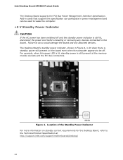
... support multiple wake events from the PCI and/or USB buses exceeds power supply capacity, the Desktop Board may lose register settings stored in memory. While in the S3 sleep state, the computer will appear to its last known awake state. 23 When signaled by the LED turning amber. LAN ... the front panel, the sleep state is indicated by a wake-up of the computer through a network. Failure to provide adequate standby current when using this Desktop Board must be off as follows: • The fans are on when the computer is in the ACPI S0 state. • The fans are off when...
... support multiple wake events from the PCI and/or USB buses exceeds power supply capacity, the Desktop Board may lose register settings stored in memory. While in the S3 sleep state, the computer will appear to its last known awake state. 23 When signaled by the LED turning amber. LAN ... the front panel, the sleep state is indicated by a wake-up of the computer through a network. Failure to provide adequate standby current when using this Desktop Board must be off as follows: • The fans are on when the computer is in the ACPI S0 state. • The fans are off when...
Product Guide
Page 24
... power is still present at http://support.intel.com/support/motherboards/desktop/ 24 Location of the Standby Power Indicator For more information on the board even when the computer appears to the Technical Product Specification at the memory module sockets and the PCI bus connectors. Intel Desktop Board DP55KG Product Guide The Desktop Board supports the PCI Bus Power Management Interface...
... power is still present at http://support.intel.com/support/motherboards/desktop/ 24 Location of the Standby Power Indicator For more information on the board even when the computer appears to the Technical Product Specification at the memory module sockets and the PCI bus connectors. Intel Desktop Board DP55KG Product Guide The Desktop Board supports the PCI Bus Power Management Interface...
Product Guide
Page 31
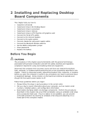
... steps in each procedure in this chapter only at an ESD workstation using and modifying electronic equipment. Some circuitry on the board can provide some ESD protection by wearing an antistatic wrist strap and attaching it to a metal part of the procedures described...any of the computer chassis. 31 2 Installing and Replacing Desktop Board Components This chapter tells you how to: • Install the I/O shield • Install and remove the Desktop Board • Install and remove a processor • Install and remove memory • Install and remove a PCI Express x16 graphics ...
... steps in each procedure in this chapter only at an ESD workstation using and modifying electronic equipment. Some circuitry on the board can provide some ESD protection by wearing an antistatic wrist strap and attaching it to a metal part of the procedures described...any of the computer chassis. 31 2 Installing and Replacing Desktop Board Components This chapter tells you how to: • Install the I/O shield • Install and remove the Desktop Board • Install and remove a processor • Install and remove memory • Install and remove a PCI Express x16 graphics ...
Product Guide
Page 41
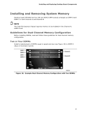
... (see Figure 18) in the Channel A, DIMM 0 slot. NOTE The Intel P55 Express Chipset requires memory to be installed in DIMM 0 (blue) of channels A and B. Example Dual Channel Memory Configuration with Two DIMMs 41 Installing and Replacing Desktop Board Components Installing and Removing System Memory Desktop board DP55KG has four 240-pin DDR3 DIMM sockets arranged as DIMM 0 and...
... (see Figure 18) in the Channel A, DIMM 0 slot. NOTE The Intel P55 Express Chipset requires memory to be installed in DIMM 0 (blue) of channels A and B. Example Dual Channel Memory Configuration with Two DIMMs 41 Installing and Replacing Desktop Board Components Installing and Removing System Memory Desktop board DP55KG has four 240-pin DDR3 DIMM sockets arranged as DIMM 0 and...
Product Guide
Page 42
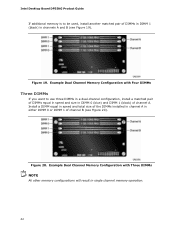
... Four DIMMs Three DIMMs If you want to be used, install another matched pair of DIMMs in DIMM 1 (black) in single channel memory operation. 42 Intel Desktop Board DP55KG Product Guide If additional memory is to use three DIMMs in a dual-channel configuration, install a matched pair of DIMMs equal in speed and size in either DIMM...
... Four DIMMs Three DIMMs If you want to be used, install another matched pair of DIMMs in DIMM 1 (black) in single channel memory operation. 42 Intel Desktop Board DP55KG Product Guide If additional memory is to use three DIMMs in a dual-channel configuration, install a matched pair of DIMMs equal in speed and size in either DIMM...
Product Guide
Page 44
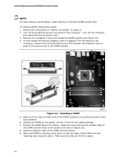
... by the edges, remove it from its anti-static package. 7. Make sure the clips are pushed outward to the open position. 6. Intel Desktop Board DP55KG Product Guide NOTE For best memory performance, install memory in place. 44 Turn off the computer and disconnect the AC power cord. 3. Insert the bottom edge of the DIMM until the...
... by the edges, remove it from its anti-static package. 7. Make sure the clips are pushed outward to the open position. 6. Intel Desktop Board DP55KG Product Guide NOTE For best memory performance, install memory in place. 44 Turn off the computer and disconnect the AC power cord. 3. Insert the bottom edge of the DIMM until the...
Product Guide
Page 61
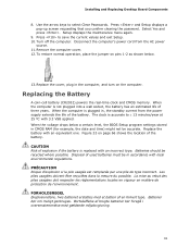
...; 13 minutes/year at 25 ºC with local environmental regulations. Installing and Replacing Desktop Board Components 8. Disposal of the battery. Press to select Clear Passwords. Replacing the Battery A coin-cell battery (CR2032) powers the real-time clock and CMOS memory. Replace the cover, plug in , the standby current from the AC power source...
...; 13 minutes/year at 25 ºC with local environmental regulations. Installing and Replacing Desktop Board Components 8. Disposal of the battery. Press to select Clear Passwords. Replacing the Battery A coin-cell battery (CR2032) powers the real-time clock and CMOS memory. Replace the cover, plug in , the standby current from the AC power source...
Product Guide
Page 67
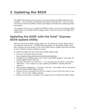
... installation wizards. Your system will be used to update the BIOS by pressing the key after the Power-On Self-Test (POST) memory test begins and before the operating system boot begins. This chapter tells you how to view and change the BIOS settings for multiple ... the BIOS The BIOS Setup program can be rebooted at the last Express BIOS Update window. 5. Navigate to the Intel World Wide Web site: http://support.intel.com/support/motherboards/desktop/ 2. Go to the DP55KG page, click "[view] Latest BIOS updates," and select the Express BIOS Update utility file. 3. Download the file...
... installation wizards. Your system will be used to update the BIOS by pressing the key after the Power-On Self-Test (POST) memory test begins and before the operating system boot begins. This chapter tells you how to view and change the BIOS settings for multiple ... the BIOS The BIOS Setup program can be rebooted at the last Express BIOS Update window. 5. Navigate to the Intel World Wide Web site: http://support.intel.com/support/motherboards/desktop/ 2. Go to the DP55KG page, click "[view] Latest BIOS updates," and select the Express BIOS Update utility file. 3. Download the file...
Product Guide
Page 68
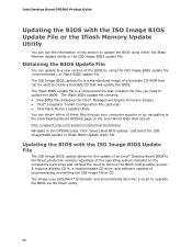
...this section to update the BIOS. Updating the BIOS with the ISO Image BIOS Update File or the Iflash Memory Update Utility You can be used to remove the BIOS configuration jumper. The image uses ISOLINUX* bootloader and automatically launches a ...Intel Desktop Board DP55KG Product Guide Updating the BIOS with the ISO Image BIOS Update File The ISO Image BIOS update allows for the update of an Intel® Desktop Board BIOS to the latest production release regardless of the operating system installed on the Intel World Wide Web site at: http://support.intel.com/support/motherboards/desktop...
...this section to update the BIOS. Updating the BIOS with the ISO Image BIOS Update File or the Iflash Memory Update Utility You can be used to remove the BIOS configuration jumper. The image uses ISOLINUX* bootloader and automatically launches a ...Intel Desktop Board DP55KG Product Guide Updating the BIOS with the ISO Image BIOS Update File The ISO Image BIOS update allows for the update of an Intel® Desktop Board BIOS to the latest production release regardless of the operating system installed on the Intel World Wide Web site at: http://support.intel.com/support/motherboards/desktop...
Product Guide
Page 69
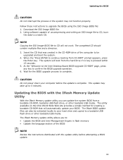
... of uncompressing and writing an ISO image file to CD, burn the data to complete. The update may not function properly. The Iflash Memory update utility allows you can also be upgraded and boot the system. 4. Using software capable of the BIOS NOTE Review the instructions distributed ... BIOS file: 1. Updating the BIOS with the update utility before the update is pressed within 15 seconds. 5. At the "Welcome to the Intel Desktop Board BIOS Upgrade CD-ROM" page, press any key to a bootable USB flash drive or other bootable USB media. The utility available on the...
... of uncompressing and writing an ISO image file to CD, burn the data to complete. The update may not function properly. The Iflash Memory update utility allows you can also be upgraded and boot the system. 4. Using software capable of the BIOS NOTE Review the instructions distributed ... BIOS file: 1. Updating the BIOS with the update utility before the update is pressed within 15 seconds. 5. At the "Welcome to the Intel Desktop Board BIOS Upgrade CD-ROM" page, press any key to a bootable USB flash drive or other bootable USB media. The utility available on the...
Product Guide
Page 71
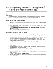
...RAID 0 or RAID 1 (if only two SATA drives are available), RAID 5 and RAID 10 (these options will see the following Intel Matrix Storage Manager option ROM status message on the remaining portion of your settings by pressing . Configuring the BIOS 1. Creating Your RAID .... 5. Exit the Option ROM user interface by pressing after the Power-On-Self-Test (POST) memory tests begin. 3. 4 Configuring for RAID Using Intel® Matrix Storage Technology NOTE Intel Matrix Storage Technology requires Microsoft Windows 7, Microsoft Windows Vista, or Microsoft Windows XP operating system and ...
...RAID 0 or RAID 1 (if only two SATA drives are available), RAID 5 and RAID 10 (these options will see the following Intel Matrix Storage Manager option ROM status message on the remaining portion of your settings by pressing . Configuring the BIOS 1. Creating Your RAID .... 5. Exit the Option ROM user interface by pressing after the Power-On-Self-Test (POST) memory tests begin. 3. 4 Configuring for RAID Using Intel® Matrix Storage Technology NOTE Intel Matrix Storage Technology requires Microsoft Windows 7, Microsoft Windows Vista, or Microsoft Windows XP operating system and ...
Product Guide
Page 73
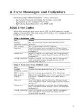
...pause (off), entire pattern repeats (beeps and pause) until the system is powered off for 0.5 seconds. A Error Messages and Indicators Intel Desktop Board DP55KG reports POST errors in progress Off when the update begins, then on the monitor • By displaying diagnostic progress codes (POST codes) ...for 0.5 seconds. initialization complete POST complete On when the system powers up , then off . POST complete One 0.5 second beep when POST completes. Memory error On-off (0.5 seconds each ) four times, then 3.0 second pause (off . BIOS update in three ways: • By sounding a ...
...pause (off), entire pattern repeats (beeps and pause) until the system is powered off for 0.5 seconds. A Error Messages and Indicators Intel Desktop Board DP55KG reports POST errors in progress Off when the update begins, then on the monitor • By displaying diagnostic progress codes (POST codes) ...for 0.5 seconds. initialization complete POST complete On when the system powers up , then off . POST complete One 0.5 second beep when POST completes. Memory error On-off (0.5 seconds each ) four times, then 3.0 second pause (off . BIOS update in three ways: • By sounding a ...

Product Guide
Page 74
...). The firmware has detected that a CMOS Checksum Error occurred. The installed amount of memory in Channel B. The system chassis was previously shutdown due to the amount of memory in each channel. 74 The firmware has detected that a CMOS battery failure occurred. ...The firmware has detected that the system memory has decreased. SERIAL PRESENCE DETECT (SPD) device data missing or inconclusive. Table 16. Table 16 gives an explanation of memory installed in Channel A is required for reliable operation. Intel Desktop Board DP55KG Product Guide BIOS Error Messages When ...
...). The firmware has detected that a CMOS Checksum Error occurred. The installed amount of memory in Channel B. The system chassis was previously shutdown due to the amount of memory in each channel. 74 The firmware has detected that a CMOS battery failure occurred. ...The firmware has detected that the system memory has decreased. SERIAL PRESENCE DETECT (SPD) device data missing or inconclusive. Table 16. Table 16 gives an explanation of memory installed in Channel A is required for reliable operation. Intel Desktop Board DP55KG Product Guide BIOS Error Messages When ...
Product Guide
Page 76
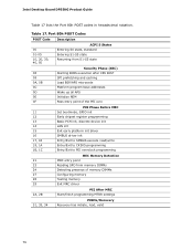
... 21 MRC entry point 23 Reading SPD from memory DIMMs 24 Detecting presence of memory DIMMs 27 Configuring memory 28 Testing memory 29 Exit MRC driver 2A, 2B PEI After MRC Start/finish programming MTRR settings 31, 33, 34 PEIMs/Recovery Recovery has initiate, load, valid 76 Intel Desktop Board DP55KG Product Guide Table 17 lists the Port...
... 21 MRC entry point 23 Reading SPD from memory DIMMs 24 Detecting presence of memory DIMMs 27 Configuring memory 28 Testing memory 29 Exit MRC driver 2A, 2B PEI After MRC Start/finish programming MTRR settings 31, 33, 34 PEIMs/Recovery Recovery has initiate, load, valid 76 Intel Desktop Board DP55KG Product Guide Table 17 lists the Port...


