Product Guide
Page 3
...of product features 2 Installing and Replacing Desktop Board Components: instructions on how to update the BIOS 4 Configuring for RAID Using Intel® Matrix Storage Technology: information ...BIOS error messages and beep codes B Regulatory Compliance: describes the board's adherence to safety standards and EMC regulations and its product certifications Conventions The following conventions are evaluated as medical, industrial, alarm systems, test equipment, etc. Use Only for Intended Applications All Intel Desktop Boards are used in this product for Intel® Desktop Board DP55KG...
...of product features 2 Installing and Replacing Desktop Board Components: instructions on how to update the BIOS 4 Configuring for RAID Using Intel® Matrix Storage Technology: information ...BIOS error messages and beep codes B Regulatory Compliance: describes the board's adherence to safety standards and EMC regulations and its product certifications Conventions The following conventions are evaluated as medical, industrial, alarm systems, test equipment, etc. Use Only for Intended Applications All Intel Desktop Boards are used in this product for Intel® Desktop Board DP55KG...
Product Guide
Page 5
... 1 Desktop Board Features Supported Operating Systems 11 Desktop Board Components 12 Processor ...14 Main Memory...15 Intel® P55 Express Chipset 16 Audio Subsystem 16 LAN Subsystem 16 Bluetooth* Technology Support 17 USB 2.0 Support 17 Serial ATA Support 18 Legacy I/O ...19 Expandability...19 BIOS ...20... 25 Onboard Power Button 26 Processor and Voltage Regulator LEDs 27 Back to BIOS Button 28 Speaker...29 Battery ...29 Real-Time Clock 29 2 Installing and Replacing Desktop Board Components Before You Begin 31 Installation Precautions 32 Prevent Power Supply Overload 32 ...
... 1 Desktop Board Features Supported Operating Systems 11 Desktop Board Components 12 Processor ...14 Main Memory...15 Intel® P55 Express Chipset 16 Audio Subsystem 16 LAN Subsystem 16 Bluetooth* Technology Support 17 USB 2.0 Support 17 Serial ATA Support 18 Legacy I/O ...19 Expandability...19 BIOS ...20... 25 Onboard Power Button 26 Processor and Voltage Regulator LEDs 27 Back to BIOS Button 28 Speaker...29 Battery ...29 Real-Time Clock 29 2 Installing and Replacing Desktop Board Components Before You Begin 31 Installation Precautions 32 Prevent Power Supply Overload 32 ...
Product Guide
Page 6
Intel Desktop Board DP55KG Product Guide Installing the I/O Shield 33 Installing and Removing the Desktop Board 34 Installing and Removing a Processor 35 Installing a Processor 35 Installing the Processor Fan Heat Sink 40 Connecting the Processor Fan Heat Sink...Supply Cables 57 Connecting the Bluetooth Antenna 58 Setting the BIOS Configuration Jumper 59 Clearing Passwords 60 Replacing the Battery 61 3 Updating the BIOS Updating the BIOS with the Intel® Express BIOS Update Utility 67 Updating the BIOS with the ISO Image BIOS Update File or the Iflash Memory Update Utility 68 ...
Intel Desktop Board DP55KG Product Guide Installing the I/O Shield 33 Installing and Removing the Desktop Board 34 Installing and Removing a Processor 35 Installing a Processor 35 Installing the Processor Fan Heat Sink 40 Connecting the Processor Fan Heat Sink...Supply Cables 57 Connecting the Bluetooth Antenna 58 Setting the BIOS Configuration Jumper 59 Clearing Passwords 60 Replacing the Battery 61 3 Updating the BIOS Updating the BIOS with the Intel® Express BIOS Update Utility 67 Updating the BIOS with the ISO Image BIOS Update File or the Iflash Memory Update Utility 68 ...
Product Guide
Page 7
...Location of the Standby Power Indicator 24 5. Install the Processor 38 15. Example Dual Channel Memory Configuration with Three DIMMs 42 21. Intel Desktop Board DP55KG Mounting Screw Hole Locations 34 10. Installing a PCI Express x16 Graphics Card 46 24. Removing a PCI Express x16 Graphics Card 47 ...25. Remove the Socket Cover 37 13. Contents A Error Messages and Indicators BIOS Error Codes 73 BIOS Error Messages 74 Port 80h POST Codes 75 B Regulatory Compliance Safety Standards 79 Place Battery Marking 79 European Union Declaration ...
...Location of the Standby Power Indicator 24 5. Install the Processor 38 15. Example Dual Channel Memory Configuration with Three DIMMs 42 21. Intel Desktop Board DP55KG Mounting Screw Hole Locations 34 10. Installing a PCI Express x16 Graphics Card 46 24. Removing a PCI Express x16 Graphics Card 47 ...25. Remove the Socket Cover 37 13. Contents A Error Messages and Indicators BIOS Error Codes 73 BIOS Error Messages 74 Port 80h POST Codes 75 B Regulatory Compliance Safety Standards 79 Place Battery Marking 79 European Union Declaration ...
Product Guide
Page 8
... Second Level Interconnect Marks 85 20. EMC Regulations 88 22. Back Panel Audio Connectors 55 29. Intel Desktop Board DP55KG China RoHS Material Self Declaration Table 87 Tables 1. BIOS Error Messages 74 17. Intel Desktop Board DP55KG Components 13 3. Jumper Settings for the BIOS Setup Program Modes 60 14. Front Panel CIR Receiver (Input) Header Signal Names 52 7. Chassis Intrusion...
... Second Level Interconnect Marks 85 20. EMC Regulations 88 22. Back Panel Audio Connectors 55 29. Intel Desktop Board DP55KG China RoHS Material Self Declaration Table 87 Tables 1. BIOS Error Messages 74 17. Intel Desktop Board DP55KG Components 13 3. Jumper Settings for the BIOS Setup Program Modes 60 14. Front Panel CIR Receiver (Input) Header Signal Names 52 7. Chassis Intrusion...
Product Guide
Page 10
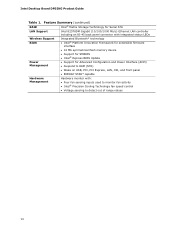
... Platform Innovation Framework for extensible firmware interface • 16 Mb symmetrical flash memory device • Support for SMBIOS • Intel® Express BIOS Update Power Management • Support for Advanced Configuration and Power Interface (ACPI) • Suspend to RAM (STR) •...* capable Hardware Management Hardware monitor with: • Four fan sensing inputs used to monitor fan activity • Intel® Precision Cooling Technology fan speed control • Voltage sensing to detect out of range values 10 Intel Desktop Board DP55KG Product Guide Table 1.
... Platform Innovation Framework for extensible firmware interface • 16 Mb symmetrical flash memory device • Support for SMBIOS • Intel® Express BIOS Update Power Management • Support for Advanced Configuration and Power Interface (ACPI) • Suspend to RAM (STR) •...* capable Hardware Management Hardware monitor with: • Four fan sensing inputs used to monitor fan activity • Intel® Precision Cooling Technology fan speed control • Voltage sensing to detect out of range values 10 Intel Desktop Board DP55KG Product Guide Table 1.
Product Guide
Page 13
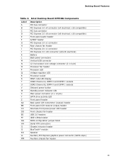
Desktop Board Features Table 2. x16 compatible) PCI bus connector PCI Express 2.0 x8 connector (x8 electrical; x16 compatible) Front panel audio header S/PDIF header PCI Express 2.0 x1 ... panel power LED header Front chassis fan header USB 2.0 headers IEEE 1394a header BIOS configuration jumper block Serial ATA connectors Chassis intrusion header BlueTooth* module Speaker Auxiliary PCI Express graphics power connector (SATA-style) Auxiliary chassis fan header 13 Intel Desktop Board DP55KG Components Label A B C D E F G H I J K L M N O P Q R S T U V W X Y Z AA BB CC DD EE FF GG HH II ...
Desktop Board Features Table 2. x16 compatible) PCI bus connector PCI Express 2.0 x8 connector (x8 electrical; x16 compatible) Front panel audio header S/PDIF header PCI Express 2.0 x1 ... panel power LED header Front chassis fan header USB 2.0 headers IEEE 1394a header BIOS configuration jumper block Serial ATA connectors Chassis intrusion header BlueTooth* module Speaker Auxiliary PCI Express graphics power connector (SATA-style) Auxiliary chassis fan header 13 Intel Desktop Board DP55KG Components Label A B C D E F G H I J K L M N O P Q R S T U V W X Y Z AA BB CC DD EE FF GG HH II ...
Product Guide
Page 14
... Intel Desktop Board DP55KG http://www.intel.com/products/motherboard/DP55KG /index.htm • Supported processors http://processormatch.intel.com • Chipset information http://www.intel.com/products/desktop/chipsets/inde x.htm • BIOS and driver updates http://downloadcenter.intel.com/ • Integration information http://www.intel.com/support/go to the Desktop Board through the LGA1156 socket. Intel Desktop Board DP55KG supports an Intel processor in damage to the board...
... Intel Desktop Board DP55KG http://www.intel.com/products/motherboard/DP55KG /index.htm • Supported processors http://processormatch.intel.com • Chipset information http://www.intel.com/products/desktop/chipsets/inde x.htm • BIOS and driver updates http://downloadcenter.intel.com/ • Integration information http://www.intel.com/support/go to the Desktop Board through the LGA1156 socket. Intel Desktop Board DP55KG supports an Intel processor in damage to the board...
Product Guide
Page 15
.... 15 These operating systems will attempt to configure the memory controller for single- Desktop Board Features Main Memory NOTE To be fully compliant with all applicable Intel ® SDRAM memory specifications, the board should be populated with a voltage rating higher than 4 GB because of the ...support on the screen at power up. or double-sided DIMMs with a voltage rating of BIOS and manual memory tuning. and dual-channel memory interleaving • Unbuffered, non-registered single- The BIOS will report less than 1.65 V may vary. • Support for normal operation.
.... 15 These operating systems will attempt to configure the memory controller for single- Desktop Board Features Main Memory NOTE To be fully compliant with all applicable Intel ® SDRAM memory specifications, the board should be populated with a voltage rating higher than 4 GB because of the ...support on the screen at power up. or double-sided DIMMs with a voltage rating of BIOS and manual memory tuning. and dual-channel memory interleaving • Unbuffered, non-registered single- The BIOS will report less than 1.65 V may vary. • Support for normal operation.
Product Guide
Page 17
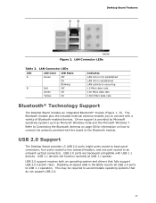
...vertical connector). USB 2.0 Support The Desktop Board provides 13 USB 2.0 ports (eight ports routed to back panel connectors, four ports routed to two onboard headers, and one port routed to the Bluetooth module. Disabling Hi-Speed USB in the BIOS reverts all USB 2.0 ports to ...accommodate operating systems that fully support USB 2.0 transfer rates. LAN Connector LEDs Table 3. USB 1.1 devices will function normally at USB 1.1 speeds. Desktop Board Features Figure 2.
...vertical connector). USB 2.0 Support The Desktop Board provides 13 USB 2.0 ports (eight ports routed to back panel connectors, four ports routed to two onboard headers, and one port routed to the Bluetooth module. Disabling Hi-Speed USB in the BIOS reverts all USB 2.0 ports to ...accommodate operating systems that fully support USB 2.0 transfer rates. LAN Connector LEDs Table 3. USB 1.1 devices will function normally at USB 1.1 speeds. Desktop Board Features Figure 2.
Product Guide
Page 19
...installation, you must press the F6 key to use supported onboard RAID features, you must first enable RAID in the BIOS. Refer to your operating system installation documentation for both AHCI and RAID without the need to connect an eSATA drive.... 19 Both Microsoft Windows Vista and Microsoft Windows 7 include the necessary RAID drivers for more information about installing drivers during installation. Legacy I/O Intel Desktop Board DP55KG includes an I/O controller that provides the following legacy I/O features: • Consumer Infrared (CIR) support • Low pin count (LPC...
...installation, you must press the F6 key to use supported onboard RAID features, you must first enable RAID in the BIOS. Refer to your operating system installation documentation for both AHCI and RAID without the need to connect an eSATA drive.... 19 Both Microsoft Windows Vista and Microsoft Windows 7 include the necessary RAID drivers for more information about installing drivers during installation. Legacy I/O Intel Desktop Board DP55KG includes an I/O controller that provides the following legacy I/O features: • Consumer Infrared (CIR) support • Low pin count (LPC...
Product Guide
Page 20
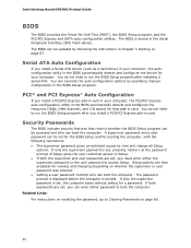
... or user password was entered. • Setting a user password restricts who can be updated by specifying manual configuration in the BIOS automatically detects and configures the device for a password. If only the supervisor password is set, pressing at the password prompt of...Express* Auto Configuration If you install a PCI/PCI Express add-in Chapter 3 starting on page 60. 20 Intel Desktop Board DP55KG Product Guide BIOS The BIOS provides the Power-On Self-Test (POST), the BIOS Setup program, and the PCI/PCI Express and SATA auto-configuration utilities. Security Passwords The...
... or user password was entered. • Setting a user password restricts who can be updated by specifying manual configuration in the BIOS automatically detects and configures the device for a password. If only the supervisor password is set, pressing at the password prompt of...Express* Auto Configuration If you install a PCI/PCI Express add-in Chapter 3 starting on page 60. 20 Intel Desktop Board DP55KG Product Guide BIOS The BIOS provides the Power-On Self-Test (POST), the BIOS Setup program, and the PCI/PCI Express and SATA auto-configuration utilities. Security Passwords The...
Product Guide
Page 22
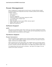
... the Last Power State feature in before power was interrupted (either on page 57 for the location of ACPI with the Desktop Board requires an operating system that provides full ACPI support. When resuming from Consumer IR Software Support ACPI ACPI gives the operating...-up support • Wake from an AC power failure, the computer returns to the power state it was in the BIOS Setup program's Boot menu. Intel Desktop Board DP55KG Product Guide Power Management Power management is implemented at several levels, including software support through system control. The computer's response ...
... the Last Power State feature in before power was interrupted (either on page 57 for the location of ACPI with the Desktop Board requires an operating system that provides full ACPI support. When resuming from Consumer IR Software Support ACPI ACPI gives the operating...-up support • Wake from an AC power failure, the computer returns to the power state it was in the BIOS Setup program's Boot menu. Intel Desktop Board DP55KG Product Guide Power Management Power management is implemented at several levels, including software support through system control. The computer's response ...
Product Guide
Page 28
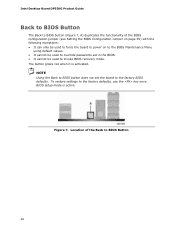
...Intel Desktop Board DP55KG Product Guide Back to BIOS Button The Back to BIOS button (Figure 7, A) duplicates the functionality of the Back to BIOS Button 28 To restore settings to the factory defaults, use the key once BIOS setup mode is activated. The button glows red when it is active. Location of the BIOS configuration jumper (see Setting the BIOS...only be used to force the board to power on to the BIOS Maintenance Menu using default values. • It cannot be used to the factory BIOS defaults. NOTE Using the Back to BIOS button does not set in the BIOS. • It cannot be ...
...Intel Desktop Board DP55KG Product Guide Back to BIOS Button The Back to BIOS button (Figure 7, A) duplicates the functionality of the Back to BIOS Button 28 To restore settings to the factory defaults, use the key once BIOS setup mode is activated. The button glows red when it is active. Location of the BIOS configuration jumper (see Setting the BIOS...only be used to force the board to power on to the BIOS Maintenance Menu using default values. • It cannot be used to the factory BIOS defaults. NOTE Using the Back to BIOS button does not set in the BIOS. • It cannot be ...
Product Guide
Page 31
.... Follow these guidelines before performing any procedures can damage components. 2 Installing and Replacing Desktop Board Components This chapter tells you how to: • Install the I/O shield • Install and remove the Desktop Board • Install and remove a processor • Install and remove memory •...the audio system • Connect chassis fan and power supply cables • Connect the Bluetooth Module antenna • Set the BIOS configuration jumper • Clear passwords • Replace the battery Before You Begin CAUTIONS The procedures in this chapter only at ...
.... Follow these guidelines before performing any procedures can damage components. 2 Installing and Replacing Desktop Board Components This chapter tells you how to: • Install the I/O shield • Install and remove the Desktop Board • Install and remove a processor • Install and remove memory •...the audio system • Connect chassis fan and power supply cables • Connect the Bluetooth Module antenna • Set the BIOS configuration jumper • Clear passwords • Replace the battery Before You Begin CAUTIONS The procedures in this chapter only at ...
Product Guide
Page 51
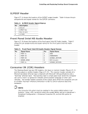
... be enabled in order to emulate "learned" infrared commands in the system BIOS before it can use to control external electronic hardware. Press at boot to enter the system BIOS, and go to Advanced > Peripheral Configuration > Enhanced Consumer IR, and ...6 SENSE1_RETURN 8 KEY (no pin) 4 +5 VDC Front Panel Intel HD Audio Header Figure 27, B shows the location of a filtered translated infrared input compliant with Microsoft CIR specifications and a "learning" infrared input. Installing and Replacing Desktop Board Components S/PDIF Header Figure 27, A shows the location of other...
... be enabled in order to emulate "learned" infrared commands in the system BIOS before it can use to control external electronic hardware. Press at boot to enter the system BIOS, and go to Advanced > Peripheral Configuration > Enhanced Consumer IR, and ...6 SENSE1_RETURN 8 KEY (no pin) 4 +5 VDC Front Panel Intel HD Audio Header Figure 27, B shows the location of a filtered translated infrared input compliant with Microsoft CIR specifications and a "learning" infrared input. Installing and Replacing Desktop Board Components S/PDIF Header Figure 27, A shows the location of other...
Product Guide
Page 59
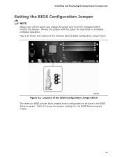
Figure 32. Table 13 shows the jumper settings for the BIOS Setup program modes. 59 Moving the jumper with the power on may result in the BIOS Setup program. Location of the Desktop Board's BIOS configuration jumper block. Figure 32 shows the location of the BIOS Configuration Jumper Block The three-pin BIOS jumper block enables board configuration to be done in unreliable computer operation. Installing and Replacing Desktop Board Components Setting the BIOS Configuration Jumper NOTE Always turn off the power and unplug the power cord from the computer before moving the jumper.
Figure 32. Table 13 shows the jumper settings for the BIOS Setup program modes. 59 Moving the jumper with the power on may result in the BIOS Setup program. Location of the Desktop Board's BIOS configuration jumper block. Figure 32 shows the location of the BIOS Configuration Jumper Block The three-pin BIOS jumper block enables board configuration to be done in unreliable computer operation. Installing and Replacing Desktop Board Components Setting the BIOS Configuration Jumper NOTE Always turn off the power and unplug the power cord from the computer before moving the jumper.
Product Guide
Page 60
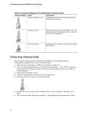
... displays the Maintenance menu. 60 Disconnect the computer's power cord from the AC power source (wall outlet or power adapter). 3. Intel Desktop Board DP55KG Product Guide Table 13. Place the jumper on page 31. 2. Recovery (None) The BIOS recovers data in the computer and the configuration jumper block is installed in the event of a failed...
... displays the Maintenance menu. 60 Disconnect the computer's power cord from the AC power source (wall outlet or power adapter). 3. Intel Desktop Board DP55KG Product Guide Table 13. Place the jumper on page 31. 2. Recovery (None) The BIOS recovers data in the computer and the configuration jumper block is installed in the event of a failed...
Product Guide
Page 61
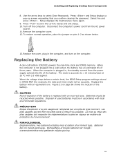
...ée est remplacée par une pile de type incorrect. To restore normal operation, place the jumper on pins 1-2 as shown below a certain level, the BIOS Setup program settings stored in , the standby current from the AC power source. 11. The clock is replaced with local environmental regulations. CAUTION Risk of... on page 66 shows the location of used batteries must be recycled where possible. Disposal of the battery. Select Yes and press . Installing and Replacing Desktop Board Components 8. Replace the cover, plug in accordance with an incorrect type.
...ée est remplacée par une pile de type incorrect. To restore normal operation, place the jumper on pins 1-2 as shown below a certain level, the BIOS Setup program settings stored in , the standby current from the AC power source. 11. The clock is replaced with local environmental regulations. CAUTION Risk of... on page 66 shows the location of used batteries must be recycled where possible. Disposal of the battery. Select Yes and press . Installing and Replacing Desktop Board Components 8. Replace the cover, plug in accordance with an incorrect type.
Product Guide
Page 67
... for multiple identical systems.) 4. Close all other applications. This step is required. This runs the update program. 6. 3 Updating the BIOS The BIOS Setup program can be rebooted at the last Express BIOS Update window. 5. Follow the instructions provided in the Windows environment. Navigate to the Intel World Wide Web site: http://support.intel.com/support/motherboards/desktop/ 2.
... for multiple identical systems.) 4. Close all other applications. This step is required. This runs the update program. 6. 3 Updating the BIOS The BIOS Setup program can be rebooted at the last Express BIOS Update window. 5. Follow the instructions provided in the Windows environment. Navigate to the Intel World Wide Web site: http://support.intel.com/support/motherboards/desktop/ 2.


